Viessmann Vitocell 100-E Installation And Service Instructions Manual
Hide thumbs
Also See for Vitocell 100-E:

Related Manuals for Viessmann Vitocell 100-E


Summary of Contents for Viessmann Vitocell 100-E
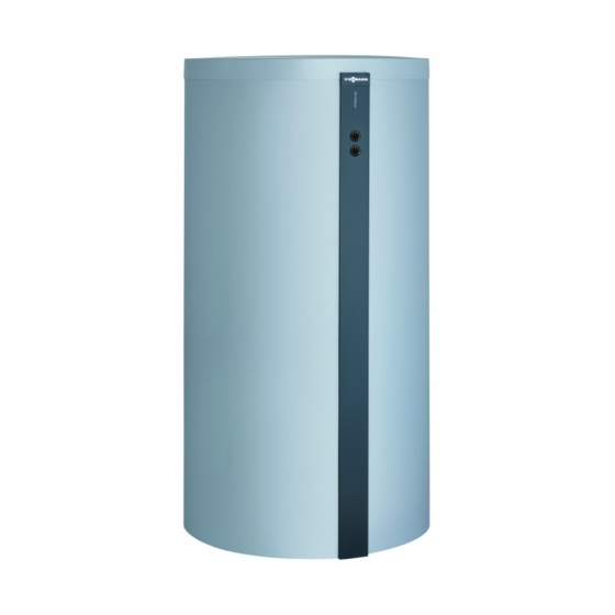
- Page 1 VIESMANN Installation and service instructions for contractors Vitocell 100-E Type SVPB Heating water buffer cylinder 600 to 950 l VITOCELL 100-E Please keep safe. 6154019 GB 4/2020...
-
Page 2: Safety Instructions
Safety instructions Safety instructions Please follow these safety instruc- tions closely to prevent accidents and material losses. Safety instructions explained Danger Note This symbol warns against the risk Details identified by the word "Note" of injury. contain additional information. Please note This symbol warns against the risk of material losses and environmen- tal pollution. -
Page 3: Repair Work
Please note Repairing components that fulfil a safety function can compromise the safe operation of the system. Replace faulty components only with genuine Viessmann spare parts. Auxiliary components, spare and wearing parts Please note Spare and wearing parts that have... - Page 4 Index Index Information Disposal of packaging ................Symbols ....................Intended use ..................Product information ................System examples .................. Spare parts lists ..................Preparing for installation Connections ................... Installation sequence Siting the cylinder .................. Fitting the lower thermal insulation mat and aligning the cylinder body Fitting the thermometer sensor (if supplied) and cylinder temperature sensor ....................
-
Page 5: Disposal Of Packaging
Information Disposal of packaging Please dispose of packaging waste in line with statu- tory regulations. Symbols Symbol Meaning Reference to other document containing further information Step in a diagram: The numbers correspond to the order in which the steps are carried out. Warning of material losses and environ- mental pollution Live electrical area... -
Page 6: Product Information
Incorrect usage also occurs if the components in the system are modified from their intended use (e.g. through direct DHW heating in the collector). Product information Vitocell 100-E, type SVPB (600, 750 and 950 l ■ Suitable for systems to EN 12 828 and DIN 4753. capacity) ■... -
Page 7: Preparing For Installation
Preparing for installation Connections Back Front Thermometer sensor fixing (underneath the thermal Heating water flow 1 (to the heating circuits)/air insulation) vent valve Thermometer, up to 4 pce (accessories) Heating water flow 2 (from the heat generator) Heating water flow G 1 Clamping system for cylinder temperature sensor Return stratification G 1 (behind the thermal insulation) - Page 8 Installation sequence Siting the cylinder Please note Please note Exposure to frost can damage the appliance. The thermal insulation must not come into con- Install the buffer cylinder in a room that is free tact with naked flames. from the risk of frost and draughts. Otherwise, Exercise caution when welding and brazing.
- Page 9 Installation sequence Fitting the lower thermal insulation mat and… (cont.) Note Only use one or two of the adjustable feet to level the cylinder body. At least one of the adjustable feet must remain fully screwed in. ≤35 Fig. 2 Do not extend the adjustable feet beyond a total length of 35 mm.
- Page 10 Installation sequence Fitting the thermometer sensor (if supplied) … (cont.) 2. Guide the upper thermometer sensor through the 6. Tighten the nuts. lifting eye, insert it into the clamping bracket as far as it will go and tighten the wing nut. 7.
- Page 11 Installation sequence Mounting the Vitotrans (cont.) Fig. 5 1. Fit the bolts to the cylinder body. 3. Turn the nuts onto the bolts by hand. 2. Mount the module. DE F Fig. 6 1. Connect heating water flow connection pipe 3.
- Page 12 Installation sequence Fitting the thermal insulation jacket Note Fleece remnants must not enter the heating water buf- fer cylinder through the cylinder connections. Fig. 7 Note 2. Fit 4 clip fasteners above and 2 clip fasteners 2 people are required for the following work. behind the Vitotrans so that they are evenly spaced.
-
Page 13: Fitting The Cover Strips
Installation sequence Fitting the cover strips Fig. 8 1. Tighten the nuts on the bolts. 3. Insert the rear sections of the Vitotrans thermal insulation. When doing this, observe the groove in 2. Fit the cover strip. the thermal insulation. Version with Vitotrans: Separate the cover strip at slot and fit the upper... - Page 14 Installation sequence Fitting the cover strips (cont.) Fig. 9 Illustration shows: Vitocell 100-E, type SVPB, 600 l Type plate 1. Version with Vitotrans: 3. Fit the rear cover strip to the thermal insulation. mount the front section of the Vitotrans thermal insulation.
-
Page 15: Fitting The Cover
Installation sequence Fitting the cover Fig. 10 Viessmann logo Making the connections on the heating water side Any number of heating water buffer cylinders, type Note SVPB, can be connected in series or in parallel. Pro- For location of connections, see page 7. -
Page 16: Connecting The Equipotential Bonding
Installation sequence Making the connections on the heating water side (cont.) Cylinder bank connected in series Fig. 11 Heating water return 3 (from the heating circuits) Heating water flow 2 (from the heat generator) Heating water return 4 (to the heat generator) Air vent valve Heating water flow 1 (to the heating circuits) Drain... -
Page 17: Commissioning/Service Reports
Commissioning/service reports Commissioning/service reports Commissioning Maintenance/service Maintenance/service Date: Maintenance/service Maintenance/service Maintenance/service Date: Maintenance/service Maintenance/service Maintenance/service Date: Maintenance/service Maintenance/service Maintenance/service Date: Maintenance/service Maintenance/service Maintenance/service Date:... - Page 18 Specification Specification Cylinder capacity Standby heat loss kWh/24 h 2.10 2.25 2.45 to EN 12897 with 45 K temperature differential Dimensions Length ( Incl. thermal insulation 1064 1064 1064 ■ Excl. thermal insulation ■ Width 1119 1119 1119 Height Incl. thermal insulation 1645 1900 2200...
-
Page 19: Final Decommissioning And Disposal
Disposal Final decommissioning and disposal Viessmann products can be recycled. Components For decommissioning the system, isolate the system and substances from the system are not part of ordi- from the power supply and allow components to cool nary household waste. - Page 20 Certificates Declaration of conformity We, Viessmann Werke GmbH & Co. KG, D-35107 Allendorf, declare as sole responsible body that the named product complies with the European directives and supplementary national requirements in terms of its design and operational characteristics. Using the serial number, the full Declaration of Con- formity can be found on the following website: www.viessmann.co.uk/eu-conformity...
- Page 21 Keyword index Keyword index Adjustable feet............. 8 Permissible operating pressure........15 Permissible temperature..........15 Product information............6 Connections..............7 Connections, heating water side........ 15 Cylinder, siting..............8 Specification...............18 Cylinder bank............. 16 Cylinder temperature sensor........9, 10 Temperature, permissible...........15 Test pressure..............15 Heating water side connections......... 15 Thermometer sensor............9 Intended use..............
- Page 24 Viessmann Werke GmbH & Co. KG Viessmann Limited D-35107 Allendorf Hortonwood 30, Telford Telephone: +49 6452 70-0 Shropshire, TF1 7YP, GB Fax: +49 6452 70-2780 Telephone: +44 1952 675000 www.viessmann.com Fax: +44 1952 675040 E-mail: info-uk@viessmann.com...