Table of Contents
Advertisement
Advertisement
Table of Contents

Related Manuals for Garmin GTN 650Xi Series


Summary of Contents for Garmin GTN 650Xi Series
- Page 1 GTN Xi Series Pilot's Guide...
- Page 2 Garmin. ® The Bluetooth word mark and logos are registered trademarks owned by Bluetooth SIG, Inc. and any use of such marks by Garmin is under license. Other trademarks and trade names are those of their respective owners. ® Iridium is a registered trademark of Iridium Communications, Inc.
-
Page 3: Table Of Contents
Table of Contents 1 SYSTEM AT A GLANCE ..................... 1-1 Overview ..............................1-2 Unit Configurations ..................1-3 Apps & Features ..................... 1-4 Pilot Interface ............................1-5 Bezel ......................1-5 SD Card Slot ....................1-7 Touchscreen ....................1-8 Gestures ....................1-8 Keys ......................1-9 Menus ..................... - Page 4 Table of Contents Adjust Sidetone Volume Offset ..............2-29 Tuning & Monitoring ................... 2-30 Direct Tuning ................... 2-31 Transfer Frequency to Active (Flip-Flop) ............. 2-34 Remote Radio Control ................2-35 Monitor Mode ..................2-37 Frequency Selection ..................2-38 Search Tabs ....................2-38 Remote Frequency Selection ..............
- Page 5 GPS Status Annunciations ................ 2-90 GPS Alerts ....................2-91 LRU Status ....................2-92 Logs ................................2-93 Export to an SD Card ................2-95 Streaming to Garmin Pilot ................ 2-97 3 NAVIGATION ......................... 3-1 Map ................................3-4 Map Setup ..................... 3-8 Map Display Orientation ................3-9 North Up Above ..................
- Page 6 Table of Contents Visual Approach ..................3-10 Auto Zoom ....................3-11 Track Vector ..................... 3-12 Altitude Constraints ................. 3-12 Glide Range Ring ..................3-13 NAV Range Ring ..................3-17 Fuel Range Ring ..................3-17 TOPO Scale ....................3-18 Chart Color Scheme ................. 3-18 Selected Altitude Range Arc ..............
- Page 7 Table of Contents Define a VNAV Profile ................3-80 Altitude Constraints ................. 3-81 VNAV Direct To ..................3-85 Transition to Approach ................3-85 Temperature Compensated Altitude ............3-86 OBS ......................3-87 Dead Reckoning ................... 3-88 Parallel Track ....................3-89 Invert Flight Plan ..................3-91 Edit Data Fields ....................
- Page 8 Table of Contents DME Arc ....................3-133 RF Legs ....................3-134 Vectors to Final ..................3-134 ILS Approach ..................3-135 RNAV Approaches .................. 3-135 Visual Approach ..................3-142 Autopilot Outputs .................. 3-144 4 PLANNING ..........................4-1 VCALC .................................4-4 Define a VCALC Profile .................. 4-4 VCALC Setup ....................
- Page 9 Table of Contents METARs and TAFs ..................5-28 PIREPs ...................... 5-29 SIGMETs ....................5-30 Surface Analysis ..................5-30 TFRs ....................... 5-31 Turbulence ....................5-32 Winds Aloft ....................5-33 SiriusXM Weather ..................5-35 Activate SiriusXM Services ................ 5-35 SiriusXM Weather Setup ................5-37 FIS-B Weather ....................
- Page 10 Table of Contents Terrain Configurations ................. 5-97 GPS Altitude for Terrain ................5-98 Database Limitations ..................5-99 Terrain Display ................... 5-100 Terrain Setup ..................... 5-101 Terrain Proximity ..................5-103 Terrain Elevation Depictions ..............5-103 Obstacle Elevation Depictions ..............5-104 Alert Types ..................... 5-106 Alerting Thresholds ................
- Page 11 Table of Contents Counters & Timers ..................7-21 Position Reporting ..................7-21 Contacts ...................... 7-22 Create a Contact ..................7-22 Find a Contact ..................7-23 Contact Options ..................7-23 8 MESSAGES ..........................8-1 Advisory Messages ..........................8-2 Message Key ....................8-3 Airspace Advisories ..................
- Page 12 INTENTIONALLY LEFT BLANK Pilot’s Guide 190-02327-03 Rev. C...
- Page 13 Warnings, Cautions & Notes WARNING Do not use terrain avoidance displays as the sole source of information for maintaining separation from terrain and obstacles. Garmin obtains terrain and obstacle data from third-party sources and cannot independently verify the accuracy of the information.
- Page 14 Warnings, Cautions & Notes WARNING Never use basemap information (land and water data) as the sole means of navigation. Basemap data is intended only to supplement other approved navigation data sources and should be considered only an aid to enhance situational awareness.
- Page 15 State of California to cause cancer, birth defects, or reproductive harm. This notice is being provided in accordance with California’s Proposition 65. If you have any questions or would like additional information, please refer to our website at www.garmin.com/prop65. 190-02327-03 Rev. C Pilot’s Guide...
- Page 16 They will harm the anti-reflective coating. Use a clean, lint-free cloth and anti-reflective lens cleaner. CAUTION Ensure that any unit repairs are made by an authorized Garmin service center. Unauthorized repairs or modifications could void both the warranty and affect the airworthiness of the aircraft.
- Page 17 Warnings, Cautions & Notes NOTE This device complies with part 15 of the FCC Rules. Operation is subject to the following two conditions: (1) this device may not cause harmful interference, and (2) this device must accept any interference received, including interference that may cause undesired operation.
- Page 18 “Aviation Database Declarations.” • Use of a current Garmin or Jeppesen database in your Garmin equipment is required for compliance with established FAA regulatory guidance, but does not constitute authorization to fly any and all terminal procedures that may be presented by the system.
- Page 19 Warnings, Cautions & Notes NOTE Information obtained solely through FIS-B does not replace a thorough preflight briefing. NOTAMs received via FIS-B uplink may not be a complete listing. Active NOTAMs are removed from the FIS-B data stream 30 days after issuance. FIS-B uplink is not an FAA approved source for NOTAMs.
- Page 20 Available for Download Electronic Pilot’s Guide A version of this guide saved in Adobe Acrobat. Available for viewing on your computer or portable device. Upgrade Supplement Details document changes for software enhancements. Go to garmin.com/manuals xviii Pilot’s Guide 190-02327-03 Rev. C...
- Page 21 About This Guide Layout The design and layout of this guide is SECTION TITLE intended to provide clear, concise System at a Glance sections written in the logical order of a pilot’s flight instrument and Get Started systems scan. Navigation Planning Hazard Awareness Abnormal Operations...
- Page 22 About This Guide Product Descriptions This guide covers the operation of the following Garmin product series. GTN 650Xi Series GTN 750Xi Series When you see It means a product name in bold the information pertains to that (e.g., GTN 750Xi)
- Page 23 About This Guide Special Notations This guide uses the following message types when applicable. WARNING Indicates when serious injury or death will occur. CAUTION Indicates when equipment damage is possible. NOTE Emphasizes a point about a specific feature, function, or operation. Insets These boxes may include a list of features or application functions, references to additional information, or a useful pilot’s tip.
- Page 24 G500(H)/G600/G700 TXi Pilot’s Guide 190-01717-10 GTX 335/345 All-In-One ADS-B Transponder Pilot’s Guide 190-01499-00 Telligence Voice Command Guide 190-01007-50 Reference Websites WEBSITE ADDRESS Aviation Limited Warranty https://www.garmin.com/en-US/legal/aviation-limited-warranty Go to http://www.flygarmin.com/support and select Database Concierge Database Management. ADS-B Academy https://www.garmin.com/us/intheair/ads-b Connext http://www.garmin.com/connext FAA Regulatory and https://rgl.faa.gov...
-
Page 25: System At A Glance
1 System at a Glance OVERVIEW.........................1-2 PILOT INTERFACE ....................1-5 COMPATIBLE EQUIPMENT................1-20... -
Page 26: Overview
System at a Glance Overview Two series of panel mount navigators comprise the GTN Xi Series. The primary difference between these displays is the size of the screen. 4.9” GTN 650Xi Series 6.9” GTN 750Xi Series GTN 625Xi GTN 725Xi... -
Page 27: Unit Configurations
System at a Glance Unit Configurations GTN 625Xi GTN 635Xi GPS/MFD GPS/MFD/COM GTN 650Xi GPS/MFD/COM/NAV GTN 725Xi GTN 750Xi GPS/MFD GPS/MFD/COM/NAV COMPARISON TABLE Remote Chart Weather Audio GTN Xi GPS/MFD Radio Radio Display Radar Panel • • • • • •... -
Page 28: Apps & Features
System at a Glance Apps & Features COMMON FEATURES While features vary depending on model and unit configuration, all Airways models share many of the same Arrivals features. Approaches Checklists Database Concierge Access Datalink Weather Departures Flight Plan Graphical Flight Planning Iridium Phone/SMS Moving Map Waypoints (includes user-generated... -
Page 29: Pilot Interface
Pilot Interface Bezel The bezel provides a combination of mechanical knobs and push-keys. Active touch areas on the display screen allow access to unit features and apps. GTN 750Xi Series Touchscreen GTN 650Xi Series Touchscreen 190-02327-03 Rev. C Pilot’s Guide... - Page 30 Home Key Shortcuts GTN 650Xi Series: Pushing and holding the Home key provides direct access to Default Navigation features. GTN 750Xi Series: Pushing and holding the Home key provides direct access to the moving map.
-
Page 31: Sd Card Slot
System at a Glance SD Card Slot NOTE Do not remove or insert an SD card while in flight. Always verify the system is powered off before inserting or removing an SD card. FEATURE LIMITATIONS • SD card in the FAT32 format, with memory capacity between 8 GB and 32 GB The navigator requires an SD card for the following tasks. -
Page 32: Touchscreen
System at a Glance Touchscreen A multi-touch color display provides onscreen controls for unit operation. Gestures Touching the screen briefly with a single finger. Use this gesture for: • Opening a page or menu • Activating a command key or data entry field •... -
Page 33: Keys
System at a Glance Keys COMMON COMMANDS Open the system messages list. Open a context menu. A flashing icon indicates unread messages. Cancel an active function without Return to the previous page. inputting data. Select the corresponding item Confirm the requested action (e.g., database update). - Page 34 System at a Glance FUNCTION KEYS Toggle keys turn a specific function on or off. The current state of the function is indicated below the key label. APP ICONS Tapping one of these icons opens the corresponding application. Some apps provide additional icons for accessing functions on subpages (e.g., System, Utilities).
-
Page 35: Menus
System at a Glance Menus Menus group related controls into an expandable pane, allowing access to multiple functions on a single page. Depending on the number of available functions, a menu may comprise more than one pane. POP-UP MENUS Pop-up menus open to the default or previously selected value. -
Page 36: Tabs
System at a Glance Tabs Tabs group information into individual panes. Content includes scrolling lists, data fields, function keys, or a combination of controls. Tabs are located along the left and right sides of a pane. Active Inactive Tabs Inactive Tabs Keyboards The navigator employs multiple keyboard types to serve specific settings and... - Page 37 An indicator shows which keyset is active. Keys A through M are active by default. Active Keyset For convenience, GTN 650Xi Series navigators provide a slider, allowing you to quickly select a group of five keys at any given time. Slider, GTN 650Xi Series...
-
Page 38: Control Knobs
System at a Glance Control Knobs Outer Inner Dual Concentric Knob Volume/Squelch Knob Inner and outer control knobs offer A single volume knob controls an alternative method for selecting audio volume for the selected and modifying data without the COM radio, NAV receiver, and/or use of touch keys. -
Page 39: Page Navigation Labels
Default Navigation features Slot 9, the last slot, opens the Nearest Airport menu. For more about customizable page GTN 750Xi Series only. slots, read Page Shortcuts in section 2. GTN 650Xi Series only. 190-02327-03 Rev. C Pilot’s Guide 1-15... -
Page 40: Knob Function Indicators
Home Page Active Available functions: • Multiple pane scrolling (GTN 650Xi Series only) • Set knob focus to COM standby frequency Dual Concentric Knob Shortcuts GTN 650Xi/750Xi For convenience, a three-way toggle function allows you to access radio controls quickly via knob push. - Page 41 System at a Glance When GTN is not in page navigation mode, the available dual concentric knob functions annunciate at the bottom of the display. Numeric Keypad Active COM Standby Frequency Active Available functions: Available functions: • • Set knob focus to NAV Numeric data entry standby frequency •...
- Page 42 System at a Glance Screen Captures FEATURE REQUIREMENTS • SD card in the FAT32 format, with memory capacity between 8 GB and 32 GB Save images to an SD card at any time using a screen capture. 1. Verify unit power is off and the card slot is empty. 2.
-
Page 43: Color Conventions
System at a Glance Color Conventions • Warning conditions Yellow • Cautionary conditions Green • Safe operating conditions • Engaged modes • Active COM frequency White • Scales and markings • Current data and values Magenta • GPS data • Active flight plan legs Cyan •... -
Page 44: Compatible Equipment
Autopilot replacement. Optional LRUs may include Flight Stream 210/510 compatible equipment from either Garmin or a third party manufacturer. G3X Touch These vary by unit and installation type (VFR or IFR). G500/G600 Some LRUs provide features that... -
Page 45: Get Started
2 Get Started POWER UP ........................2-2 DATABASES.......................2-5 CONNECTIVITY....................2-19 COM........................... 2-23 NAV ..........................2-43 AUDIO PANEL....................... 2-46 XPDR ......................... 2-56 ADS-B ALTITUDE REPORTING..............2-62 PILOT SETTINGS....................2-65 STATUS INDICATIONS ..................2-82 LOGS.......................... 2-93... -
Page 46: Power Up
Get Started Power Up The unit receives power directly from the aircraft’s electrical system. Upon power-up, the bezel key backlight momentarily illuminates. System failure annunciations typically disappear within the first 30 seconds after power-up. The start-up screen presents the unit software versions, the name and status of all installed databases, and the Database Updates page access key. -
Page 47: Instrument Panel Self-Test
Tapping Continue advances to the Home page. If an instrument remains flagged after one minute, check the status of the associated LRU, then contact a Garmin dealer for support. Preset Fuel Quantities CAUTION Ensure that estimated fuel quantity values are accurate before flight. - Page 48 Get Started FUEL CAPACITY ENTRY KEYS Set Full/Tabs Opens the Fuel Capacity Setup menu. Select the appropriate data entry key and enter the estimated fuel amounts. Fuel Full Capacity: Specify the tank full amount. Fuel Tab Capacity: Specify the tank tab amount. These values vary according to aircraft type.
-
Page 49: Databases
Load databases via SD card. Once loading completes, you may power off the unit and remove the card. • Transfer databases from a Flight Stream 510 wireless datacard. This method requires the Garmin Pilot app on a portable electronic device. SUPPORTED DATABASES Bodies of water, geopolitical boundary, and road Basemap... -
Page 50: Database Effective Cycles
Get Started Database Effective Cycles Most databases expire at regular intervals. Exceptions include Basemap and Terrain, which neither expire nor update on a regular schedule. The start-up page lists all currently installed databases. Review this list for current database types, cycle numbers, and expiration dates. -
Page 51: Active And Standby Databases
Get Started Active and Standby Databases The navigator uses two types of databases: Active Databases Standby Databases The databases in use by the system. Databases that have not reached the effective date. These remain on the SD card until they become effective. Database Info WHERE TO FIND IT During normal operation, you can view... - Page 52 Get Started STANDBY DATABASE LIST Selecting Standby displays information about databases that are not yet effective. GTN Xi notifies when no standby databases are available. DATABASE NOT FOUND Notifications for databases not present or available also display in the form of system messages. Review the Active Database Info list to determine the status of the indicated database.
-
Page 53: Manual Updates
DATABASE SOURCE INDICATION Connext Icon A Connext icon indicates when a database is from Garmin Pilot via wireless transfer. No indication means the database is either from an SD card or the unit’s internal standby queue. - Page 54 Get Started SELECT ALL DATABASES Select individual databases for transfer, or choose Select All if all listed databases require updating. By default, this page displays only the databases recommended for update. A message notifies when no such databases are available. After all selections are made, initiate the update process by tapping Start.
- Page 55 Get Started SHOW ALL DATABASES Tapping Show All displays a complete list of all databases. This list may include databases that are: • Not yet effective • Older than the currently active database(s) • Unable to update due to an error ERROR INFORMATION To determine the cause of a database error, tap Error Info.
- Page 56 Get Started SELECT REGION This key appears when two databases are of the same type and cycle, but pertain to different regions. To specify a database region: Tap Select Region, then select the appropriate menu option. 2-12 Pilot’s Guide 190-02327-03 Rev. C...
-
Page 57: Automatic Updates
Get Started Automatic Updates When a newer database is available, Automatic updates occur follow the on-screen prompts to when: complete the update process. • A newer database is detected on the SD card or in the internal standby queue • A newer database is within its effective dates •... - Page 58 Get Started Select the databases for transfer, then tap Start. All newer databases (effective and expired) transfer from the SD card to the internal standby queue. A progress bar displays the name of each database as it uploads to the unit. Terrain databases may require up to 5 minutes for transfer.
-
Page 59: Database Concierge
Database Concierge allows wireless transfer of databases from a mobile device while the aircraft is on ground. A pilot selects and downloads databases inside the Garmin Pilot app. Transfers occur once Flight Stream 510 establishes a wireless connection inside the aircraft. Database Concierge Transfer Function •... - Page 60 Get Started Database Concierge transfers databases from the app to Flight Stream 510. A progress bar shows when this process is complete. GTN Xi either updates or preloads databases based on their effective date. A second progress bar indicates upload status.
-
Page 61: Database Sync
Chart Streaming function (if enabled). Database SYNC Transfer Function • Enables automatic database synchronization across all capable Garmin avionics • Includes active and standby databases • Prompts unit restart if a new database is effective and the aircraft is ground 190-02327-03 Rev. -
Page 62: Chart Streaming
Get Started Chart Streaming Chart Streaming allows streaming of individual charts on an as-needed basis until database sync is complete. Toggling this function off has no affect on Database SYNC. FEATURE LIMITATIONS • Available only when Database Sync is active and a current chart database is available WHERE TO FIND IT This function resides in the System Status menu. -
Page 63: Connectivity
• Auto reconnect function is not available for Android devices Connext Setup The Connext interface allows communication Home Home with Garmin Pilot from a portable electronic device. System System Connext Setup Connext Setup Connext Features The following features are available on your portable electronic device. -
Page 64: Bluetooth Setup
Get Started Bluetooth Setup The unit supports wireless pairing with Bluetooth Wireless up to 13 portable electronic devices via Features the Garmin Pilot app. • FIS-B weather Bluetooth device management options • reside on the Paired Devices page. ADS-B traffic Opening this page automatically •... -
Page 65: Managing Paired Devices
Get Started Managing Paired Devices To view a list of all paired devices and their connection status, tap Manage Paired Devices. To enable automatic connection between the unit and a paired device at power up, tap Auto Reconnect. AUTO RECONNECT Enables automatic connection between the unit and the paired device when the two are within range. -
Page 66: Wi-Fi Setup
Flight Stream 510 requires power up. Wi-Fi is active, but the unit is waiting to connect with a device. Connection complete. Flight Stream 510 requires Garmin Pilot to be opened in order for database transfer to commence. Garmin Pilot opened and streaming to unit. -
Page 67: Com
Get Started AVAILABLE WITH: GTN 635Xi/650Xi/750Xi COM Standby Control Panel VHF COM transceiver controls are accessible via the selectable standby (STBY) frequency window. Frequency Entry Field Transfer (Flip-Flop) Key Find Key Data Entry Keys Monitor Key From the COM Standby control panel you can: •... -
Page 68: Com Volume Controls
Get Started COM Volume Controls Percent of Relative Volume Adjust radio volume with the small Max Volume Indicator knob according to your preference. The unit retains volume settings over power cycles. Open Squelch Push the volume/squelch knob to override the automatic squelch function. -
Page 69: Com Radio Setup
Get Started COM Radio Setup WHERE TO FIND IT COM radio customization options are accessible via the System Setup app. System System Setup COM/NAV COM Channel Spacing Key Knob Control Radios Key Knob Control Default Key COM Sidetone Controls Reverse Frequency Lookup Key From here you can: •... -
Page 70: Set Com Channel Spacing
Get Started Set COM Channel Spacing The unit supports channel tuning for both 8.33 kHz and 25 kHz channels within radio-frequency range. Channel spacing is set to 25.0 kHz by default. Tapping COM Channel Spacing toggles the transceiver channel spacing between 8.33 kHz and 25.0 kHz. -
Page 71: Revert Knob Function To Radio Control
Get Started Revert Knob Function to Radio Control You may change the default function of the dual concentric knob to accommodate your workflow. Knob control is set to Page Navigation by default. Tapping Knob Control Default changes the default setting to COM Radio for standby frequency control. Page navigation remains accessible via knob push. -
Page 72: Enable Reverse Frequency Look-Up
Get Started Enable Reverse Frequency Look-up FEATURE REQUIREMENTS • Valid position data • Active navigation database FEATURE LIMITATIONS • Available only for the nearest stations in the database Enabling this option displays the facility identifier and frequency type for active and standby frequencies. The unit verifies the displayed frequency against the database at least once per minute. -
Page 73: Adjust Sidetone Volume Offset
Get Started Adjust Sidetone Volume Offset FEATURE LIMITATIONS • Availability dependent upon configuration • Offset range: +/-25% of total COM audio volume range Numeric If the unit is wired for audio Offset Value output, set the sidetone volume offset to the preferred level. By default, the offset value is set to zero percent. -
Page 74: Tuning & Monitoring
Get Started Tuning & Monitoring Communication frequencies are split between two selectable windows. Active The upper window presents the active Frequency COM radio frequency. This is the frequency currently in use for transmit Standby and receive operations. Frequency The lower window presents the standby radio frequency. -
Page 75: Direct Tuning
Get Started Direct Tuning You may enter a standby frequency using the data entry keys on the COM Standby control panel or by turning the control knob. Tapping STBY opens the control panel. From here you may specify a frequency or select one using the provided search options. - Page 76 Get Started FREQUENCY AUTOFILL Numeric characters autofill the first valid frequency value based on each selected digit. Autofill characters are muted and display from the cursor position to the right of the field. Matching Frequency Selecting a digit that is not valid for the cursor location results in no entry.
- Page 77 Get Started KNOB TUNING The dual concentric control knob allows you to enter a standby frequency without opening the control panel. Pushing the knob toggles between radio and page navigation functions. The selected STBY If no action occurs, When the STBY COM frequency is no longer window turns cyan the selected STBY...
-
Page 78: Transfer Frequency To Active (Flip-Flop)
Get Started Transfer Frequency to Active (Flip-Flop) Before After The transfer (or flip-flop) function allows you to swap the active and standby frequency values. This function is accessible multiple ways. ACTIVE FREQUENCY WINDOW Tapping this window swaps the active frequency value with the standby frequency displayed in the lower window. -
Page 79: Remote Radio Control
Get Started Remote Radio Control FEATURE REQUIREMENTS • Second GTN Xi series navigator: GTN 635Xi, GTN 650Xi, or GTN 750Xi FEATURE LIMITATIONS • Dual GTN Xi installations only • NAV radio options available only on GTN 650Xi/750Xi Some dual GTN Xi installations allow you to tune radio frequencies on both units from a single navigator. - Page 80 Get Started Radios are listed according to navigator (local/remote). Cyan denotes the current radio selection. A frequency control key allows you to open the standby control panel for the associated radio. Tapping Back closes the list and returns to the previous view. Selected Radio Indication Local...
-
Page 81: Monitor Mode
Get Started LOAD FREQUENCY OPTIONS You can load active or standby frequency values to any radio from a search tab or waypoint information page (i.e., Airport, VOR). Selecting a frequency from one of these locations opens a pop-up. Select the Active or Standby key for the appropriate radio. -
Page 82: Frequency Selection
Get Started Frequency Selection The unit provides multiple options for finding and selecting a standby frequency from the available database frequencies. Search Tabs The Find key provides access to multiple search tabs. Each tab displays a list of selectable identifiers based on specific criteria. Nearest Lists up to 25 airports within a 200 nm radius Airports... -
Page 83: Remote Frequency Selection
Get Started Remote Frequency Selection FEATURE LIMITATIONS • Availability dependent upon configuration On units configured for remote frequency recall, user frequencies are selectable via a remote switch. • Pressing the switch once loads the next user frequency into the STBY window •... -
Page 84: Create User Frequencies
Get Started Create User Frequencies FEATURE LIMITATIONS • Names may be up to seven characters in length • Maximum number of 15 user frequencies Create or edit user frequencies from the Edit Frequency Edit Frequency pop-up menu. Name Type name Frequency Specify Frequency Save Delete Name... - Page 85 Get Started ADD A USER FREQUENCY From the COM Standby page: 1. Tap Find > Select the User tab. 2. Tap Add User Frequency. 3. Specify the frequency name and value. 4. Tap Enter. A pop-up message informs when the user frequency list is full. EDIT USER FREQUENCY Tapping the Edit key for an existing entry opens the same pop-up.
-
Page 86: Com Alert
Get Started COM Alert If the radio fails: • Red “X” displays over the COM radio control • Advisory message alerts • COM control page is not available COM radio fail annunciations are designed to be immediately recognizable. If a failure occurs while the control page is active, the display automatically returns to the previous page. -
Page 87: Nav
Frequency lookup results are based on Frequency Identifier GPS position and database information. Based on GPS Position GTN 650Xi SERIES Due to spatial considerations, only one frequency control may display at a time. COM is the default frequency control option. 190-02327-03 Rev. C Pilot’s Guide... -
Page 88: Frequency Selection
Get Started STANDBY NAV FREQUENCY ENTRY Active NAV To change the standby frequency: Frequency 1. Push the dual concentric control knob repeatedly until the standby NAV frequency window is activated. 2. Rotate the inner and outer knobs or tap STBY and enter the frequency using the data entry keys. -
Page 89: Ident
Get Started IDENT IDENT Active When the standby NAV frequency window is Indication active, pushing the volume knob activates the NAV IDENT function. • “ID” annunciates in the active NAV frequency window • Morse code tones are audible Volume Knob Adjustments Turning the volume knob while the NAV frequency window is activated adjusts the radio’s volume percentage. -
Page 90: Audio Panel
Get Started Audio Panel AVAILABLE WITH: GTN 725Xi/750Xi Audio Panel Controls Audio panel controls are accessible via the Audio Panel key. This key is unavailable if the unit is not configured for audio or intercom LRUs, such as GMA 35. 2-46 Pilot’s Guide 190-02327-03 Rev. - Page 91 Get Started PLAYBACK CONTROLS The voice recorder feature records all audio heard on any MIC selected COM radio selected for transmission. Playback is heard by anyone listening on the selected radios. The clearance recorder can record up to 2.5 minutes of COM audio. Tap Playback Controls to: •...
-
Page 92: Mic Setup
Get Started Mic Setup MIC selection can be set in the MIC window or on the Audio Panel page. Tap MIC to toggle between MIC 1 and MIC 2. Under MIC Selection, select which COM you want as your MIC selection. The selected MIC is automatically monitored as indicated by the green numbers in the MON field. -
Page 93: Marker Audio
Get Started MARKER Audio The GMA 35 marker beacon receiver uses an audio indicator to alert you when the aircraft passes over a marker beacon transmitter. When a green bar displays on the MRKR Audio key, the audio from the receiver can be heard on the headsets. Tap MRKR Volume to set the volume level of the alert. -
Page 94: Intercom
Get Started Intercom AVAILABLE WITH: GTN 725Xi/750Xi Intercom Modes Intercom controls are accessible via the Intercom key. There are different modes of operation to control communication, music, and the telephone in the aircraft. Tap the arrow between the intercom recipients. When the arrow is green, it indicates communication is active between the recipients. -
Page 95: Intercom Setup
Get Started Intercom Setup Setup controls allow you to access: • Communication modes between pilot, co-pilot, and passenger • Distribution and mute options for two music interfaces • Distribution and volume of phone calls Passengers cannot transmit over the active COM radio, even if equipped with a PTT key. -
Page 96: Telephone Setup
Get Started Telephone Setup NOTE Garmin recommends when using the GSR 56 Iridium phone system that the audio only be activated when on a phone call. The GMA 35 provides a 2-way telephone interface and depends on the state of the telephone distribution. -
Page 97: Telligence Voice Command
FEATURE REQUIREMENTS • Compatible audio panel Garmin's Telligence Voice Command voice recognition feature allows the pilot and co-pilot to control the GTN Xi connected to a required GMA 35/350 using spoken commands. To activate Voice Recognition, push and hold the Push-to-Command (PTC) switch and speak a command. -
Page 98: Voice Command Setup
Get Started Voice Command Setup To enable voice recognition, tap System > Voice Commands > Voice Commands. VOICE COMMAND HISTORY Tap Command History to view a list of recently spoken commands. For a list of available voice recognition commands, consult Telligence Voice Command Guide. -
Page 99: Audio Panel Alert
Get Started Audio Panel Alert If the audio panel fails: • Red “X” displays over all audio panel-related controls • Advisory message alerts • Audio panel, intercom, and Telligence Voice Command functions are not available Audio panel fail annunciations are designed to be immediately recognizable. If a failure occurs while a control page is active, the display automatically returns to the previous view. -
Page 100: Xpdr
Get Started XPDR XPDR Control Panel Transponder controls are accessible via the XPDR key. This key is unavailable when the control panel is active. Squawk Code Entry Field XPDR Mode Selection Keys Squawk Code Entry Keys VFR Key The XPDR key becomes available when you: •... -
Page 101: Xpdr Setup
Get Started XPDR Setup Tap Menu to access the transponder setup XPDR Menu options. From here you can: Data Field • Change the display of data PRESS ALT • Enable 1090 ES ADS-B Out FLT ID functionality (if configured) ADS‐B Out • Assign a unique flight ID Flight ID Specify flight ID (if configurable) -
Page 102: Xpdr Modes
Get Started XPDR Modes Tapping Mode opens a menu of the available transponder modes. Options include Standby, On, and Altitude Reporting. MODE OPTIONS • Transponder does not reply to interrogations or transmit ADS-B Out Standby • Bluetooth wireless functions remain operational •... -
Page 103: Squawk Code Keys
Get Started Squawk Code Keys SPECIAL SQUAWK CODES Eight squawk code entry keys (0 – 7) provide access to all ATCRBS codes. 1200 Default VFR code (USA) Tapping one of these keys begins the 7500 Hijacking code selection sequence. 7600 Loss of communications Use the Backspace key or outer control knob to move the cursor. - Page 104 Get Started TRANSPONDER STATUS INDICATIONS IDENT Standby Mode • • Reply active Standby mode • • IDENT function active Current squawk code (inactive) • No change to transponder code IDENT with New Squawk Code Altitude Reporting Mode • • Reply active Altitude reporting mode •...
-
Page 105: Xpdr Alert
Get Started XPDR Alert If the transponder fails: • Red “X” displays over the IDENT key • Advisory message alerts • XPDR control page is not available Transponder fail annunciations are designed to be immediately recognizable. If a failure occurs while the control page is active, the display automatically returns to the previous view. -
Page 106: Ads-B Altitude Reporting
Get Started ADS-B Altitude Reporting FEATURE REQUIREMENTS • GDL 88 FEATURE LIMITATIONS • Display and control functionality dependent on GDL 88 configuration ADS-B Control Panel ADS-B Out controls are accessible via the ADS-B key. The location of this key varies by unit type. When interfaced to a GDL 88 GDL 88 Features transceiver, GTN Xi allows control over... -
Page 107: Ads-B Key
Get Started ADS-B Key FEATURE LIMITATIONS • Functionality dependent upon GDL 88 configuration Transponder Depending on the configuration Mode (ALT) of your GDL 88, tapping the ADS-B key: • Reports GDL 88 altitude reporting status Squawk Code (as reported by GDL 88) •... -
Page 108: Assign A Flight Id
Get Started Assign a Flight ID FEATURE LIMITATIONS • Availability dependent on GDL 88 configuration If the flight ID is editable, tap Flight ID and assign a unique identifier. The key is not selectable (read-only) when the ID is received from the GDL 88. Flight IDs are alphanumeric (upper-case only) and have an eight character limit. -
Page 109: Pilot Settings
Get Started Pilot Settings Unit customization options are accessible via the System menu. For details about COM/NAV radio settings and Connext Setup options, refer to the respective section. Setup Alerts • • Set CDI scale and capture type Set airspace & arrival alerts •... -
Page 110: Cdi Scale
Get Started Other setup options allow you to monitor time in flight and create custom reminder messages. These settings reside in the system Utilities. Flight Timers Alerts • • Set departure & trip timers Set custom reminder messages and when they •... -
Page 111: Horizontal Alarm Limits
Get Started CDI scale is set to “Auto” (default). At the default setting, the scale sets to 2.0 nm during the en route phase of flight. Aircraft is within 31 nm of the destination airport (i.e., terminal area). The scale linearly ramps down to 1.0 nm over a distance of 1 nm. Aircraft is leaving the departure airport. -
Page 112: Ils Cdi Capture
Get Started ILS CDI Capture FEATURE LIMITATIONS Automatic switching is not available for aircraft equipped with a KAP 140/KFC 225 autopilot. Tapping this key sets the manner in which ILS CDI capture occurs: automatically or manually This function may not be available in certain installations. -
Page 113: Keyboard Type
Get Started Keyboard Type WHERE TO FIND IT Select a preferred keyboard type for use during alphanumeric data entry operations. This option Home resides in the System Setup app. System Setup Tapping this key opens a menu of available keyboard types. Options and layout vary according to display size. -
Page 114: Nearest Airport Runway Criteria
TAWS/HTAWS alerting function. Contact your installer for information about these settings. Nearest airport runway criteria do not affect the best glide airport indicator. Contact a Garmin dealer to adjust runway criteria for this specific feature. RUNWAY SURFACE Tap Runway Surface and then select Runway Surface Options the runway surface type. -
Page 115: Clocks & Timers
Get Started Clocks & Timers Timers Monitor time in flight using three available timer types. WHERE TO FIND IT Timer settings are accessible via the Utilities menu page. Toggle between timer types using Home the provided display key. Utilities Flight Timers Clock/Generic Timer Trip/Departure Timers Stopwatch style counter. -
Page 116: Page Shortcuts
This option resides in the setup menu. GTN 750Xi Series only. Dependent upon unit configuration. Assigned to slot 1 by default (GTN 750Xi Series only). Assigned to slot 1 by default (GTN 650Xi Series only). Assigned to slot 9 by default. 2-72 Pilot’s Guide... -
Page 117: Alerts Settings
Get Started Alerts Settings Receive alert messages when nearing your destination and/or entering a specific airspace type. FEATURE LIMITATIONS • Alert altitudes are dependent on aircraft and airspace altitudes and the pilot-specified altitude buffer value Arrival Alerts Arrival alerts generate a message when the aircraft is within a specified proximity of the destination. -
Page 118: Unit Selections
Get Started Unit Selections Customize the display unit settings. Tapping a parameter key opens a menu of the available unit types. PARAMETER SETTINGS • • Altitude/Vertical Feet (ft/fpm) Meters (m/mps) Speed • • Nautical Miles (nm/kt) Statute Miles (sm/mph) Distance/Speed •... -
Page 119: User Selected Nav Angle
Get Started User Selected NAV Angle NOTE When changing NAV angle, be aware that the DTK for an approach does not change on the active flight plan until you reload the approach. Selected NAV angle units are applied to all angular values. Options: Magnetic External... - Page 120 Get Started REGIONAL POSITION FORMATS By default, GTN Xi displays lat/lon for any positions outside the grid region. British National Grid Irish National Grid Grid Designator Easting Value Grid Designator Easting Value Northing Value Northing Value Swiss National Grid Easting Value Northing Value 2-76 Pilot’s Guide...
-
Page 121: Click Volume
Get Started Click Volume Your GTN Xi is wired for audio output. Set the click volume to the preferred level. Click Volume Control Percent of Volume displays as a percentage of Max Volume the maximum volume, with 0% being muted and 100% being maximum volume. -
Page 122: Display Brightness Control
This prevents the display from going black in the event of a dimmer input failure. Installer configured curves determine the amount of change in brightness that occurs in response to a control adjustment. If brightness control is not satisfactory, contact a Garmin dealer to adjust the lighting curves. 2-78 Pilot’s Guide... -
Page 123: Scheduled Messages
Get Started Scheduled Messages Create custom reminder messages and set when they will display. Allows one time, periodic, and event-based message types. WHERE TO FIND IT Active reminders appear at the top of the scheduled message list. This list is Home accessible via the Utilities menu page. -
Page 124: Crossfill
Get Started Crossfill FEATURE REQUIREMENTS • Dual GTN configuration Enable the crossfilling of information between two GTN units. Crossfill Features • Enabling this function on one GTN automatically enables it on the other. • Some types of data crossfill regardless of the current setting WAYPOINT IDENTIFIERS When crossfilled from GTN to GNS, duplicate waypoint names, or names exceeding six characters in length, are shortened. -
Page 125: Gtn To Gns Data
Get Started If configured, a system message alerts you when the function off (i.e., flight plans are not crossfilling). To enable or disable crossfilling: Home > System > Setup > Crossfill > OK GTN to GNS Data GTN to GNS GNS to GTN Active flight plans User waypoints... -
Page 126: Status Indications
Get Started Status Indications Alert Types The unit generates annunciations in response to various conditions that may occur. These abbreviated messages include: • Warnings • Cautions • Function and mode advisories WARNINGS & CAUTIONS Warnings require immediate attention. Cautions indicate the presence of an abnormal condition that may require pilot action. -
Page 127: Alert Annunciations
Get Started Alert Annunciations Alert annunciations are abbreviated messages that indicate an alerted function or mode. The color of the annunciation depends on the alert type. • Warnings display in white text on red ALERT COLORS background WARNING • Cautions display in black text on amber CAUTION background ADVISORY... -
Page 128: Pop-Up Alerts
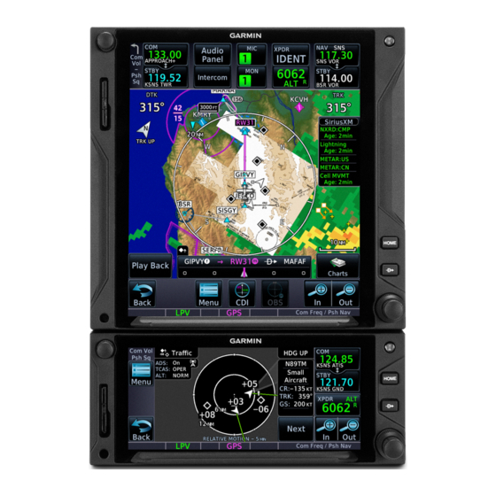
• Control for closing the pop-up window 2. Traffic alerts • Direct access to the associated page GTN 750Xi Series GTN 650Xi Series Terrain Pop-up Alert Layout Enlarged Page View Go to Terrain Page Key Threat Indication Alert Inhibit Key... - Page 129 Get Started GTN 750Xi Series GTN 650Xi Series Traffic Pop-up Alert Layout Enlarged Page View Go to Traffic Page Key Threat Indication Mute Alert Key Close Pop-up Window Key To open the indicated page, tap Go to <Page>. To acknowledge the alert and return to previous page view, tap Close.
-
Page 130: Aural Alerts
Get Started Aural Alerts Some alerts are accompanied by an aural voice message. Voice gender is configured during installation. To determine which alerts provide aural indications, refer to the applicable alerts table(s) in the Hazard Awareness section. MUTE ALERT FEATURE LIMITATIONS •... -
Page 131: Gps Status
Get Started GPS Status Monitor GPS receiver performance, establish a baseline for normal system operation, and troubleshoot weak or missing signal issues. This page provides a visual reference of GPS receiver functions, including: • • Current satellite coverage GPS solution and receiver status •... - Page 132 Get Started SIGNAL STRENGTH INDICATIONS A graph shows GPS signal strength for Satellite SVIDs up to 15 satellites. As the GPS receiver Each bar is labeled with the SVID locks onto satellites, a signal strength of the corresponding satellite. bar appears for each satellite in view. Numbers vary according to Graph symbols depict the progress of satellite type.
-
Page 133: Circle Of Uncertainty
Get Started POSITION ACCURACY FIELDS Information fields indicate the LABEL POSITION DATA accuracy of the position fix. Estimated Position Uncertainty HFOM and VFOM values represent 95% confidence levels HDOP Horizontal Dilution of Precision in horizontal and vertical HFOM Horizontal Figure of Merit accuracy. -
Page 134: Sbas Providers
Get Started SBAS Providers NOTE Operating with SBAS active outside of the service area may cause elevated EPU values to display on the status page. Regardless of the EPU value displayed, the LOI annunciation is the controlling indication for determining the integrity of the GPS navigation solution. SBAS supports wide area or regional augmentation through the use of additional satellite broadcast messages. -
Page 135: Gps Alerts
Get Started GPS Alerts The following alert conditions can affect GPS accuracy. INDICATIONS FAULT TYPE CONDITION Integrity of the GPS position does not meet the requirements for the Yellow “LOI” Loss of Integrity current phase of flight. Occurs annunciation. before the final approach fix (if an approach is active). -
Page 136: Lru Status
Get Started LRU Status Devices that interface to the system via Ethernet display product information and connection status on the External LRUs list. The device is configured and The device is not available and is communicating properly. not configured, or it is not communicating properly. -
Page 137: Logs
• Exports to the “logs” folder on the SD card • Streams logged flight and engine data to Garmin Pilot WAAS Diagnostic Log Functions • Records log files automatically while the unit is powered up • Overwrites oldest file when the internal log reaches capacity •... - Page 138 GDU streams data to Garmin Pilot via Flight Stream If Flight Stream is present in GTN: • GDU transfers logs to GTN, which then streams the data to Garmin Pilot via Flight Stream • GTN is the preferred location for Flight Stream installation If an SD card is present in GTN: •...
-
Page 139: Export To An Sd Card
Get Started Export to an SD Card NOTE Do not eject the SD card while the export function is in progress. Wait until the selected log key is available before ejecting the card. Export a flight data log to an SD card for later analysis. Home 1. - Page 140 Get Started TRANSFER SD CARD DATA TO YOUR ONLINE LOGBOOK The Logbook tab on flyGarmin.com provides functions for creating and viewing multiple logbook entries. flyGarmin Navigation Tabs To create a logbook: 1. Sign in to your flyGarmin.com account. 2. Select Logbook > Setup. 3.
-
Page 141: Streaming To Garmin Pilot
No need to worry. During flight, GTN Xi records log data to the internal storage. The next time you fly with your tablet, the data will stream to Garmin Pilot. This includes all previously recorded flights. The device downloads the data upon connecting to Flight Stream 510. - Page 142 INTENTIONALLY LEFT BLANK 2-98 Pilot’s Guide 190-02327-03 Rev. C...
-
Page 143: Navigation
3 Navigation MAP..........................3-4 CHARTS........................3-47 WAYPOINTS......................3-53 ACTIVE FLIGHT PLAN..................3-73 DIRECT TO......................3-110 PROCEDURES....................3-118... - Page 144 Navigation NAVIGATION APPS & FUNCTIONS Selections vary based on features and optional equipment installed with Garmin avionics. Charts • • Display moving map View terminal procedures & airport surface diagrams • Adjust detail level • Customize map overlay features •...
- Page 145 Activate a missed approach • Catalog & manage saved flight plans • Specify a parallel course offset • Import a flight plan GTN 650Xi SERIES Direct To Default NAV • Set a direct course to any • Configure user fields waypoint •...
-
Page 146: Map
Navigation To increase situational awareness, Map depicts the aircraft’s current position relative to land, aeronautical, weather, and traffic information. FEATURE REQUIREMENTS • Active GPS source (aircraft position symbol) • Active weather subscription (Connext & SiriusXM only) • FIS-B and GDL 88 or GTX 345 (FIS-B Weather) •... - Page 147 Navigation Default Map Features Ownship Icon Depicts current aircraft position and orientation. Track Vector Current ground track indication. Basemap Presents a graphical depiction of land and water data. User Field Customizable data field appearing in each corner of the map. NAV Range Ring Displays current direction of travel on a rotating compass.
- Page 148 Navigation Map Orientation Label Reflects the selected map orientation. Map Overlay Icons Indicates status of overlays at the current map range. Includes: obstacles, power lines, precipitation, terrain, and traffic Zoom Scale Displays the current magnification level. CDI & GPS Nav Status Indicator Lower bar presents a sliding lateral deviation indicator.
- Page 149 Navigation DATA DRAWING ORDER The electronic map draws data in order of priority, from highest (1) to lowest (36), with higher priority features drawn atop those of lower priority. LEVEL FEATURE LEVEL FEATURE Traffic County Warning Ownship PIREPs Flight Plan AIREPs TAWS Alerts City Forecast...
-
Page 150: Map Setup
Navigation Map Setup Overlay data controls reside in the Map Setup Tabs Map menu. Selections are organized into six groups. Aviation Changes to an overlay setting take effect Airspace immediately. Land Traffic Weather RESTORE DEFAULTS Map Setup Menu Located in the bottom of each list, this Orientation key restores all original factory settings North Up... -
Page 151: Map Display Orientation
Navigation Map Display Orientation Set the orientation of the map display. Tap Menu > Map Setup > Orientation, and select from the following options. North Up Track Up Heading Up Orients map to True Orients map to current Orients map to current north aircraft GPS track aircraft heading... -
Page 152: Visual Approach
Navigation Visual Approach Sets the distance from the destination airport at which the Visual Approach selector key becomes active. Visual Approach 3-10 Pilot’s Guide 190-02327-03 Rev. C... -
Page 153: Auto Zoom
Navigation Auto Zoom Automatically adjusts Map to display the next waypoint in flight plan at the closest possible map range. Automatic functionality is overridden during manual zoom interactions. It resumes when: • Another waypoint is in sequence • Aircraft transitions from on ground to airborne •... -
Page 154: Track Vector
Navigation Track Vector FEATURE LIMITATIONS • Indication absent when aircraft velocity is < 30 kt Indicates the current ground track. Arrow tip represents aircraft position at the specified time interval (if the aircraft maintains current ground track during that time). Track vector length options display as a dashed line and arrow extending from the aircraft icon, showing current track and distance the aircraft will travel in the selected time. -
Page 155: Glide Range Ring
Navigation Glide Range Ring FIXED WING AIRCRAFT ONLY FEATURE REQUIREMENTS • Datalink winds or compatible PFD (Glide Range Ring wind compensation) • For best glide performance, the aircraft must be configured in accordance with POH guidance Identifies map region and features within gliding distance. - Page 156 Navigation Ring Only Ring and Glide Glide Range Best Glide Ring Airport Indicator Enable Glide Range Ring to stay aware of all airports within gliding distance. This is extremely helpful should you experience engine failure. Best Glide Airport Indicator Glide Only Cyan arrows point toward the best glide airport at any given time.
- Page 157 Navigation “No Wind Data” Indicator This indication appears when FMS winds and datalink winds aloft are either unavailable or invalid. The Glide Range Ring does not adjust to account for current winds when the indicator is present. 190-02327-03 Rev. C Pilot’s Guide 3-15...
- Page 158 Navigation NEAREST AIRPORT GLIDE INDICATIONS Airports with the “Glide” designation are within line-of-sight of the aircraft and reachable on glide. The calculated best glide airports Best Glide appear at the top Airports of the list. An icon denotes which airports are reachable on glide.
-
Page 159: Nav Range Ring
Provides a more precise indication of distance between the aircraft and map objects. On Setting Enhanced Setting Fuel Range Ring FEATURE REQUIREMENTS • A Garmin EIS • Third-party fuel systems • Estimates the remaining range at the current fuel consumption rate and ground speed. -
Page 160: Topo Scale
Navigation TOPO Scale Displays a topographical elevation scale. To remove the scale, toggle TOPO Scale off. Scale Location Chart Color Scheme GTN 750Xi SERIES Toggles chart color scheme between day and night modes. Night 3-18 Pilot’s Guide 190-02327-03 Rev. C... -
Page 161: Selected Altitude Range Arc
Navigation Selected Altitude Range Arc FEATURE REQUIREMENTS • A Garmin Display Unit Represents location at which the aircraft is expected to reach selected altitude. 190-02327-03 Rev. C Pilot’s Guide 3-19... -
Page 162: Aviation Selections
Navigation Aviation Selections Setup options allow you to customize Aviation Menu the display of aeronautical information. Heliports • Enable heliports and TFRs SafeTaxi Diagrams • Specify airway types and range Runway Extensions values Intersection Range • Customize the display of SafeTaxi NDB Range VOR Range and waypoint data VRP Range •... - Page 163 Navigation AVIATION DATA SYMBOLS Non-towered, Non-towered, non-serviced airport serviced airport Towered, Towered, non-serviced airport serviced airport Soft surface, Soft surface, non-serviced airport serviced airport Restricted (private) airport Unknown airport Heliport ILS/DME or DME only Intersection TACAN VOR/DME VORTAC User Airport User Waypoint Runway extension Symbol depicts orientation of longest runway.
-
Page 164: Safetaxi
Navigation SafeTaxi SafeTaxi provides greater map detail and higher image resolution at lower zoom levels. Feature labels denote: Zoomed Out • Runways • Taxiways • Airport landmarks Zoomed In SafeTaxi Features • Airport diagram overlay that includes hot spot information •... - Page 165 Navigation HOT SPOTS SafeTaxi hot spots identify locations on an airport surface where positional confusion or runway incursions are likely to occur. These known problem areas require heightened attention by pilots. Selecting the border of a hot spot displays a brief summary of the indicated hazard and an information key.
-
Page 166: Airspace Selections
Navigation CONSTRUCTION SPOTS There are no expanded detail keys or notes associated with construction areas. Construction Area Border Airspace Selections Filter airspace data according to Airspace Menu altitude. The control for enabling smart airspace functionality also resides here. Airspace Label Range Smart Airspace With the exception of Smart Airspace, Show Airspaces all Airspace tab selections provide Select filter... -
Page 167: Smart Airspace
Navigation Smart Airspace Garmin’s Smart Airspace feature automatically de-emphasizes non-pertinent airspace away from the aircraft’s current altitude. When an airspace’s vertical proximity Smart Airspace off to the aircraft is >1,000 ft: • Its boundary becomes transparent • All associated altitude labels... -
Page 168: Land Selections
Navigation Land Selections Filter the display of land features according Land Menu to detail level. Road Detail With the exception of State Province Names, City Detail all Land tab selections provide detail setting State/Province Names options. River/Lake Detail Restore Defaults LAND DATA SYMBOLS Railroad National Highway River/Lake Freeway State/Province Border... -
Page 169: Traffic & Weather Selections
Navigation Traffic & Weather Selections TRAFFIC Filter traffic data according to type. Other Traffic Menu selections include on/off and range setting options. Traffic Range Traffic Type All Traffic Alerts & Advisories Alerts Only WEATHER Setup options are available for all active Datalink Weather Menu weather services. Weather Source • Specify a datalink weather source SiriusXM •... -
Page 170: Map Interactions
Navigation Map Interactions Basic Interactions Typical map interactions include zoom, pan, and object selection. PAN & ZOOM Panning allows movement of the map in any direction without change to the current zoom setting. Zooming adjusts the current magnification level between pre-defined range parameters. - Page 171 Navigation MAP INFO Available information and controls are dependent upon object or location type and proximity to other objects. Selecting an airport icon displays the airport’s highest field elevation. A map pointer icon corresponds with the touch point on the map. Selected Airport An information page access key displays when you select a...
- Page 172 Tapping Airspace Info opens the associated information page. Data fields display information specific to the selected airspace. GTN 650Xi SERIES Tapping Preview displays the airspace boundary and a 2D map of the surrounding area. DATA FIELDS CONTROLS •...
-
Page 173: Graphical Flight Plan Editing
Navigation Graphical Flight Plan Editing FEATURE LIMITATIONS • Parallel track offsets do not apply to the temporary flight plan Graphical editing allows quick changes to the active flight plan from the map display. Map provides identifier keys for selecting waypoints that are stacked or in close proximity. - Page 174 Navigation ADD WAYPOINT TO AN EXISTING LEG Existing Leg You can edit, add, or omit flight plan legs by tapping or dragging your finger directly on the map. Selected Waypoint 1. Tap any location on the map. 2. Tap Graphical Edit. 3-32 Pilot’s Guide 190-02327-03 Rev.
- Page 175 Navigation 3. Tap and drag the leg to a new waypoint or airway, then release. New Route The temporary flight plan adjusts to show the new route. If no other edits are necessary, tap Done. The new waypoint now appears in the active flight plan.
- Page 176 Navigation Active Leg Active route identifiers also appear on the GPS NAV status indicator. If configured, a user field shows active route identifiers on Map. Delete any existing flight plan before attempting to graphically edit a direct-to waypoint. Map does not allow the addition of an intermediate waypoint between the current position and a direct-to waypoint unless the waypoint is in the flight plan.
- Page 177 Navigation REMOVE WAYPOINT FROM FLIGHT PLAN You can tap and drag any leg to another waypoint or airway, or release it away from any waypoint if an alternate destination is not preferred. CREATE LEGS WITHOUT AN EXISTING FLIGHT PLAN If an active flight plan does not exist, you can graphically create one without ever leaving Map.
-
Page 178: Map Overlays
Navigation Map Overlays Overlay data controls reside in the Map Overlay Selections menu. Changes to an overlay setting • • take effect immediately. TOPO Charts • • Terrain Stormscope NEXRAD and Terrain overlays are mutually exclusive. Enabling one • • Traffic Airways automatically disables the other. - Page 179 Navigation TERRAIN • Overlays terrain map data • Color shading depicts terrain elevation relative to the aircraft’s altitude TRAFFIC • Overlays traffic information • Filter selection on the Traffic page determines altitude range • Feature optional NEXRAD • Overlays datalink precipitation weather information •...
- Page 180 Navigation CHARTS • Overlays geo-referenced chart information • Approach chart for the active flight plan in the navigator • Airport surface chart if nearest airport is within 200 nm and no approach is active • Depicts planview area only; excludes inset information (e.g., missed approach procedure view) Arrival and departure chart overlays are not...
- Page 181 Navigation AIRWAYS • Overlays the selected airway type(s) with identifier labels • Options include: low, high, all, or off (none) • High altitude airways are green, low altitude airways are gray RADAR • Overlays airborne weather radar information • Depictions are identical to those on the Weather Radar display •...
-
Page 182: Overlay Status Icons
Navigation Overlay Status Icons Icons indicate which overlays are present at the current map range. A crossed out icon means the overlay is active, but data is unavailable due to a failure, test, or standby condition (where relevant). The absence of an overlay icon means one of two possible conditions: 1. -
Page 183: User Fields
Navigation User Fields User fields allow you to customize the display of data in each corner of the map. Tap Change User Fields to access available options. In configuration mode: • All four data fields change to selectable keys • All other map elements are inactive Tap a key and select from the... - Page 184 Navigation Data Tab Options: Available field types and their corresponding labels are as follows: 4, 7 ACTV WPT Active waypoint NAV/COM Active NAV/COM frequency Bearing to waypoint OAT (static) Outside static air temperature Distance/bearing from D/B APT destination airport (i.e., the OAT (total) Outside total air temperature straight line distance)
- Page 185 To view this field, turn off TOPO Scale (Tap Menu > Map Setup > TOPO Scale). TOPO scale off TOPO scale on User Field Absent Available when TAWS-A is active. Available when HTAWS is active. GTN 750Xi series units only. GTN 650Xi series units only. 190-02327-03 Rev. C Pilot’s Guide 3-43...
- Page 186 DTK - Desired Track • TRK - Track • BRG - Bearing User fields are useful during time • ETE - Estimated time en route sensitive and work load intense phases of flight. GTN 650Xi Series only. 3-44 Pilot’s Guide 190-02327-03 Rev. C...
- Page 187 You can access these fields from the System menu. Home > System > User Fields GTN 650Xi SERIES You can also configure user fields for display on the Default Navigation page. Options are identical to those available on Map.
-
Page 188: Map Detail
Navigation Map Detail Changes to the map detail level take effect immediately. There are four levels from which to choose. FEATURE FULL HIGH MEDIUM Small Cities • Medium Cities • Large Cities • Freeways • Highways • Roads • Railroads •... -
Page 189: Charts
Navigation Charts The Charts page provides terminal procedures and airport surface diagrams. FEATURE REQUIREMENTS • A current and valid chart database FEATURE LIMITATIONS • Geo-referencing is not available for some arrival and departure charts • FliteCharts and ChartView databases are optional and mutually exclusive Chart Window Selection Controls Chart... - Page 190 Navigation CHARTVIEW INFORMATION SECTIONS Header Planview Profile Minimums CHART STATUS Active chart status displays at the bottom of the Charts display. Charts are in the process up updating. Charts are up to date. Database is out of date. Database is installed before it is current. 3-48 Pilot’s Guide 190-02327-03 Rev.
-
Page 191: Chart Setup
Navigation Chart Setup Tap Menu to access setup selections. Charts Menu From here you can: Chart Information • View individual chart sections (ChartView only) Header • Plan Change the chart’s color scheme for Profile day or night viewing Minimums Chart Color Scheme Night [1] ChartView only. Displays individual sections of a chart in the ChartView database only. -
Page 192: Chart Selection
Navigation Chart Selection To select a chart: 1. Tap Airports. 2. Enter an airport identifier. 3. Choose from the available chart types. CHART TYPES Approach All approach charts associated with the selected airport. Charts are listed according to level of precision and approach type. - Page 193 Navigation AUTOMATIC CHART SELECTION Automatic chart selection occurs every time the Charts page is opened. The type of chart selected is determined by aircraft status and content from the active flight plan. This function does not override manual chart selections unless a change occurs during one of the following conditions.
-
Page 194: Aircraft Position Icon
Navigation Aircraft Position Icon FEATURE REQUIREMENTS • Aircraft position is fully within chart boundaries • FliteCharts or ChartView is active (airborne maneuvers only) FEATURE LIMITATIONS • SIDs and STARs do not support the display of aircraft position • Not available for arrival and departure charts •... -
Page 195: Waypoints
Navigation Waypoints There are two types of waypoints: database and user Database waypoints (i.e., waypoints contained in the navigation database) are organized into the following groups. • Airport (APT) • Intersection (INT) • Very High Frequency Omni-directional Range (VOR) • Visual Reporting Point (VRP) •... -
Page 196: Waypoint Information
Navigation Waypoint Information Dedicated information pages provide waypoint search functions and details not available on Map. FEATURE REQUIREMENTS • FIS-B (viewing NOTAMs) • Navigation database containing VRP waypoint data FEATURE LIMITATIONS • FIS-B transmits distant and FDC NOTAMs within 100 nm of radio station position Intersection, VOR, VRP, and NDB information pages have a uniform layout. -
Page 197: Common Page Features
• Identifier and type icon MAP PREVIEW WINDOW A 2D map of the surrounding area (includes SafeTaxi airport depictions). GTN 650Xi SERIES Tapping Preview displays the waypoint location on a dedicated map page. As you approach an airport, use the map preview function to orient yourself for such things as pattern entry or runway alignment. -
Page 198: Waypoint Specific Page Features
Navigation Waypoint Specific Page Features The following features are unique to the corresponding waypoint. Airport Selectable tabs: Info: Airport location, elevation, time zone, and fuel availability. Procedures: Available approach procedures. Runways: Identifiers, size, surface type, and traffic pattern direction. Tapping Runway opens a list of available runways. - Page 199 Navigation Non-Directional Beacon Data fields: • Frequency • Nearest airport (identifier, type icon, bearing, and distance) • Marker description User Waypoint Selectable functions: Edit: Opens the Create User Waypoint page for editing purposes. View List: Displays a list of all user waypoint identifiers. Delete: Removes the selected user waypoint from the list.
-
Page 200: Waypoint Selection
Navigation Waypoint Selection The Waypoint Identifier key provides access to different waypoint search options. Enter a specific identifier or select one from the available search tabs. Waypoint Autofill Autofilled As you type the identifier name, Character alphanumeric characters autofill based on the first alphabetical match in the navigation database. -
Page 201: Fastfind Predictive Waypoint Entry
Navigation FastFind Predictive Waypoint Entry FastFind predicts a waypoint based on the characters you select. As you type, the key label changes to reflect the identifier of the nearest matching entry. Tap to select the predicted waypoint and open the corresponding information page. Because it relies on your GPS position, FastFind can make predictions based on a single key press. -
Page 202: Search Tabs
Navigation Search Tabs The Find key provides access to multiple search tabs. Each tab displays a list of selectable identifiers based on specific criteria. These include: • Recent • Nearest • Flight Plan • User • Search Name • Search City Waypoint Search Tabs Waypoint Each entry includes general... - Page 203 Navigation FLIGHT PLAN Lists all waypoints contained in the active flight plan. USER Lists up to 1,000 user-defined waypoints. SEARCH BY NAME/CITY Search By Name Search By City Lists all airports, NDBs, and VORs Lists all airports, NDBs, and VORs associated with the specified found in proximity of the city.
-
Page 204: Create User Waypoints
Navigation Create User Waypoints Create and store up to 1,000 user defined waypoints. FEATURE LIMITATIONS • Duplicate user waypoint identifiers are not allowed • Names may be up to six characters in length • Comment may be up to 25 characters •... - Page 205 Navigation USER WAYPOINT IDENTIFIER Assign a unique identifier or keep the unit generated identifier. If an identifier is already in use, the three digit number increments automatically upon opening the page. User Waypoint User Airport By default, the identifier format is Identifier format is “A”...
-
Page 206: Define Waypoint Criteria
Navigation Define Waypoint Criteria Active user waypoints already existing in a Create Waypoint Options flight plan are not editable. User Identifier When creating a user waypoint, you have Specify identifier the option to: Airport • Assign a unique identifier Specify elevation • Set the waypoint as temporary Comment •... - Page 207 Navigation COMMENT FORMAT Default comments display in a specific format for each reference type. LAT/LON Radial/Distance <LAT> <LON> <Waypoint><Radial> / <Distance> Radial/Radial <Waypoint 1><Radial 1> / <Waypoint 2><Radial 2> POSITION TYPE Set the waypoint position type using one of the following options. Radial/Radial Radial/Distance LAT/LON...
-
Page 208: Create A User Waypoint
Navigation Create a User Waypoint OPEN CREATE USER WAYPOINT PAGE From Map: Home > Map > select any non-waypoint location > Map Pointer/Create Waypoint From Waypoint Info: Home > Waypoint Info > Create Waypoint ASSIGN POSITION VALUES From the Create User Waypoint page: 1. -
Page 209: Edit An Existing User Waypoint
Navigation Edit an Existing User Waypoint FEATURE LIMITATIONS • User waypoints that are part of a flight plan or direct course are not editable ACCESS USER WAYPOINT EDIT OPTIONS You can access the edit function multiple ways. From the dedicated information page: Home >... -
Page 210: Delete User Waypoints
Navigation Delete User Waypoints FEATURE LIMITATIONS • User waypoints that are part of a flight plan or direct course cannot be deleted You can delete a user waypoint from its information page: 1. Select the user waypoint, then tap Delete. 2. -
Page 211: Import User Waypoints
Navigation Import User Waypoints The Import Waypoints key appears when the unit detects a user waypoint on the datacard. NOTE The import function overwrites any existing user waypoint of the same name. FUNCTIONAL LIMITATIONS • User waypoint file size must not exceed 8 GB CREATE USER WAYPOINT FILE You may create a list of new user waypoints using any spreadsheet program. - Page 212 Navigation User Waypoint File Considerations • Limit one waypoint per row • Names may be up to six characters in length • Comments may be up to 25 characters • All letters must be upper case • Latitude: two digits left of decimal; up to nine digits right of decimal •...
-
Page 213: Nearest
Navigation Nearest View a list of the nearest waypoints, frequencies, or facilities within 200 nm of the aircraft’s position. From the Home page: 1. Tap Nearest and then select a waypoint or frequency icon. 2. Scroll through the list of entries. Information varies according to the selected waypoint or frequency type. - Page 214 Navigation Nearest Airspace • identifier • symbol • proximity Nearest Air Route Traffic Control Center • facility name • distance • bearing • frequency Nearest Flight Service Station • facility name • distance • bearing • frequency (“RX” denotes receive-only frequencies) Nearest Weather Frequency •...
-
Page 215: Active Flight Plan
Navigation Active Flight Plan Current flight plan information displays as a scrolling list on the Active Flight Plan (FPL) app. FEATURE REQUIREMENTS • Active flight plan FEATURE LIMITATIONS • Displays up to 99 waypoints for an active flight plan Active Flight Plan Selectable Data Field Current Waypoint Columns... - Page 216 Navigation AIRPORT INFO Procedure Airport Info For convenience, airport Header information is directly accessible from the procedure header. This includes airports specified in active approaches, arrivals, and departures. Tap Airport Info to open the corresponding information page. FIX TYPE INDICATIONS When applicable, labels indicate LABEL FIX TYPE...
- Page 217 Navigation ACTIVE LEG STATUS INDICATIONS Magenta symbols denote active leg status on from/to/next waypoint indications. Fix type symbols (e.g., FAF, MAP) correspond with labels appearing on the flight plan. Arc Left Holding Pattern (Right Turns) Holding Pattern (Left Turns) MAHP Active Leg Arrow Parallel Track Direct To...
-
Page 218: Create A Flight Plan
Navigation Create a Flight Plan NOTE The unit cannot verify the accuracy of cataloged flight plans with modified procedures. There are three methods for creating a new flight plan. CREATE FROM THE ACTIVE FLIGHT PLAN PAGE 1. Tap Flight Plan. 2. -
Page 219: Airway Options
Navigation Airway Options Selecting an airway from the active flight plan Airway Options opens a menu. You may elect to: Collapse All Airways • Collapse all legs of the airway Select Airway • Select a new airway Remove Airway • Remove an airway from the flight plan Collapse All Airways Airways automatically display as flight plan legs. -
Page 220: Sort Airways
Navigation Sort Airways Preview of a sorted airway waypoint list. A toggle key allows you to sort the airway waypoint list alphabetically or by distance. This option is available once you select an airway. The sort function is useful when you are searching for an exit point from the airway. -
Page 221: En Route Vertical Navigation
Navigation En Route Vertical Navigation Create a vertical navigation (VNAV) path with multiple altitude constraints in the flight plan. WARNING Do not rely solely on VNAV guidance when navigating horizontally and vertically around user-defined airports. It is the pilot's responsibility to ensure separation from terrain and obstacles during an approach to a user-defined airport. -
Page 222: Define A Vnav Profile
Navigation Define a VNAV Profile Active vertical navigation profile information displays on the VNAV Profile page. From here you can: • Enable en route vertical guidance • Specify a target vertical speed and flight path angle • View active constraint data •... -
Page 223: Altitude Constraints
Navigation Altitude Constraints Altitude constraints are either entered manually into the active flight plan, or automatically retrieved from the published altitudes in the navigation database. GTN automatically uses altitudes loaded with arrival and approach procedures (up to and including the FAF) for computing vertical deviation guidance. Altitude constraints loaded from the database are jet altitudes. - Page 224 Navigation ALTITUDE TYPES Database Constraint Altitude is retrieved from the navigation database and designated for use in determining vertical guidance. Pilot-specified Constraint Pencil icon indicates manual designation or manual data entry. Invalid Altitude Constraint GTN cannot use the altitude to determine vertical guidance. Estimated Crossing Altitude For reference only.
- Page 225 Navigation INVALID ALTITUDE CONSTRAINTS An altitude constraint is invalid if: • Meeting the constraint requires the aircraft to climb • Meeting the constraint requires the aircraft to exceed the maximum flight path angle (6° downward) or maximum vertical speed (-4,000 fpm) •...
- Page 226 Navigation Designate a waypoint altitude for use with vertical guidance: 1. Select a waypoint altitude constraint. 2. Tap Save. Enter or modify an altitude constraint: 1. Select an altitude constraint. 2. Tap Type and select the constraint type. 3. Select the altitude data key. 4.
-
Page 227: Vnav Direct To
Navigation VNAV Direct To This function creates a vertical navigation path from the aircraft’s current position and altitude to a selected waypoint’s location and altitude. By removing any VNAV constraints between the aircraft and selected waypoint, it allows you to fly the lateral flight plan in a continuous descent and reach the waypoint at the specified altitude. -
Page 228: Temperature Compensated Altitude
Navigation Temperature Compensated Altitude NOTE GTN and TXi displays use a single destination airport temperature for calculating compensated altitudes. Changing the temperature on one of these units automatically recalculates the value across all connected GTNs and GDUs. FEATURE REQUIREMENTS • Active flight plan contains a destination airport •... -
Page 229: Obs
Navigation The Omni Bearing Selector (OBS) allows you to select between manual or automatic sequencing of waypoints. When active, this function allows you to set the desired course To/From a waypoint using the provided controls or with an external OBS selector on HSI or CDI. -
Page 230: Dead Reckoning
Navigation Dead Reckoning WARNING Do not use projected position data as the only means of navigation. Points About Dead Reckoning • Provides limited navigation using the last known position and speed following the loss of GPS navigation while on an active flight plan •... -
Page 231: Parallel Track
Navigation Parallel Track Create a parallel course offset relative to the current flight plan. Setup controls provide offset distance and direction setting (left of track or right of track). FEATURE REQUIREMENTS • An active flight plan FEATURE LIMITATIONS • Function not available when Direct-to is active. •... - Page 232 Navigation Offset Offset Distance From Offset From ACTIVATE A PARALLEL TRACK 1. Tap Menu > Parallel Track. 2. Tap Offset and specify a distance between 1 nm and 99 nm. 3. Tap Direction and select left of track or right of track. 4.
-
Page 233: Invert Flight Plan
Navigation Invert Flight Plan Reverse the active flight plan and use it for navigation guidance back to your original departure point. Inverting the flight plan does not affect the original version stored in the catalog. Be aware that inverting a flight plan removes all ATKs. INVERT THE ACTIVE FLIGHT PLAN Tap Menu >... -
Page 234: Flight Plan Catalog
Navigation Flight Plan Catalog Create, activate, edit, copy, and delete flight plans within the catalog. FEATURE LIMITATIONS • Stores up to 99 flight plans with a maximum of 100 waypoints each Departure Destination Each catalog entry includes the identifiers of the departure and destination waypoints. -
Page 235: Catalog Route Options
Navigation Catalog Route Options Selecting a flight plan opens a menu. Changes to Route Options the active flight plan take effect immediately. Activate • Activate the selected flight plan Invert & Activate (replacing the active flight plan) Preview • Reverse and activate the selected flight plan Edit •... - Page 236 Navigation EDIT Modify the selected flight plan on the Edit Catalog Flight Plan page. COPY Create a copy of the selected flight plan. A copy may be used as a starting point for creating a similar flight plan. Select the copy and tap Edit to make modifications. DELETE A FLIGHT PLAN Deleting the active flight plan does not delete the stored flight plan in the catalog.
-
Page 237: Flight Plan Waypoint Options
Navigation Flight Plan Waypoint Options Selecting a waypoint identifier opens a menu. Options Menu Changes to the active flight plan take effect immediately. Activate Leg • Change the active leg Insert Before • Insert After Insert a new waypoint into a flight plan Along Track •... -
Page 238: Import A Flight Plan
Import Options You can import flight plans wirelessly from Garmin Pilot or from an SD card. Once imported, they may be previewed and then stored in the catalog or activated. IMPORT USING CONNEXT On your portable device: Select the option to transfer the flight plan(s) to GTN. -
Page 239: Potential Import Errors
Navigation Potential Import Errors Pop-up messages alert you when an import problem occurs. Tapping Next advances through multiple error messages. Tapping OK acknowledges the error and closes the popup. The following errors can prevent GTN from successfully importing your flight plans. Full catalog. - Page 240 Navigation CREATE AN ATK From the active flight plan: 1. Select a reference waypoint. 2. Tap Along Track and specify an offset distance. 3. Choose Before or After. 4. Tap Enter. CREATE AN ATK FOR AN ALTITUDE CONSTRAINT From the active flight plan: 1.
-
Page 241: User Holds
Clearance (EFC) Accept the specified hold parameters and return to the Load Hold previous window. View the defined holding pattern as it will appear on Map. Preview Available on GTN 650Xi Series units only. 190-02327-03 Rev. C Pilot’s Guide 3-99... - Page 242 A window displays the defined holding pattern on a 2D map of the surrounding area (includes SafeTaxi depictions). GTN 650Xi SERIES Tapping Preview displays the hold on a dedicated map page. You may view and load the hold, or return to the setup menu for more options.
-
Page 243: Search And Rescue Patterns
Accept the specified pattern and return to the previous Load Pattern window. Load Pattern & Accept and activate the specified pattern. Activate View the defined SAR pattern as it will appear on Map. Preview Available on GTN 650Xi Series units only. 190-02327-03 Rev. C Pilot’s Guide 3-101... - Page 244 A window displays the defined pattern on a 2D map of the surrounding area (includes SafeTaxi depictions). GTN 650Xi SERIES Tapping Preview displays the pattern on a dedicated map page. You may view and load the pattern, or return to the setup menu for more options.
-
Page 245: Sar Flight Plan Options
Navigation SAR patterns SAR Pattern begin with an Indication indicator field and end with an exit identifier. Expanded To activate a Pattern Detail pattern leg, select the leg and then tap Activate Leg. SAR Flight Plan Options Selecting a search pattern indicator from the Search & Rescue Options active flight plan opens a menu. -
Page 246: Flight Plan Map Overlays
Navigation Flight Plan Map Overlays Leg Status Indications Active, next, and previous flight plan legs LEG STATUS COLOR overlay on Map and are display only. Active Magenta Next & Future White Past or Inactive Gray Status leg indications. Next Leg(s) Active Leg Previous Leg(s) 3-104... -
Page 247: Along Track Offset Indications
Navigation Along Track Offset Indications Map indications include a dedicated icon and an identifier label. Identifier labels on Map denote the adjacent waypoint’s ID and offset distance from the specified ATK. Selecting an ATK displays its bearing and distance in the info banner. Waypoint ID Offset Distance ATK Icon... -
Page 248: Altitude Constraint Labels
Navigation Altitude Constraint Labels Altitude constraint data display as text labels on the Map. Units are typically feet or meters depending on current altitude setting in the System Units. They display as flight level altitudes if specified as such on the navigator. If excessive labels are cluttering the map, this feature may be turned off. -
Page 249: User Airport Icon
Navigation User Airport Icon A dedicated icon indicates user created airport waypoints. User airport indications display on Active Flight Plan and Map. When selected, the user identifier annunciates in the info banner. Identifier Type Icon Selected User Airport User Identifier 190-02327-03 Rev. -
Page 250: Cdi
Tapping Activate GPS Missed Approach only resumes automatic waypoint sequencing. To switch to GPS navigation, use your external source selection method (this is typical of an EFIS system). GTN 650Xi SERIES CDI scales display on the Default Navigation page (Home > Default NAV). -
Page 251: Gps Nav Status Bar
From, to, and next waypoints • Leg and waypoint types • Identifier GTN 650Xi SERIES This indicator is a feature of the Default Navigation page (Home > Default NAV). GTN 750Xi SERIES GPS Nav status indications appear at the bottom of the map display as part of the CDI. -
Page 252: Direct To
Navigation Direct To Set a course to any waypoint using Direct To. FEATURE LIMITATIONS • Not all flight plan entries are selectable using Direct To (e.g., holds, course reversals) • Available search and rescue patterns are dependent upon configuration. Direct To Basics Pushing this bezel key opens a slide-out window. -
Page 253: Direct To Search Tabs
Navigation Direct To Search Tabs WAYPOINT Similar to an information page, but with course and hold options. This tab is active by default. Selecting an identifier automatically displays the following information about the waypoint. • Identifier and type icon • Applicable city, state, country and/or region (e.g., “NW USA”) •... -
Page 254: Direct To Activation
Navigation FPL & NRST APT FPL and NRST APT tabs provide a list of selectable identifiers. These tabs have a uniform layout. Lists all waypoints contained in Lists up to 25 waypoints within the active flight plan. a 200 nm radius. The closest airport appears at the top of the list. - Page 255 Navigation ACTIVE FIX INDICATIONS Upon activation, Map automatically opens to show a graphical representation of the active direct-to leg. GPS Nav Status Bar GPS navigation status changes to show the active direct-to fix. Indication includes the corresponding fix symbol and waypoint identifier. Map User Field Active Flight Plan Indication If configured, a user field shows...
-
Page 256: Navigating Direct To
Navigation Navigating Direct To While most direct-to operations follow the same basic steps, the method for selecting a waypoint may vary. DIRECT TO A NEW WAYPOINT 1. Tap Direct To. 2. Select a waypoint identifier. 3. Tap Course and specify the course heading (if a specific course is necessary). 4. -
Page 257: Remove A Direct Course
Navigation DIRECT TO AN OFF-ROUTE COURSE You may activate an off-route course using any of the described direct-to methods. Activating an off-route direct course automatically deactivates the current leg of the active flight plan. Direct To & Procedure Fixes Approach guidance is not available for procedure fixes. -
Page 258: User Holds
Navigation User Holds Define a holding pattern for any direct-to waypoint. Tapping Hold displays available Loading the specified hold hold options. parameters returns you to the Direct To window. The Hold key label changes to reflect the specified course angle. CREATE &... -
Page 259: Search And Rescue Patterns
Navigation Search and Rescue Patterns Create a search and rescue pattern for any direct-to waypoint. Tapping SAR displays options Loading a pattern returns you for defining a search and rescue to the Direct To window. The pattern for the direct-to SAR key label changes to reflect waypoint. -
Page 260: Procedures
Navigation Procedures Lateral and vertical guidance is available for visual and GPS/RNAV approaches. The published instrument approach procedures allow precision and non-precision approaches to airports. These are directly accessible via the Procedures app. FEATURE REQUIREMENTS • Baro-corrected altitude source (automatic sequencing of altitude leg types) In the absence of baro-corrected altitude data, altitude leg types require manual sequencing. -
Page 261: Flight Procedure Basics
Navigation Flight Procedure Basics WARNING Do not rely solely on VNAV guidance when navigating horizontally and vertically around user-defined airports. It is the pilot's responsibility to ensure separation from terrain and obstacles during an approach to a user-defined airport. NOTE Advisory climb altitudes for SIDs may not match charted altitudes. - Page 262 Navigation Roll Steering When switching the CDI source from GPS to VLOC during ILS, VOR, NDB, and non-precision localizer-based approaches, roll steering terminates when approach mode is selected on the autopilot. It becomes available once you initiate the missed approach. TO/FROM LEGS ON CDI TO Legs FROM Legs...
-
Page 263: Localizer Or Vor-Based Approaches
Navigation Localizer or VOR-based Approaches GTN automatically switches the external CDI output from GPS to VLOC as you intercept the final approach course. When the ILS approach activates and the correct ILS frequency activates in the VLOC window, the GTN automatically switches to VLOC within 1.2 nm left or right of the final approach course. -
Page 264: Gps Flight Phase Annunciations
Navigation GPS Flight Phase Annunciations Flight Phase Check the annunciator bar for (Caution) current phase of flight. Map complements your printed approach plates by improving situational awareness during the approach. It does not replace printed approach plates. Always fly an approach as it appears on the approach plate. Under normal conditions, these annunciations are green. - Page 265 Navigation ANNUNCIATION FLIGHT PHASE Low Altitude • Aircraft’s estimated height is lower than the final approach waypoint height by approximately 50 meters LOW ALT • For LNAV+V, LNAV/VNAV, LP +V, or LPV approaches • Not active when terrain alerting functions are operational Localizer Performance Approach •...
-
Page 266: Departures
Navigation Departures Loading a Departure into Flight Plan • Flight plans allow only one departure procedure at a time • Loading a departure when one is already present will replace the existing entry • Selecting a departure, transition waypoint, and runway defines the route FEATURE LIMITATIONS •... -
Page 267: Arrivals
Navigation Arrivals Loading an Arrival into Flight Plan • Load a Standard Terminal Arrival (STAR) at any airport with a published arrival procedure • Flight plans allow only one arrival procedure at a time • Loading an arrival when one is already present will replace the existing entry •... -
Page 268: Approaches
Navigation Approaches Loading an Approach into Flight Plan • Always check the runway, transition, and all waypoints • Flight plans allow only one approach procedure at a time • You may load an alternate approach during a missed approach procedure (flight plan retains all missed approaches) •... - Page 269 Navigation SBAS APPROACHES To load an SBAS approach: Channel ID Key 1. Tap Channel/ID. • Select the channel ID for an 2. Specify an approach channel. SBAS approach to the current If present, both channel and ID load destination automatically. •...
-
Page 270: Flight Plan Approach Options
Navigation PROCEDURE TURNS A procedure turn is stored as another Roll Steering & approach leg. It does not require any Procedure Turns special operations other than flying the procedure itself. The steering provided for a procedure turn does not guarantee Roll steering is available for aircraft that the aircraft will with a compatible autopilot. -
Page 271: Missed Approach
Navigation Missed Approach The method for activating a missed approach depends on your position in relation to the missed approach point. BEFORE MISSED APPROACH POINT Select Activate Missed Approach. This function is available in two applications: Active FPL: Home > Flight Plan > Select the approach > Activate Missed Approach Procedures: Home >... -
Page 272: Approach Hold
Navigation Approach Hold Published holds display on the flight plan one of two ways: with an exit leg or without. Most published holds have three distinct legs. Hold Entry Leg Hold Leg Hold Exit Leg This leg is active prior This leg is active after crossing This leg is active when to crossing the hold... - Page 273 Navigation FLIGHT PLAN APPROACH HOLD OPTIONS Selecting an approach hold on the flight plan opens a Hold Options menu. Changes to the active flight plan take effect immediately. Activate Hold Insert After • Activate the selected hold Edit Hold • Insert a waypoint after the hold Exit Hold •...
- Page 274 Navigation NON-REQUIRED HOLDING PATTERNS Upon activating an RNP GPS approach, decide whether to skip non-required holding patterns during the initial transitions of the approach. A pop-up presents two options. Selecting Yes adds the hold to the flight plan. Preview shows the hold in white. Selecting No means the hold is not included in the flight plan.
-
Page 275: Dme Arc
Navigation DME Arc The unit supports approaches DME Arc Approaches containing DME arcs. • Left/right guidance relative to To manually activate DME Arc, the arc the aircraft must be within the • Manual arc leg activation shaded area. once aircraft is near the arc DME Arc Intermediate Initial... -
Page 276: Rf Legs
Navigation RF Legs The unit supports radius-to-fix (RF) AC 90-101A - RF Legs legs associated with RNAV RNP 1.0 AC 90-101A defines RF leg as non-AR approaches, when approved by “A constant radius circular path, the installation. around a defined turn center, that Flying a radius-to-fix approach is similar starts and terminates at a fix. -
Page 277: Ils Approach
Navigation ILS Approach NOTE ILS and LOC approaches are not approved for GPS. GPS guidance is for monitoring purposes only. Selecting an ILS or LOC approach results in a pop-up message. Activate the approach or select a different one. Do not attempt to use the unit as the primary navigation source during ILS approach. RNAV Approaches Fly RNAV approaches according to Always fly to the published... - Page 278 Navigation LNAV APPROACH RNAV non-precision lateral navigation approach. LNAV+V APPROACH RNAV non-precision LNAV approach with advisory vertical guidance. The glidepath is a light dashed line on the vertical profile (Jeppesen charts only) with an associated glidepath angle (usually in the 3.00 degree range) to assist in maintaining a constant vertical glidepath, similar to an ILS glideslope.
- Page 279 Navigation LPV APPROACH Localizer performance with vertical guidance. Similar to flying the standard ILS approach. This segment describes a typical LPV approach sequence and the necessary pilot actions. Within 31 nm of destination: • Mode switches from En Route to Terminal •...
- Page 280 Navigation If GPS integrity exceeds the horizontal and/or vertical alarm limits: • Approach downgrades to non-precision • “LNAV” annunciates on Map to inform of the change if there are LNAV minimums for the approach • Advisory message: ”GPS approach downgraded. Use LNAV minima.” •...
- Page 281 Navigation LP APPROACH Points About LP Approaches • Use SBAS accuracy, making them similar to an LNAV approach but more precise • Combine the lateral accuracy of an LPV approach with the angular scaling of a localizer approach • Often contain step-down altitudes •...
- Page 282 Navigation If pilot exceeds the horizontal alarm limits: • Approach downgrades to non-precision • “LNAV” annunciates on Map to inform of the change • Advisory message: “GPS approach downgraded. Use LNAV minima.” • Pilot continues approach using LNAV non-precision minimums, if applicable If GPS integrity does not meet the non-precision horizontal alarm limits: •...
- Page 283 Navigation Crossing missed approach point: • Sequencing suspends • Pop-up message: “Missed Approach Waypoint Reached” • Pilot decides whether to remain suspended or activate the missed approach • Tapping Remain Suspended allows you to continue with sequencing suspended • Tapping Activate GPS Missed Approach allows you to continue with guidance to the missed approach hold point Prepare aircraft for missed approach operation: •...
-
Page 284: Visual Approach
Navigation Visual Approach Points About Visual Approaches • Provide advisory horizontal and optional vertical guidance for the selected runway • Lateral guidance is always provided for visual approaches • Helps stabilize the runway approach • Three methods for loading and activation FEATURE REQUIREMENTS •... - Page 285 Navigation LOAD A VISUAL APPROACH FROM MAP When the aircraft is within 10 nm of the destination airport, the Visual Approach selector key becomes active. This key may appear in one of two places: On the map or at the left of the screen if the supporting airport is selected. 1.
-
Page 286: Autopilot Outputs
Navigation Autopilot Outputs CAUTION Engage the autopilot heading mode and set the heading bug appropriately to use the autopilot on heading legs using the autopilot’s NAV, GPSS, or APR mode. Not all autopilots follow guidance on these leg types, Some revert to a roll only or wings level mode. - Page 287 4 Planning VCALC ..........................4-4 TRIP PLANNING .....................4-7 FUEL PLANNING ....................4-11 DALT/TAS/WIND CALCULATOR ..............4-15 RAIM PREDICTION..................... 4-18 CHECKLISTS......................4-20...
- Page 288 Planning PLANNING APPS & FUNCTIONS The following features make flight planning easier and more efficient. VCALC Trip Planning Input: Input: • • Target Altitude Route • • Altitude Profile Depart Date/Time • • Target Waypoint Ground Speed GTN computes: GTN computes: •...
- Page 289 Planning Fuel Planning DALT/TAS/Winds Input: Input: • • Route Air Data • • Fuel Data Track • • Ground Speed Heading • Ground Speed GTN computes: GTN computes: • • Fuel Required Density ALT • • Reserve • • Range Wind Direction •...
-
Page 290: Vcalc
Planning VCALC Calculate time to TOD and vertical speed required to reach target altitude at the specified location. WARNING Do not rely on VCALC messages as the only means of either avoiding terrain/obstacles or following ATC guidance. VCALC provides advisory information only and must be used in concert with all other available navigation data sources. - Page 291 Planning Profile selections allow you to: VCALC Profile Selections • Specify a target altitude and offset Target ALT • Choose a target type Specify target • Specify vertical speed altitude • Select a target waypoint from the active Altitude Type flight plan Above WPT VS Profile Specify vertical speed Offset Specify offset ...
-
Page 292: Vcalc Setup
Allows VCALC related their default values advisory messages to display on the Messages page • Excludes Target Waypoint GTN 650Xi SERIES Tap Menu to access setup controls. VCALC Menu Restore Defaults Display Messages GTN 750Xi SERIES Setup controls reside on the profile page. -
Page 293: Trip Planning
Planning Trip Planning View DTK, DIS, ETE, ESA, and ETA information for a direct course between two specified waypoints or any programmed flight plan. WHERE TO FIND IT Trip statistics are based on route and ground speed. Home Utilities Trip Planning Trip Planning Modes Tapping Mode toggles the active trip planning mode between Point to Point and Flight Plan. - Page 294 Planning MODE SELECTION DESCRIPTION • Enters the current aircraft coordinates as the departure location (or From waypoint) P. Position • Aircraft latitude and longitude fields replace the From waypoint key Point-to- • Specify a waypoint from the database as the Point From departure location (or From waypoint)
-
Page 295: Trip Statistics
Planning Trip Statistics Trip data calculations are based on the Trip statistics include: selected trip planning mode and • specified input values. Desired track (DTK) • Distance (DIS) This information is for planning purposes only. • Destination sunrise/sunset times • Est. - Page 296 3. Specify the departure date and time. 4. Specify ground speed or elect to use sensor data. 5. Tap Compute Data (GTN 650Xi Series only). 6. Tap Next or Prev to view statistics for other legs in the flight plan (if applicable).
-
Page 297: Fuel Planning
For Planning Purposes Only • When interfaced with a Garmin EIS, Fuel on Board and Fuel Flow values are supplied by EIS. If an EIS is not present, or if the Use Sensor Data function is not active, these values are specified by the pilot and are not an indication of actual fuel on board or fuel flow. - Page 298 Planning MODE SELECTION DESCRIPTION • Enters the current aircraft coordinates as the departure location (or From waypoint) P. Position • Aircraft latitude and longitude fields replace the From waypoint key Point-to- • Specify a waypoint from the database as the Point From departure location (or From waypoint)
-
Page 299: Fuel Statistics
• Range • Efficiency • Endurance GTN 650Xi SERIES To calculate fuel data, enter all required input values and then tap Compute Data. Statistics for the selected leg or route display on a dedicated data page. To return to the data entry page, tap Edit Input Data. - Page 300 3. Specify the amount of fuel on board and average fuel flow rate. 4. Specify ground speed or elect to use sensor data. 5. Tap Compute Data (GTN 650Xi Series only). 6. Tap Next or Prev to view statistics for other legs in the flight plan (if applicable).
-
Page 301: Dalt/Tas/Wind Calculator
Planning DALT/TAS/Wind Calculator Calculate density altitude, true airspeed, and winds. FEATURE REQUIREMENTS • Air data computer for automatic data entry • Valid sensor data An air data computer is not required for manual data entry. WHERE TO FIND IT This function computes density altitude, true airspeed, and wind data to provide the Home theoretical altitude at which your aircraft... -
Page 302: Edit Input Data
Planning Edit Input Data Tapping Use Sensor Data inputs data from the connected sensors. When active, the available sensor data populate the appropriate fields. Sensor data values are not selectable for editing. Toggle the function off for manual data entry. •... -
Page 303: Dalt/Tas/Wind Statistics
Wind direction is dependent on the NAV Angle system unit setting. If wind speed is zero, wind direction displays as dashes. GTN 650Xi SERIES To calculate density altitude and wind data, enter all required input values and then tap Compute Data. -
Page 304: Raim Prediction
Planning RAIM Prediction Determine GPS coverage availability for the current location or a specified waypoint at any time and date. RAIM performs checks to ensure that the navigator has adequate satellite geometry during flight. NOTE RAIM availability prediction is for use in areas where WAAS coverage is not available. It is not required in areas where WAAS coverage is available. -
Page 305: Calculate Raim Status
Planning Calculate RAIM Status Calculate RAIM availability for the specified waypoint, date, and time. Prediction results annunciate once the calculation is complete. WAYPOINT SEARCH OPTIONS A Waypoint Identifier key allows you to specify a destination airport using multiple search options. ARRIVAL DATE &... -
Page 306: Checklists
SD card. NOTE Garmin strongly recommends the author of the checklist file to carry out a functional system test prior to in-flight use. Validation should be carried out on the GTN Xi Series hardware while the aircraft is on ground. -
Page 307: View A Checklist
Planning View a Checklist Tap Menu to access available group and Checklist Menu checklist selections. Functions for clearing check boxes on the active list and all other checklists Group on the datacard also reside here. Select Checklist Group Checklist Select Checklist Clear Current Checklist Clear All Checklists Select from the list of existing groups. - Page 308 Planning LIST STATUS ANNUNCIATIONS Completion status annunciates at the bottom of the list. One or more list items are not marked as complete. Review the list and complete the remaining inspection items. All check boxes are marked as complete. Proceed to the next checklist or select a different list from the menu.
-
Page 309: Hazard Awareness
5 Hazard Awareness WEATHER AWARENESS ..................5-3 TRAFFIC AWARENESS ..................5-70 TERRAIN AWARENESS..................5-97... - Page 310 Hazard Awareness HAZARD AWARENESS APPS & FUNCTIONS Menu selections vary based on features and optional equipment installed with Garmin avionics. Traffic Weather • Display traffic Access available weather apps. • Depending on unit configuration Control traffic system these may include: •...
-
Page 311: Weather Awareness
Hazard Awareness Weather Awareness For installations with multiple weather sources, tapping the Weather icon on the Home page opens a menu. Available options are dependent upon the installed weather sources. For installations with only a single weather source, tapping the icon takes you directly to the configured application. - Page 312 Hazard Awareness All datalink weather apps share the same basic layout and features. Common WX Display Features Ownship Icon Depicts current aircraft position and orientation. North Indicator Indicates True north. Page Orientation Label Reflects the selected page orientation. Basemap Presents a graphical depiction of land and water data. Product Timestamp Approximate time of data collection for each active weather product.
-
Page 313: Wx Info Banner
Hazard Awareness WX Info Banner Tapping any weather icon displays an information banner. When applicable, a pop-up window displays additional data. WX Info Banner Banner Information • Pan mode symbol • Bearing and distance to map pointer from aircraft’s current position WX Display Orientation Each weather app allows you to set the orientation of the weather display. -
Page 314: Wx Display/Map Settings
Hazard Awareness WX Display/Map Settings Several weather map display settings are based on selections made in the setup menu of the primary Map application. From the Home page: Tap Map > Menu > Map Setup, and select the appropriate tab. Applicable map settings are as follows: Map Tab Aviation Tab... -
Page 315: Datalink Weather Products
Hazard Awareness Datalink Weather Products WARNING Do not rely solely on datalink weather for weather information. Datalink weather provides a snapshot in time. It may not accurately reflect the current weather situation. NOTE Datalink weather is not intended to replace weather briefings or in-flight weather reports from AFSS or ATC. - Page 316 Hazard Awareness DATALINK WEATHER PRODUCTS LIST When available, datalink weather products display as follows. WEATHER DISPLAY DATALINK WEATHER AIRPORT RAW TEXT PRODUCT OVERLAY POP-UP OVERLAY INFO REPORT AIREP C, F, S C, F, S AIRMET (Graphical) AIRMET (Textual) C, S C, S Cell Movement/SCIT Center Weather...
-
Page 317: Product Age
Hazard Awareness Product Age NOTE Data contained within a composite weather product may be older than its weather product age and should never be considered current. A timestamp identifies the approximate time of data collection for each weather product. For quick reference, the age of each active weather product is calculated and shown in a color-coded side bar on Weather and Map. - Page 318 Hazard Awareness SiriusXM WX Product Age • Broadcast intervals are defined and controlled by SiriusXM Satellite Radio and its data vendors • Data that does not refresh within its defined interval is considered expired and removed from the display • Product age may not reflect the time difference between when the data was assembled by SiriusXM and the current GPS time.
-
Page 319: Product Legends
To display the legend for an active weather product, tap Menu > Legend. Enabling this feature on one application does not enable it on all datalink weather apps. GTN 650Xi SERIES Toggling this feature on shows datalink weather product legends on a dedicated page. GTN 750Xi SERIES Toggling this feature on shows datalink product legends along the left side of the display. -
Page 320: Precipitation
Hazard Awareness Precipitation AVAILABLE WITH: FIS-B | SIRIUSXM | CONNEXT WARNING Never use NEXRAD weather for maneuvering in, near, or around areas of hazardous weather. NEXRAD images are snapshots of past weather data. They are not safe for use as real time depictions of nearby weather activity. FIS-B NEXRAD CONUS NEXRAD Regional NEXRAD... - Page 321 CONNEXT PRECIP Precipitation products are available for areas around the world. For current coverage areas and product information, visit www.garmin.com/connext. FIS-B NEXRAD FIS-B NEXRAD is uplinked to the aircraft as two separate weather products: CONUS and Regional NEXRAD. Both products display individually or simultaneously, separated by a white hash-marked boundary, based on source selection.
- Page 322 Hazard Awareness Missing Data Indications Regional Regional Boundary Echo Block A semi-transparent mask CONUS Data Not indicates regions where data Echo Block Received may be missing or incomplete. for Region Color is dependent upon the presence of topographical data. The mask is purple when there is no underlying topographical data, such as on the FIS-B weather display, or on Map...
- Page 323 Hazard Awareness SIRIUSXM NEXRAD SiriusXM offers NEXRAD radar imagery from CONUS and non-CONUS sources. Weather menu options are Composite and Base. Depending on the SXM service and installed GDL hardware, radar base reflectivity imaging may have broader coverage within North America or be limited to only Canada.
-
Page 324: Textual Airmets
Hazard Awareness Textual AIRMETs AVAILABLE WITH: SIRIUSXM | CONNEXT An AIRMET advises of weather that may be particularly hazardous to single engine, light aircraft and VFR pilots. Overlays draw the geographical boundaries of received AIRMETs on the dedicated weather page. SiriusXM Textual AIRMETs Tapping an AIRMET opens a detailed report. -
Page 325: Graphical Airmets
Hazard Awareness Graphical AIRMETs AVAILABLE WITH: FIS-B Graphical AIRMETs (G-AIRMETs) display more weather phenomena than textual AIRMETs, while eliminating the need to interpret raw text. Tapping a G-AIRMET displays textual details. Updates occur four times daily. Filtering options allow you to mitigate page clutter. Forecast and filter selections are accessible from the FIS-B Weather menu. - Page 326 Hazard Awareness G-AIRMET FILTERS Freezing Level MTN OBSCR Icing Surface Winds Turbulence Low-level Wind Shear To enable graphical AIRMETs: 1. Home > Weather > FIS-B Weather > Menu. 2. Tap G-AIRMET and select between Current (Auto) and All Forecasts. 3. Tap G-AIRMET Filters and select one or more filters. 5-18 Pilot’s Guide 190-02327-03 Rev.
-
Page 327: Aireps
Hazard Awareness AIREPs AVAILABLE WITH: FIS-B | SIRIUSXM | CONNEXT AIREPs are routine, automated reports of in-flight weather conditions such as wind and temperature. SiriusXM AIREPs AIREPs display as a green map icon. Tapping this icon displays a report. 190-02327-03 Rev. C Pilot’s Guide 5-19... -
Page 328: Cell Movements
Hazard Awareness Cell Movements AVAILABLE WITH: SIRIUSXM Information derived from NEXRAD displays the location of storm cells within a strong storm. Vector symbols represent cell position and direction of movement. Tapping one of these symbols displays details about the cell’s speed and direction as well as the storm’s top altitude. -
Page 329: Center Weather Advisory
Hazard Awareness Center Weather Advisory AVAILABLE WITH: FIS-B These advisories communicate en route and terminal weather conditions expected to occur within the next two hours. Information is valid for up to 2 hours. Tapping a CWA symbol displays textual details. City Forecast AVAILABLE WITH: SIRIUSXM Provides two-day forecasts for major U.S. -
Page 330: Clouds
Hazard Awareness Clouds CLOUD TOPS AVAILABLE WITH: FIS-B | SIRIUSXM FIS-B Cloud Tops Indicates the altitude of the highest visible portions of a cloud at the time of measurement. • SiriusXM cloud top altitude data is estimated from IR satellite imagery •... -
Page 331: County Warnings
Hazard Awareness County Warnings AVAILABLE WITH: SIRIUSXM County warnings are provided for the counties within the continental United States. Specific public awareness and protection alerts, such as fires and natural disasters, are included with warnings for tornadoes, thunderstorms, floods and flash floods. Tapping a County Warning symbol displays weather details. -
Page 332: Echo Tops
Hazard Awareness Echo Tops AVAILABLE WITH: SIRIUSXM Depicts the location, elevation, and direction of NEXRAD radar echoes. This information is useful for gauging storm intensity in a relative sense. A higher radar echo means a stronger storm updraft. Freezing Levels AVAILABLE WITH: FIS-B | SIRIUSXM SiriusXM Freezing Level... -
Page 333: Icing
Hazard Awareness Icing AVAILABLE WITH: FIS-B | SIRIUSXM NOTE Due to the incremental and overlapping nature of the FIS broadcast, timestamps, regional coverage, and map data availability may vary with altitude for computer generated FIS-B icing forecasts. FIS-B Icing Icing potential provides a graphic view of current icing conditions. - Page 334 Hazard Awareness ICING CATEGORIES Categories vary depending on the SLD Threat configured weather source. Heavy Moderate Icing potential is not a forecast, but a presentation of icing potential at the Light time of analysis. Supercooled Large Droplet (SLD) icing conditions are characterized by the presence of Trace relatively large, super cooled water...
-
Page 335: Lightning
Hazard Awareness Lightning AVAILABLE WITH: FIS-B | SIRIUSXM | CONNEXT SiriusXM Weather: SiriusXM Lightning A yellow cross icon indicates a strike event occurring within a two kilometer region. Strike location is an estimate of its center. Unlike Stormscope, the icon does not change shape or color as data ages. -
Page 336: Metars And Tafs
Hazard Awareness METARs and TAFs AVAILABLE WITH: FIS-B | SIRIUSXM | CONNEXT METAR and TAF reports provide information on current and forecast conditions. Colored METAR flags display when a METAR reporting station is matched with a corresponding navigation database identifier. When selected, the METAR is decoded and displayed above the original METAR text. -
Page 337: Pireps
Hazard Awareness PIREPs AVAILABLE WITH: FIS-B | SIRIUSXM | CONNEXT PIREPs are pilot-generated weather reports that may contain non-forecast adverse weather conditions, such as low in-flight visibility, icing conditions, wind shear, and turbulence. FIS-B PIREPs Selecting a PIREP displays a report. PIREP SYMBOLS Routine (UA) PIREPs are issued as either... -
Page 338: Sigmets
Hazard Awareness SIGMETs AVAILABLE WITH: FIS-B | SIRIUSXM | CONNEXT The SIGMET overlay draws the geographical boundaries of received SIGMETs on the dedicated weather page. Convective and non-convective SIGnificant METerological Information combine in a textual report and display graphically for the observed or forecast region. -
Page 339: Tfrs
Hazard Awareness TFRs AVAILABLE WITH: FIS-B | SIRIUSXM | CONNEXT WARNING Do not exclusively use datalink services for TFR information. TFR Depictions may not be a complete listing and may vary between cockpit devices. Always confirm TFR information with official sources such as Flight Service Stations or Air Traffic Control. -
Page 340: Turbulence
Hazard Awareness Turbulence AVAILABLE WITH: FIS-B | SIRIUSXM NOTE Due to the incremental and overlapping nature of the FIS broadcast, timestamps, regional coverage, and map data availability may vary with altitude for FIS-B turbulence forecasts. FIS-B Turbulence Turbulence data identifies the potential for erratic movement of high-altitude air mass associated winds. -
Page 341: Winds Aloft
Hazard Awareness Winds Aloft AVAILABLE WITH: FIS-B | SIRIUSXM | CONNEXT SiriusXM Winds Aloft Indicates wind speed and direction, and temperature forecast for the specified altitude. The wind barb extends outward from the reporting location dot in the direction of wind origination. Directional keys allow you to adjust the reporting altitude within product-specific limits. - Page 342 Hazard Awareness Altitude Range: FIS-B SIRIUSXM & CONNEXT 1,000 ft 1,500 ft 2,000 ft 3,000 ft 6,000 ft 9,000 ft Surface to 45,000 ft 12,000 ft (at 3,000 ft intervals) 15,000 ft 18,000 ft SiriusXM data not available at 45,000 ft 24,000 ft 30,000 ft 34,000 ft...
-
Page 343: Siriusxm Weather
Hazard Awareness SiriusXM Weather SiriusXM satellites deliver high bandwidth (S-band) data to provide high-resolution images. Available data is received within a few minutes after the aircraft satellite receiver comes into view of the SiriusXM satellite network. FEATURE REQUIREMENTS • SiriusXM receiver (GDL 69 or GDL 69A) •... - Page 344 Hazard Awareness COMPLETE SUBSCRIPTION ACTIVATION 1. Contact SiriusXM using the customer service telephone number listed on the website. 2. Provide the customer service agent with your Data Radio ID and Audio Radio ID. 3. Position aircraft within the satellite reception area and power on the unit. 4.
-
Page 345: Siriusxm Weather Setup
Hazard Awareness SiriusXM Weather Setup Tap Menu to access weather product SiriusXM Weather Menu overlay controls and pilot settings. Changes to an overlay setting take NEXRAD effect immediately. Echo Tops • Enable/disable weather overlays Cloud Tops • Icing Specify a forecast period Turbulence • Change the orientation of the Winds Aloft weather display... -
Page 346: Fis-B Weather
Hazard Awareness FIS-B Weather FIS-B weather data displays on the dedicated weather page and as overlays on Map. No pilot action is required to receive FIS-B weather information. FEATURE REQUIREMENTS • UAT receiver (GDL 88 or GTX 345) The FAA provides FIS-B as a Surveillance and Broadcast Service operating on the UAT (978 MHz) frequency band. - Page 347 Hazard Awareness PER FAA TSO-C157B FIS-B information may be used for pilot planning decisions focused on updating the pilot's awareness of the dynamic flight environment; including avoiding areas of inclement weather that are beyond visual range and pilot near-term decisions where poor visibility precludes visual acquisition of inclement weather.
-
Page 348: Fis-B Product Status
Hazard Awareness FIS-B Product Status View the status of all FIS-B weather products. States include: • Unavailable • Awaiting Data • Data Available You may access this page one of two ways. From the External LRUs list: Home > System > External LRUs, locate GDL 88 or GTX 345, and tap More Info From the FIS-B Weather menu: Home >... -
Page 349: Fis-B Weather Setup
Hazard Awareness FIS-B Weather Setup Tap Menu to access weather product FIS‐B Weather Menu overlay controls and pilot settings. Changes to an overlay setting take NEXRAD effect immediately. • Enable/disable weather overlays CONUS Regional • Select a NEXRAD source Combined • Filter G-AIRMETs and specify a Cloud Tops forecast period Icing... -
Page 350: Raw Text Reports
Hazard Awareness Raw Text Reports View raw textual data for a FIS-B product. Product Selections 1. Open the FIS-B WX Status page. 2. Tap Raw Text Reports. METAR 3. Select a weather product. NOTAM PIREP SIGMET Winds/Temps Aloft UNAVAIL FIS‐B Products The latest uploaded data for the product displays on a dedicated page. - Page 351 Hazard Awareness READING WINDS/TEMPS ALOFT REPORTS Tapping Winds/Temps Aloft displays a forecast of winds and temperatures for different altitudes. Temperature forecasts are not included for altitudes below 2,500 ft AGL. On the raw text report, altitude values do not align with the corresponding forecast. Match the color of the altitude and forecast to interpret the information.
-
Page 352: Fis-B Ground Reception Status
Hazard Awareness FIS-B Ground Reception Status Monitor FIS-B ground station transmission status from the FIS-B Reception Status page. Current Report List shows the completeness of NOTAM-TFR, AIRMET, and SIGMET data for all received ground stations. Station Range field indicates complete/incomplete status for only the products within the received ground station’s range. -
Page 353: Connext Weather
Activate Connext Satellite Services To access Connext Weather, visit flyGarmin.com and create a Connext Satellite Services account. Garmin will issue an access code for entry in the Connext Registration pop-up. When completing your application for Connext Satellite Services, be ready to provide the following information. -
Page 354: Deactivate Connext Unit Registration
Hazard Awareness If access code and system ID are correct, the airframe registration details will display. Current Registration Detail To complete activation: 1. Move aircraft within satellite range and power on the unit. 2. Tap Weather > Connext Weather > Menu > Connext Settings > Datalink Status >... -
Page 355: Connext Weather Setup
Hazard Awareness Connext Weather Setup Tap Menu to access weather product Connext Weather Menu overlay controls and pilot settings. Changes to an overlay setting take PRECIP effect immediately. IR Satellite • Enable/disable weather overlays Winds Aloft • Lightning View Iridium satellite datalink METAR status and signal strength PIREP •... -
Page 356: Connext Data Requests
Hazard Awareness Connext Data Requests FEATURE REQUIREMENTS • Direct connection to GSR 56 (Auto Request function) Download selected weather products for a specific waypoint, flight plan, destination, or your current position. A request must be sent in order for downloading to occur. WHERE TO FIND IT Weather data request controls reside in the Connext Settings menu. - Page 357 Request weather information for a specified waypoint. Define the diameter of coverage. COV Diameter Range: 10 nm to 500 nm GTN 650Xi SERIES Coverage region controls reside in a dedicated submenu. Tap Menu > Connext Settings > Coverage Region. 190-02327-03 Rev. C Pilot’s Guide...
-
Page 358: Stormscope
Hazard Awareness Stormscope Stormscope lightning information displays on a dedicated weather page and as overlays on Map. WARNING Do not exclusively use the lightning detection system for weather avoidance. The system may display inaccurate or incomplete information. For additional information, consult the lightning detection system documentation. FEATURE REQUIREMENTS •... -
Page 359: Stormscope Setup
Hazard Awareness Stormscope Setup Tap Menu to access Stormscope setup options. Stormscope Menu From here, you can change the current display view and mode settings. View 360° Changes in mode selection also reflect on the associated Map overlay. Mode Cell Strike Stormscope Map Overlay Stormscope overlay controls reside in the Map menu. -
Page 360: Strike Rate
Hazard Awareness Strike Rate Strike Rate reports the approximate number of strikes per minute for a given view range. Refer here when trying to determine if storm cells are building or decaying. Strikes occur at a higher rate as a storm matures. They are less frequent as the storm dissipates. - Page 361 Hazard Awareness 360º VIEW Cell Mode Strike Mode Stormscope Display Orientation Heading Up is the normal display orientation. If no heading source is available, the page orientation label changes to “HDG N/A.” 190-02327-03 Rev. C Pilot’s Guide 5-53...
-
Page 362: Airborne Weather Radar
GTN 725Xi or GTN 750Xi FEATURE LIMITATIONS • Available modes and intensity levels depend on the installed radar type • Not available on GTN 650Xi Series units Maximum Permissible Exposure Level, GWX 68 Radiation exceeds the U.S. Government standard level of... - Page 363 Hazard Awareness Weather Radar Features Ownship Icon Radar Display Range Weather Depiction Scan Bearing/Tilt Line ACT Status Field WX App Label Radar Controls Feature Status Display Intensity Scale 190-02327-03 Rev. C Pilot’s Guide 5-55...
- Page 364 Hazard Awareness RADAR UNITS Distance units on the radar display are determined by the pilot selectable Distance/Speed setting on the System Units page (Home > System > Units > Distance/Speed). DISPLAY ADJUSTMENTS Tapping In and Out changes the radar display range. TILT AND BEARING ADJUSTMENTS To adjust tilt and bearing angle, tap and drag the line indicator as necessary, or use the associated control keys.
-
Page 365: Weather Radar Setup
Hazard Awareness Weather Radar Setup Tap Menu to access weather radar Weather Radar Menu setup options. Available features are dependent upon configuration. 1, 2 Turbulence Detection 1, 2 With the exception of Sector Scan, all Ground Clutter Suppression selections are on/off only. Altitude Compensated Tilt WATCH Shading Stabilization Weather Messages Sector Scan Map WX Overlays Select scan width The Radar overlay control resides in... - Page 366 Hazard Awareness GROUND CLUTTER SUPPRESSION AVAILABLE WITH: GWX 70/75/80 FEATURE REQUIREMENTS • Purchased GWX Ground Clutter Suppression feature enabled on unit FEATURE LIMITATIONS • Not available for third-party radars • Horizontal scans only This feature reduces the amount of returns of highly reflective objects on the ground, while maintaining the intensity and size of weather returns.
- Page 367 Hazard Awareness TURBULENCE DETECTION AVAILABLE WITH: GWX 70/75/80 FEATURE REQUIREMENTS • Purchased GWX Turbulence Detection feature enabled on unit FEATURE LIMITATIONS • Not available for third-party radars • Horizontal scans only This feature detects and displays severe turbulence. A legend shows when turbulence detection is active. Status reports as inactive when: •...
- Page 368 Hazard Awareness WATCH FEATURE LIMITATIONS • Not available for third-party radars • Horizontal scans only Use WATCH to determine areas of inaccuracies in displayed intensity from attenuation while in horizontal scan mode. Adjust tilt to determine the extent of attenuation in a shaded area. WATCH displays only in horizontal scans. WATCH Off WATCH On WEATHER MESSAGES...
-
Page 369: Radar Modes
Hazard Awareness Radar Modes WARNING Do not transmit when personnel or objects are within 11 feet of the antenna. Tapping Mode opens a list of available mode options. A confirmation pop-up alerts the pilot when attempting to scan while on the ground. STANDBY •... - Page 370 Hazard Awareness TEST • Places transmitter in standby as the display simulates a radar sweep • Data verifies communication between the weather radar and display • Radar pulses do not transmit from the antenna during this mode GROUND • Presents a depiction of terrain similar to that of a topographical •...
- Page 371 Hazard Awareness WEATHER • Presents an airborne depiction of precipitation • Colors represent approximate rainfall intensity and rates for weather radar targets. GWX 68 Radar GWX 75 Radar • Presents an airborne depiction of precipitation • Colors represent approximate rainfall intensity and rates for weather radar targets THIRD-PARTY GWX 68/70/75/80 RADAR...
-
Page 372: Radar Controls
Hazard Awareness Radar Controls Some radars allow independent Weather Radar Page sweeps when connected to multiple displays. Show Bearing/Tilt GWX 68 synchronizes the controls Bearing Set bearing from all connected displays. All other Tilt GWX radars receive commands from Set tilt each display independently and Mode perform a separate sweep for each. - Page 373 Hazard Awareness TILT Use antenna tilt to locate the top and bottom of storm cells and to increase intensity of ground target returns. One degree of tilt equals 100 feet of altitude per nautical mile. Basic Antenna Tilt Setup In a typical tilt setup, the bottom of the radar beam is adjusted to 4º...
- Page 374 Hazard Awareness For a more accurate view of target coverage and intensity, center the tilt angle on the strongest return area, aiming below the freezing level of the storm. In areas of multiple heavy cells, use the vertical scan feature along with antenna tilt to examine the cells.
- Page 375 Hazard Awareness HORIZONTAL SCAN Horizontal scans provide a visual depiction of weather in front of the aircraft. • Enable bearing line visibility: Tap Show BRG. • Adjust the horizontal scan bearing: Tap and drag bearing line left or right. Or tap Bearing and adjust angle using the directional keys.
-
Page 376: Radar Alerts
Hazard Awareness Radar Alerts Caution messages alert you when there is a weather radar failure. For a list of possible radar alerts, refer to the annunciations table in this segment. Radar Alert Annunciation When a radar alert occurs: • A textual annunciation appears over the radar sweep •... - Page 377 Hazard Awareness ALERT ANNUNCIATIONS ANNUNCIATION ALERT TYPE | CONDITION Alert Type: Caution Radar Fault Condition: Data contains a fault unrelated to attitude. Alert Type: Caution Radar Fail Condition: Weather radar product status is timed out. Alert Type: Caution (Third-party radars only) Radar Controls Condition: Disagree...
-
Page 378: Traffic Awareness
Hazard Awareness Traffic Awareness WARNING DO NOT RELY SOLELY UPON THE DISPLAY OF TRAFFIC INFORMATION FOR COLLISION AVOIDANCE MANEUVERING. THE TRAFFIC DISPLAY DOES NOT PROVIDE COLLISION AVOIDANCE RESOLUTION ADVISORIES AND DOES NOT UNDER ANY CIRCUMSTANCES OR CONDITIONS RELIEVE THE PILOT'S RESPONSIBILITY TO SEE AND AVOID OTHER AIRCRAFT. -
Page 379: Traffic Display
Hazard Awareness Traffic Display Collision avoidance and traffic surveillance data display on the dedicated Traffic page and as overlays on Map. The Traffic page displays intruding traffic in relation to the current position and altitude of the aircraft without clutter from other data. - Page 380 Hazard Awareness Traffic Status & Active Applications • Status indications: • On means the AIRB and ATAS traffic applications are active • Off means that air and ground applications are inactive • Test means the traffic test function is active •...
- Page 381 Hazard Awareness GROUND STATION TRANSMITTER STATUS ICON TIS-B ground station transmitter Traffic picture may be incomplete is providing a traffic picture specific in the vicinity of the ownship. A to the ownship aircraft. partial traffic picture may be available due to: •...
- Page 382 Hazard Awareness TRAFFIC OVERLAY STATUS ICON (MAP ONLY) This icon appears on map when the traffic overlay is active. It is absent when the overlay function is off. Map Traffic Overlay An “X” appears over the icon when the overlay is on but unavailable. 5-74 Pilot’s Guide 190-02327-03 Rev.
-
Page 383: Traffic Setup
Hazard Awareness Traffic Setup Tap Menu to access pilot selectable settings and the self-test functions. ADS‐B TAS/TCAS I TCAS II TIS‐A Status Status Standby Status Surface Operate Operate Altitude Airborne Standby Standby Reporting Test Test Altitude Filter TA Only Motion Vector TA/RA Normal Absolute Above Relative Below Unrestricted... -
Page 384: Traffic Interactions
Hazard Awareness Traffic Interactions Selecting a traffic symbol displays information Selected Traffic about the aircraft in the upper right corner of Information the page. • Registration/call sign Selections remain active through altitude filtering, zoom scale, and page changes. • Vehicle type •... -
Page 385: Traffic Types
Traffic Types TIS-A NOTE Garmin is not responsible for Mode S geographical coverage. Operation of the ground stations is the responsibility of the FAA. Refer to the AIM for a terminal Mode S radar site map covering the U.S. FEATURE REQUIREMENTS •... - Page 386 Hazard Awareness TIS-A SETUP SELECTIONS Select an operating mode: Tap Status and choose Operate or Standby. TIS-A TRAFFIC SYMBOLS Traffic information is for advisory use only. The pilot is responsible for identifying and avoiding traffic. Non-threat Traffic Traffic Advisory (TA) TA Off-scale TIS-A STATUS INDICATIONS ANNUNCIATION...
-
Page 387: Tcad 9900B
Hazard Awareness TCAD 9900B The Traffic and Collision Alert Device (TCAD) 9900B provides a passive system that uses transponder replies from other aircraft to acquire traffic information. Ryan TCAD 9900B Altitude Separation 900 ft, Closing Traffic Advisory, Altitude Separation 0 ft, Steady Altitude Separation Traffic Advisory, Separation 100 ft, Diverging TCAD 9900B SYMBOLS... - Page 388 Hazard Awareness TCAD 9900B PAGE SELECTIONS • Set local barometric pressure: Tap BARO and specify a barometric pressure value. • Set the active shield: Tap Active Shield and choose En route, Standard, or Terminal. TCAD 9900B MENU SELECTIONS Traffic Audio Set volume level of traffic alerts.
-
Page 389: Tcad 9900Bx
Hazard Awareness TCAD 9900BX The TCAD 9900BX provides an active system that interrogates other aircraft to acquire traffic information. System setup is identical to TCAD 9900B. Ryan TCAD 9900BX Altitude Separation 1,600 ft Other Traffic, Separation 1,300 ft and Ascending Above Traffic Advisory, Altitude Range Ring Radius... -
Page 390: Ryan Tcad 9900Bx With Gdl 88
Hazard Awareness Ryan TCAD 9900BX with GDL 88 Ryan TCAD is a system that provides audio and visual alerts for traffic near your aircraft. The information from this system can be interfaced through GTN Xi. Ryan TCAD Features • TCAS-like symbols are used in the 9900BX •... - Page 391 Hazard Awareness Ryan TCAD with GDL 88 ADS-B/TCAD Status Selected Vector Type & Duration Altitude Filter Setting Indication Traffic Annunciation Alerted Target, 1,200 ft Above Selected Traffic Information and Climbing Range Ring Radius Traffic Motion Vector TCAD SETUP SELECTIONS Tapping TCAD Control provides access to setup controls for the TCAD Traffic display. Traffic Audio Set volume level of traffic audio.
-
Page 392: Tas/Tcas I
Hazard Awareness TAS/TCAS I FEATURE LIMITATIONS Pilots should be aware of TAS limitations. TAS requires transponders of other aircraft to respond to system interrogations. If the transponders do not respond to interrogations due to phenomena such as antenna shading or marginal transponder performance, traffic may be displayed intermittently, or not at all. - Page 393 Hazard Awareness TAS/TCAS I STATUS INDICATIONS ANNUNCIATION DESCRIPTION GTN receives traffic data, but the TAS unit is reporting Data Failed a failure. Failed Traffic data failure. No Data GTN is not receiving valid data from the TAS unit. System cannot determine TA bearing. Intruder depiction not available.
-
Page 394: Tcas Ii
Hazard Awareness TCAS II FEATURE LIMITATIONS • GTS 8000 or third-party TCAS II system If the installed TCAS II traffic system is not a GTS 8000, refer to the applicable documentation for system-specific information. TCAS II Features • Monitors nearby airspace for aircraft flying with operating transponders •... - Page 395 Hazard Awareness TCAS II ALERTS When the TCAS II unit issues a TA or RA,”TRAFFIC” flashes for 5 seconds in the annunciator bar. It remains until no TAs or RAs are detected. • RA “TRAFFIC” annunciations are white text with red backgrounds •...
- Page 396 Hazard Awareness TCAS II TRAFFIC SYMBOLS Traffic information is for advisory use only. The pilot is responsible for identifying and avoiding traffic conflict. The TCAS II system categorizes detected traffic into four groups of increasing collision threat potential. Lowest threat is OT and the highest is Other non-threatening traffic.
-
Page 397: Ads-B
Hazard Awareness ADS-B FEATURE REQUIREMENTS • GTN with external ADS-B In product (GDL 88, GTX 345, or GTS) FEATURE LIMITATIONS • Available functions and alerting features are dependent upon the ADS-B traffic system source ADS-B Features • Runway and taxiway depiction during SURF mode (<... - Page 398 Hazard Awareness ADS-B TRAFFIC SYMBOLS Traffic Information is for advisory use only. The pilot is responsible for identifying and avoiding traffic conflict. Basic Directional Proximate Directional Basic Non-directional Proximate Non-directional Basic Off-scale Proximate Off-scale Selected Selected Directional Non-directional Alerted (On-Ground) Non-directional Off-scale Non-directional (On-Ground)
- Page 399 Hazard Awareness ADS-B TRAFFIC APPLICATIONS FEATURE REQUIREMENTS • Aviation database (SURF only) FEATURE LIMITATIONS • ATAS does not alert to traffic on ground ADS-B In traffic supports three applications: AIRB: Basic Airborne Application ATAS: ADS-B Traffic Advisory System SURF: Surface Situation Awareness AIRB is considered the fundamental airborne traffic application.
- Page 400 Hazard Awareness Traffic Application Failures During normal operation, the “ADS: On” status annunciation means that both AIRB and ATAS applications are active. In the rare event of an application failure, it is possible that only one of the applications may be active. The unit provides indications to reflect which application is no longer operational.
- Page 401 Hazard Awareness ADS-B STATUS INDICATIONS ANNUNCIATION DESCRIPTION Absolute Motion - XX Active motion vector type is absolute. SEC/MIN Failed ADS data failure. No Data GTN is not receiving valid traffic data. No GPS Position ADS-B LRU detects that GPS unit is initializing. Relative Motion - XX Active motion vector type is relative.
- Page 402 Hazard Awareness ADS-B Traffic ADS-B/TCAS Status & AIRB/SURF Selected Vector Type & Duration Eligibility Indications Altitude Filter Setting Indication Selected Traffic Traffic Motion Vector Selected Traffic Information 5-94 Pilot’s Guide 190-02327-03 Rev. C...
-
Page 403: Traffic Alerting
Traffic Alert Annunciation GTN 750Xi Series Traffic pop-ups do not display when the aircraft is on ground. GTN 650Xi Series Traffic Alert Pop-up ALERT TYPE | POP-UP | CONDITION | ANNUNCIATION VOICE MESSAGE Alert Type: Caution... -
Page 404: Alerting Parameters
Hazard Awareness Alerting Parameters Traffic alerting parameters consider Alerting Parameter several factors in order to allow you Considerations enough time to acquire the target and • maneuver the aircraft away from Altitude separation and trend conflicting traffic. • Angle To minimize nuisance alerts, traffic •... -
Page 405: Terrain Awareness
Hazard Awareness Terrain Awareness WARNING Do not use Terrain and obstacle data to navigate or maneuver around terrain. They are an aid to situational awareness only. FEATURE REQUIREMENTS All terrain functions require the following components to operate properly. • Valid 3D GPS position for terrain and obstacle data display •... -
Page 406: Gps Altitude For Terrain
Hazard Awareness GPS Altitude for Terrain FEATURE REQUIREMENTS GPS altitude is derived from satellite measurements. To acquire an accurate 3D fix (latitude, longitude, altitude), a minimum of four operating satellites must be in view of the GPS receiver antenna. The terrain system uses GPS altitude and position data to: •... -
Page 407: Database Limitations
Terrain and obstacle data are not available when the aircraft is operating outside of the installed database coverage area. Garmin obtains terrain and obstacle data from government sources and cannot independently verify the accuracy and completeness of the information. Pilots must familiarize themselves with the appropriate charts and other data for safe flight. -
Page 408: Terrain Display
Hazard Awareness Terrain Display Terrain, obstacle, and wire data display as overlays on the dedicated Terrain page and as overlays on Map. Terrain Display Features Ownship Icon Depicts current aircraft position. GSL Altitude Displays current GPS height above mean sea level. North Indicator Indicates True north. -
Page 409: Terrain Setup
Hazard Awareness AUTOMATIC ZOOM In the event an alert occurs, the page automatically zooms to provide the best depiction of that alerted terrain, obstacle, or power line. AUTOMATIC DATA REMOVAL Automatic removal of obstacle and power line data occurs at range scales greater than 10 nm. Terrain Setup Tap Menu to access pilot selectable Terrain Page Menu... - Page 410 Hazard Awareness TERRAIN SETUP SELECTIONS • Changes view format to a 360º ring encircling the aircraft (default view) View • Changes view format to a forward-looking 120º arc • Toggles the active flight plan overlay on Flight Plan or off (Terrain page only) Layers •...
-
Page 411: Terrain Proximity
Hazard Awareness Terrain Proximity FEATURE LIMITATIONS • Terrain and obstacle depictions are relative to aircraft altitude. • Obstacle depictions are dependent upon database • Does not provide visual or aural alerts View color depictions of terrain and obstacle elevations relative to your current position and altitude. -
Page 412: Obstacle Elevation Depictions
Hazard Awareness Obstacle Elevation Depictions FEATURE LIMITATIONS • Obstacles more than 2,000 ft below current altitude do not display TOWER OBSTACLES UNLIGHTED LIGHTED OBSTACLE LOCATION OBSTACLE OBSTACLE <1000’ >1000’ <1000’ >1000’ FIXED WING ROTORCRAFT Red obstacle is Red obstacle is at above or within or above current 100 ft below current... - Page 413 Hazard Awareness POWER LINE OBSTACLES OBSTACLE POWER LINE OBSTACLE LOCATION Red power line is above or within 100 ft below current altitude. Yellow power line is between 100 ft and 1,000 ft below current altitude. White power line is between 1,000 ft and 2,000 ft below current altitude.
-
Page 414: Alert Types
Hazard Awareness Alert Types The behavior of an alerting function is determined at installation. Installer configurable settings allow: • Alert suppression for specific runway types • Gender selection for voice messages • Volume level TERRAIN ALERTING Available alerting functions depend on the installed terrain system. - Page 415 Hazard Awareness ALERT TYPE CONDITION Aircraft reaches the minimum clearance altitude of any Imminent Impact obstacle (IOI), terrain (ITI), or power line (ILI) in the projected flight path. Aircraft’s vertical flight path is projected to be within the Reduced minimum clearance altitude of an obstacle (ROC), terrain Clearance (RTC), or power line (RLC).
-
Page 416: Alerting Thresholds
Hazard Awareness Alerting Thresholds MINIMUM CLEARANCE ALTITUDE FLIGHT PHASE LEVEL FLIGHT DESCENDING En Route 700 ft 500 ft Terminal 350 ft 300 ft Approach 150 ft 100 ft Departure 100 ft 100 ft EDR THRESHOLDS Descent Rate Sink Rate “Pull Up” 5-108 Pilot’s Guide 190-02327-03 Rev. - Page 417 Hazard Awareness PDA THRESHOLD Runway Threshold Distance from Destination Airport (nm) Alerting Area 190-02327-03 Rev. C Pilot’s Guide 5-109...
- Page 418 Hazard Awareness NCR THRESHOLDS Alert triggers: altitude loss, sink rate Altitude Loss (ft) Sink Rate (fpm) “Don’t Sink” 5-110 Pilot’s Guide 190-02327-03 Rev. C...
- Page 419 Hazard Awareness EXCESSIVE CLOSURE RATE ALERT 190-02327-03 Rev. C Pilot’s Guide 5-111...
- Page 420 Hazard Awareness FLIGHT INTO TERRAIN ALERT Altitude Change Rate (fpm) * Flap position will not trigger alert if Flap Override option is enabled. To enable, tap Menu > Flap Override. 5-112 Pilot’s Guide 190-02327-03 Rev. C...
-
Page 421: Overriding Flaps-Based Fit Alerting
Hazard Awareness OVERRIDING FLAPS-BASED FIT ALERTING The FLAP O/R (Flap Override) should be activated when an approach without flaps is going to be performed. To reduce nuisance FIT alerts on approaches where flap extension is not desired (or is intentionally delayed), the pilot may override FIT alerting based on the flap position, while all other FIT alerting remains in effect. - Page 422 Hazard Awareness EXCESSIVE BELOW GLIDESLOPE/GLIDEPATH DEVIATION ALERT A Glideslope Deviation or Glidepath Deviation (GSD) caution alert is issued when the system detects that the aircraft is significantly below the glidepath for the selected approach. “GLIDESLOPE” Number of Dots Below Glideslope/Glidepath (4 Dot CDI Example) 5-114 Pilot’s Guide...
-
Page 423: Terrain Alerting
Hazard Awareness Terrain Alerting FEATURE REQUIREMENTS • Valid terrain/obstacle database • Valid 3D GPS position solution Receive visual alerts for potential flight path conflicts involving terrain, obstacles, or power lines. Alerting behavior is determined at installation. Terrain Alerting Features • Non-TSO C151d certified terrain alerting system •... - Page 424 Hazard Awareness TERRAIN ALERTING ANNUNCIATION ALERT TYPE | CONDITION | AURAL MESSAGE Alert Type: Warning Condition: FLTA Terrain Warning (RTC-W, ITI-W) Aural Messages: • “Terrain Ahead, Pull Up; Terrain Ahead, Pull Up” • “Terrain, Terrain; Pull Up, Pull Up” Alert Type: Warning Condition: FLTA Obstacle Warning (ROC-W, IOI-W) Aural Messages:...
- Page 425 Hazard Awareness TERRAIN ALERTING ANNUNCIATION ALERT TYPE | CONDITION | AURAL MESSAGE Alert Type: Caution Condition: FLTA Wire Caution (ILI-C, RLC-C) Aural Messages: WIRE • “Wire Ahead, Wire Ahead“ • “Caution Wire, Caution Wire” Alert Type: Caution TERRAIN Condition: Premature Descent Alert Caution (PDA) Aural Messages: “Too Low, Terrain”...
- Page 426 Hazard Awareness TERRAIN SYSTEM STATUS During power-up, the terrain system conducts a self-test of its aural and visual annunciations. This test can also be manually initiated. An aural alert is issued at test completion. Terrain system testing is disabled when ground speed exceeds 30 knots. ANNUNCIATION ALERT TYPE | CONDITION | AURAL MESSAGE Alert Type: Informational...
-
Page 427: Alert Inhibit, Taws & Terrain Alerting
Hazard Awareness Alert Inhibit, TAWS & Terrain Alerting The Terrain Inhibit control is accessible via the terrain pop-up alert or the Terrain page menu. Always use discretion when inhibiting TAWS or Terrain Alerting alerts. Re-activate the alert function when appropriate. TERRAIN INHIBIT FUNCTIONS Manually inhibits TAWS or Terrain Alerting aural and visual INHIBIT... -
Page 428: Taws-B
Hazard Awareness TAWS-B FEATURE REQUIREMENTS • Valid 3D GPS position • TAWS-B feature enablement TAWS-B Features • Optional TSO-C151d Class B terrain alerting system • All Terrain alerting functions plus: premature descent, excessive descent rate, negative climb rate, and altitude voice callout (500 ft) alerts TAWS-B Setup Selections View Selects 360°... -
Page 429: Taws-B Alerts
Hazard Awareness TAWS-B Alerts TAWS-B ALERTS ANNUNCIATION ALERT TYPE | POP-UP | CONDITION Alert Type: Warning Condition: Excessive Descent Rate Warning (EDR-W) Aural Message: “Pull Up” Alert Type: Warning Condition: FLTA Terrain Warning (RTC-W, ITI-W) Aural Message: • “Terrain Ahead, Pull Up; Terrain Ahead, Pull Up” •... - Page 430 Hazard Awareness TAWS-B ALERTS ANNUNCIATION ALERT TYPE | POP-UP | CONDITION Alert Type: Caution Condition: FLTA Obstacle Caution (ROC-C, IOI-C) Aural Message: OBSTACLE • “Obstacle Ahead; Obstacle Ahead” • “Caution, Obstacle; Caution, Obstacle” Alert Type: Caution Condition: FLTA Wire Caution (ILI-C, RLC-C) Aural Message: WIRE •...
- Page 431 Hazard Awareness Altitude VCO TAWS-B provides aural advisory alerts as the aircraft descends, beginning at 500 feet above the terrain, as determined by the radar altimeter (if greater than 5 NM from the nearest airport) or 500 feet above the nearest runway threshold elevation (if less than 5 NM from the nearest airport).
-
Page 432: Taws-A
Hazard Awareness TAWS-A FEATURE REQUIREMENTS • Valid terrain/obstacle/navigation database • Valid 3D GPS position • Valid flap and landing gear status inputs • Valid radar altimeter • Valid air data computer Class A TAWS incorporates radar altimeter input with the GSL altitude to provide a more accurate position reference when at lower altitudes for certain alert types, and to retain a level of ground proximity warning capability in the unlikely event of a navigation, terrain or obstacle database failure. -
Page 433: Taws-A Alerts
Hazard Awareness TAWS-A Alerts TAWS-A ALERTS ANNUNCIATION ALERT TYPE | POP-UP | CONDITION Alert Type: Warning Condition: Reduced Required Terrain Clearance (RTC) Pop-up Alert: • “Terrain - Pull Up” • “Terrain Ahead - Pull Up” Aural Message: • “Terrain, Terrain; Pull Up, Pull Up” •... - Page 434 Hazard Awareness TAWS-A ALERTS ANNUNCIATION ALERT TYPE | POP-UP | CONDITION Alert Type: Warning Condition: Imminent Obstacle Impact (IOI) Pop-up Alert: • “Obstacle Pull Up” • “Obstacle Ahead - Pull Up” Aural Message: • “Obstacle, Obstacle; Pull Up, Pull Up” •...
- Page 435 Hazard Awareness TAWS-A ALERTS ANNUNCIATION ALERT TYPE | POP-UP | CONDITION Alert Type: Caution Condition: Reduced Required Terrain Clearance (RTC) Pop-up Alert: • “Caution - Terrain” • “Terrain Ahead” Aural Message: • “Caution, Terrain; Caution, Terrain” • “Terrain Ahead; Terrain Ahead” TERRAIN Alert Type: Caution Condition: Imminent Terrain Impact (ITI)
- Page 436 Hazard Awareness TAWS-A ALERTS ANNUNCIATION ALERT TYPE | POP-UP | CONDITION Alert Type: Caution Condition: Reduced Required Obstacle Clearance (ROC) Pop-up Alert: • “Caution - Obstacle” • “Obstacle Ahead” Aural Message: • “Caution, Obstacle; Caution, Obstacle” • “Obstacle Ahead; Obstacle Ahead” OBSTACLE Alert Type: Caution Condition: Imminent Obstacle Impact (IOI)
- Page 437 Hazard Awareness TAWS-A ALERTS ANNUNCIATION ALERT TYPE | POP-UP | CONDITION Alert Type: Caution Condition: Reduced Line Clearance (RLC) Pop-up Alert: “Wire Ahead” WIRE Aural Message: • “Wire Ahead; Wire Ahead” • “Caution, Wire; Caution, Wire” Alert Type: Caution Condition: Premature Descent Alert (PDA) Pop-up Alert: “Don’t Sink”...
- Page 438 Hazard Awareness TAWS-A ALERTS ANNUNCIATION ALERT TYPE | POP-UP | CONDITION Alert Type: Caution Condition: Flight Into Terrain High Speed (FIT) Pop-up Alert: “Too Low, Terrain” Aural Message: “Too Low, Terrain” Alert Type: Caution Condition: Flight Into Terrain Gear (FIT) Pop-up Alert: “Too Low, Gear”...
- Page 439 Hazard Awareness TAWS-A ALERTS ANNUNCIATION ALERT TYPE | POP-UP | CONDITION Alert Type: Informational Condition: TAWS system test in progress. TAWS TEST Pop-up Alert: N/A Aural Message: None Alert Type: Informational Condition: TAWS System Test Pass None Pop-up Alert: N/A Aural Message: “TAWS System Test OK”...
- Page 440 Hazard Awareness TAWS-A ALERTS ANNUNCIATION ALERT TYPE | POP-UP | CONDITION Alert Type: Caution Condition: No GPS position Pop-up Alert: N/A Aural Message: “TAWS Not Available” TAWS N/A Alert Type: Caution Condition: GPS position unavailable/degraded. Outside of terrain database coverage. Pop-up Alert: N/A Aural Message: “TAWS Not Available”...
- Page 441 Hazard Awareness TAWS-A ALERTS ANNUNCIATION ALERT TYPE | POP-UP | CONDITION Alert Type: Caution Condition: • GPWS Not Available • Incorrect TAWS configuration • GPWS N/A Radar altimeter unavailable • GPS position unavailable/degraded • TAWS audio fault Pop-up Alert: N/A Aural Message: “GPWS System Failure”...
- Page 442 Hazard Awareness INHIBITING GLIDESLOPE DEVIATION (GSD) ALERTS When G/S alerts are inhibited, they are only inhibited for a single approach. To inhibit G/S alerts on the next approach, the G/S Inhibit function must be activated again between the first and second approaches. Tap Menu.
- Page 443 Hazard Awareness ALTITUDE VOICE CALL OUT (VCO) TAWS-A provides aural advisory alerts as the aircraft descends, beginning at 500 feet above the terrain, as determined by the radar altimeter (if greater than 5 NM from the nearest airport) or 500 feet above the nearest runway threshold elevation (if less than 5 NM from the nearest airport).
-
Page 444: Htaws/(H)Terrain Alerting
Garmin’s Helicopter Terrain Awareness Warning System (HTAWS) is an optional feature to increase situational awareness and aid in reducing controlled flight into terrain. Garmin HTAWS is TSO-C194 authorized. (H)Terrain Alerting is not TSO-C194 authorized. HTAWS provides visual and aural annunciations when terrain and obstacles are a hazard to the aircraft. -
Page 445: Htaws Setup Selections
Hazard Awareness HTAWS Setup Selections The HTAWS page menu provides options to acknowledge caution alerts, reduce protection, or inhibit alerting. View Selects 360° or Arc view on the Terrain page. Selects to display flight plan and/or legend on the Layers Terrain page. -
Page 446: Htaws Alerts
Hazard Awareness HTAWS Alerts • HTAWS alerts employ either a CAUTION or WARNING alert severity level • Visual annunciations display when alert is issued • Aural alerts are simultaneously issued • Annunciations appear in dedicated field in the lower left corner of the display •... - Page 447 Hazard Awareness HTAWS VCO SELECTION If a radar altimeter is interfaced to GTN, alerts are available down to 50 feet and the height above terrain when the radar altimeter is used to generate the callouts. To select VCO choices: 1. Tap System > Audio > Voice Callouts. 2.
- Page 448 Hazard Awareness HTAWS ALERTS ANNUNCIATION ALERT TYPE | POP-UP | CONDITION Alert Type: Warning Condition: FLTA Warning for Terrain Pop-up Alert: “Warning - Terrain” Aural Message: “Warning - Terrain, Terrain” TERRAIN Alert Type: Caution Condition: FLTA Caution for Terrain Pop-up Alert: “Caution - Terrain” Aural Message: “Caution -Terrain, Terrain”...
- Page 449 Hazard Awareness HTAWS ALERTS ANNUNCIATION ALERT TYPE | POP-UP | CONDITION Alert Type: Caution Condition: HTAWS is not available. HTAWS N/A Pop-up Alert: None Aural Message: “HTAWS Not Available” Alert Type: Informational Condition: Alerting thresholds are reduced. Visual and RP MODE aural annunciation of caution alerts are suppressed.
- Page 450 INTENTIONALLY LEFT BLANK 5-142 Pilot’s Guide 190-02327-03 Rev. C...
-
Page 451: Abnormal Operations
6 Abnormal Operations EMERGENCY DESCENT ..................6-2... -
Page 452: Emergency Descent
Once armed, activation may occur manually or automatically. EDM is a function of GDU TXi. For more information regarding functionality, consult G500(H)/G600/G700 TXi Pilot’s Guide. Contact a Garmin dealer if your installation does not provide access to emergency features. Pilot’s Guide 190-02327-03 Rev. C... -
Page 453: Manual Activation
Abnormal Operations Manual Activation WHERE TO FIND IT You can activate EDM one of two ways: From the Home page: Home Tap Emergency > Emergency Descent. Emergency Emergency From a dedicated external switch: Descent Enable the dedicated switch (if configured). Automatic Activation If the aircraft experiences decompression and cabin altitude increases beyond the threshold configured for the aircraft, the system automatically triggers EDM. - Page 454 INTENTIONALLY LEFT BLANK Pilot’s Guide 190-02327-03 Rev. C...
-
Page 455: Services
7 Services SIRIUSXM AUDIO ENTERTAINMENT............7-3 CONNEXT SERVICES....................7-9... - Page 456 Services SERVICES APPS & FUNCTIONS Optional satellite services are available when your unit is connected to a GDL 69/69A datalink receiver (Music) or GSR 56 Iridium transceiver (Phone, SMS Text, and Position Reports). Phone SMS Text • Place telephone calls •...
-
Page 457: Siriusxm Audio Entertainment
Services SiriusXM Audio Entertainment The Music app provides controls for tuning and presetting satellite radio music channels. This subscription-based service is available through SiriusXM Satellite Radio. FEATURE REQUIREMENTS • GDL 69A SiriusXM receiver • Active SiriusXM Satellite Radio subscription Music Features Channel Selection Key Browse Categories Key Channel Seek Controls... -
Page 458: Siriusxm Audio Activation
Services SiriusXM Audio Activation The GDL 69A Status page provides information necessary for activating SiriusXM Satellite Radio services. OPEN GDL 69A STATUS PAGE You can access this page one of two ways. From the External LRUs list: Home > System > External LRUs, locate GDL 69A and tap More Info Activation Incomplete Indication... -
Page 459: Adjust Radio Volume
Services Adjust Radio Volume Tap the Volume key to adjust or mute music volume. Mute toggles radio audio output on or off. Decrease Mute Increase Mute On Volume Volume Direct Channel Tuning Music provides both numeric entry SiriusXM Radio Options and channel seek functionality. -
Page 460: Browse Music Channels
Services Browse Music Channels Tapping Browse allows you to scroll through a list of all available channels. Current Category Current Selection Channel Category Selection Active Channel Indication To filter the list according to a specific genre, tap Category and then choose one of the available music types. To choose all available types, select All Categories. -
Page 461: Assign Channel Presets
Services Assign Channel Presets For quick tuning, use presets to Quick Tuning Options store multiple channels in the • unit’s memory. Choice of three preset groups: XM 1, XM 2, XM 3 • Assign up to five preset channels per group ASSIGN A CHANNEL PRESET 1. -
Page 462: Xm Data Link Failure
Services XM Data Link Failure If the Audio Radio ID and/or Data Radio ID do not display during GDL 69A operation, contact a Garmin dealer. No Service Indication and Missing Audio ID Failure Annunciation Troubleshooting the GDL 69/69A Datalink Receiver... -
Page 463: Connext Services
Services Connext Services Optional 2-way text and voice communication and GPS-referenced position reporting apps are available through the Iridium satellite system. FEATURE REQUIREMENTS • GSR 56 satellite datalink • Iridium satellite network subscription • Valid phone number or email address for 2-way text messaging via SMS FEATURE LIMITATIONS •... - Page 464 Services Phone Page Phone Pop-up Phone Status Window Volume Controls Phone Number Entry Key Suppress Visuals Function Call Key In-call Distribution Controls End Call Key (inactive) Available only when interfaced with a GMA 35 Audio Panel. 7-10 Pilot’s Guide 190-02327-03 Rev. C...
-
Page 465: Phone Volume
Services Phone Volume Tap the Volume keys to set telephone volume to the preferred level. Volume displays as a percentage of the maximum volume, with 0% being muted and 100% being maximum Decrease Increase volume. Volume Volume These controls are grayed out when Percent of Max Volume the function is not available. -
Page 466: Suppress Visuals
Suppression does not affect: • Audible indications (i.e., phone ringer, incoming SMS chime) Garmin recommends inhibiting • Outgoing calls audio from GSR 56 when the Iridium phone is not in use. • Answering incoming calls In-Call Distribution FEATURE REQUIREMENTS •... -
Page 467: Outgoing Calls
Services Outgoing Calls Call someone directly or dial an existing contact in your contact list. MAKE A CALL Tap Phone > Phone Number. From here you have the following options: • Direct dial a number: Type the number you wish to call and then tap Enter. •... -
Page 468: Incoming Calls
Services Incoming Calls Incoming calls generate a status message. Options allow you to accept or ignore the call. ACCEPT A CALL Tap Answer. Status window shows the call as “Connected” and the cumulative call timer begins. Upon accepting a call, you have the following options. •... -
Page 469: Sms Text
Services SMS Text Send and receive text messages via phone or email through your GSR 56 phone connection. WHERE TO FIND IT Message tabs allow for management of all incoming and outgoing messages. Each tab Home displays a message list. Notations indicate the status of messages Services within each list. -
Page 470: Message Filtering & Setup Options
Services MESSAGE ICONS & NOTATIONS TXing Sent Draft message Sent message pending transmittal (outbox) Send/Resend New message Send message (inbox) Open Failed Message has been Failed to send read Message Filtering & Setup Options Tap Menu to access SMS text messaging SMS Text Messaging filtering and setup options. -
Page 471: Send A Text Message
Services Send a Text Message Compose and send a new text message via telephone or email. 1. Tap Compose. 2. Select the message destination: Tap To, then choose either Phone Number or Email Address. 3. Specify the recipient’s phone number or email address. - Page 472 Services Open a sent message if you wish to: Sent Message Options • Delete it from your outbox: Tap Delete. Delete • Save the phone number or email address: Save Contact Tap Save Contact and enter the new Send Again contact name. • Resend after it failed to send on the first attempt: Tap Send Again.
-
Page 473: Receiving Text Messages
Services Receiving Text Messages To view a new text message, tap Inbox and select the message from the list. All received messages allow the following Received Message Options options: • Delete the message from your inbox: Delete Tap Delete. Save Contact Reply • Add the sender to your contact list: Tap Save Contact and enter the new contact name. -
Page 474: Position Reports
Services Position Reports Enable automatic GPS-referenced position reports for continuous monitoring of aircraft status while en route. This function collects system variables and transmits them at predefined intervals through the GSR 56. WHERE TO FIND IT Set the report function to transmit automatically based on a schedule of your choice, or send a Home report immediately by tapping Send Report. -
Page 475: Counters & Timers
Services Counters & Timers Time Until Transmit Reports in Queue • • Countdown timer Counter • • Shows time remaining until Shows the number of reports the next data transmission waiting in queue • Dashes indicate when the aircraft is on the ground Position Reporting Tapping Automatic Reporting toggles the automatic position reporting function on or off. -
Page 476: Contacts
Services Contacts Store up to 250 contacts. Call by telephone or send text messages via SMS or email. WHERE TO FIND IT Scroll the list or search by name. Contact names are in alphabetical order. Home Services Contacts Create a Contact 1. -
Page 477: Find A Contact
Services Find a Contact 1. Tap Search. 2. Type the contact’s name and tap Enter. The page displays the matching entry. To return to the full list view, tap Clear Search. Contact Options Selecting an existing contact opens a menu. Options allow you to: •... - Page 478 INTENTIONALLY LEFT BLANK 7-24 Pilot’s Guide 190-02327-03 Rev. C...
-
Page 479: Messages
8 Messages ADVISORY MESSAGES..................8-2... -
Page 480: Advisory Messages
Messages Advisory Messages Advisories are system-related messages relative to the display. • Most recent advisories appear at the top of the message list • View-once advisories remain in queue until viewed by the pilot • Persistent (or conditional) advisories remain active until the indicated condition is resolved Message List... -
Page 481: Message Key
Messages Message Key This key displays in the unit’s control bar when an advisory condition is present. Tapping MSG once displays an advisory list. Tapping it again acknowledges all active advisories and closes the list. The key no longer displays after all active advisories are cleared. The key flashes when a new It turns solid once all active advisory is present. -
Page 482: Database Advisories
A system ID mismatch DATABASE between the database Re-download and install all Database not and the system unit databases. Contact a Garmin unlocked for this results in a database dealer for support. system. installation failure. DATABASE... - Page 483 DATABASE Re-download and install the Charts database indicated database. Contact Chart function verification failure. a Garmin dealer for support. unavailable. DATABASE Re-download and install the Chart database Charts database indicated database. Contact incomplete. Some verification failure.
-
Page 484: Datalink Advisories
Messages Datalink Advisories ADVISORY CONDITION CORRECTIVE ACTION DATALINK ADS-B In source detects ADS-B In fault: a UAT receiver fault. UAT receiver. DATALINK ADS-B In source detects Service required. ADS-B In fault: a 1090 receiver fault. Contact dealer for support. 1090 receiver. DATALINK FIS-B receiver reports a failure. - Page 485 Messages ADVISORY CONDITION CORRECTIVE ACTION DATALINK GDL 88 cannot transmit GDL 88 ADS-B the ADS-B message due failure. Unable to to an internal failure or transmit ADS-B an antenna failure. messages. GDL 88 detects a fault DATALINK with one of the GDL 88 ADS-B fault.
- Page 486 Messages ADVISORY CONDITION CORRECTIVE ACTION 1. Register the GSR 56. GSR 56 requires registration. The 2. Activate a Connext DATALINK following GSR services subscription. GSR 56 data services are not available: 3. Contact dealer for service. inoperative; • Weather registration required. •...
-
Page 487: Flight Plan Advisories
Messages Flight Plan Advisories ADVISORY CONDITION CORRECTIVE ACTION Unit unable to decode FLIGHT PLAN Check for proper operation flight plan contents. IMPORT of all necessary components. Wireless import of the If the problem persists, Flight plan import requested flight plan not contact dealer for service. - Page 488 Messages ADVISORY CONDITION CORRECTIVE ACTION LOCKED FLIGHT Modify flight plan as PLAN User is attempting to necessary to include activate a flight plan that Cannot activate a waypoints, procedures, and contains a locked flight plan airways that are in the waypoint.
-
Page 489: Gps/Waas Advisories
Messages GPS/WAAS Advisories ADVISORY CONDITION CORRECTIVE ACTION Wait for GPS satellite GPS NAVIGATION geometry to improve. Ensure LOST the aircraft has a clear view of GPS position lost due to Insufficient satellites. the sky. Use a different GPS lack of satellites. Use other navigation receiver or a non-GPS based source. -
Page 490: Navigation Advisories
Messages Navigation Advisories ADVISORY CONDITION CORRECTIVE ACTION GPS approach not Initiate a climb to the MSA ABORT APPROACH available. GPS unable to or other published safe GPS approach is no provide approach level of altitude, abort the approach, longer available. service (i.e., LPV, LNAV, and execute a non-GPS LNAV+V, or L/VNAV). - Page 491 Messages ADVISORY CONDITION CORRECTIVE ACTION NAV ANGLE NAV angles are NAV angle is set to True. referenced to True north (T). No action necessary. NAV ANGLE NAV angles are NAV angle is set to User. referenced to a user set value (U). NON-WGS84 No action necessary.
- Page 492 For some of these coordinates the reference datum is unknown. In such cases, the “Non-WGS84 Waypoint” advisory displays. • Garmin cannot determine the exact proximity of a non-compliant waypoint to the WGS84 datum in use by the system. Typically, the distance is < 2 nm. •...
-
Page 493: Pilot Specified Advisories
Messages Pilot Specified Advisories These advisories display when the associated timer expires or reaches a preset value. They are informational only. Other than acknowledging the message, no action is necessary. ADVISORY CONDITION SCHEDULED MESSAGE The custom message timer expired. <Text>. TIMER The generic timer is past its preset value. -
Page 494: System Hardware Advisories
Messages System Hardware Advisories ADVISORY CONDITION CORRECTIVE ACTION APR GUIDANCE AVAILABLE Approach guidance is Before engaging approach Press “Enable APR available and waiting for mode on the autopilot, tap Output” before pilot acknowledgment. the Enable APR Output key. selecting APR on autopilot. - Page 495 Messages ADVISORY CONDITION CORRECTIVE ACTION An error occurred in the pilot stored data. The following user settings may be lost. • DATA LOST Alert settings • Pilot stored data Map menu settings Recheck settings. was lost. Recheck • User waypoints settings.
- Page 496 Messages ADVISORY CONDITION CORRECTIVE ACTION Power cycle the unit to exit DEMO MODE The unit is in demo demo mode. Demo mode is mode. Do not use for active. Do not use Verify that the Direct To key actual navigation. for navigation.
- Page 497 Messages ADVISORY CONDITION CORRECTIVE ACTION 1. Reformat the SD card using an external <NAME> Export failure. May computer. LOG EXPORT occur for GPS receiver 2. Re-insert the SD card in diagnostic or flight data <Name> log export the slot. logs. failed.
-
Page 498: Audio Panel Advisories
Messages Audio Panel Advisories AVAILABLE WITH: GTN 725Xi/750Xi ADVISORY CONDITION CORRECTIVE ACTION GMA 35 is reporting that AUDIO PANEL Service required. it requires service. Audio panel needs Functionality may be Contact dealer for support. service. unavailable. Remove power from GMA 35 AUDIO PANEL by pulling the Audio circuit Unit loses communication... -
Page 499: Com Radio Advisories
Messages COM Radio Advisories AVAILABLE WITH: GTN 635Xi/650Xi/750Xi ADVISORY CONDITION CORRECTIVE ACTION COM radio is reporting COM RADIO that it requires service. Cycle radio power. COM radio needs Functionality may be Contact dealer for service. service. unavailable. Push and hold volume knob or external com remote COM RADIO COM radio is not... - Page 500 Messages ADVISORY CONDITION CORRECTIVE ACTION Unit detects the specified key in the pressed position for 30 seconds. The input is ignored as a result. Radio stops transmitting. REMOTE KEY Verify that the key is not STUCK Includes: stuck. Contact dealer for •...
-
Page 501: Xpdr Advisories
Messages XPDR Advisories ADVISORY CONDITION CORRECTIVE ACTION TRANSPONDER 1/2 Ensure the aircraft has a clear Transponder is not view of the sky. receiving valid GPS ADS-B is not position data. Unable If the problem persists, transmitting to support ADS-B. position. contact dealer for service. -
Page 502: Terrain Advisories
Messages Terrain Advisories ADVISORY CONDITION CORRECTIVE ACTION Terrain/TAWS alerting CONFIGURATION inoperative due to a unit TAWS/Terrain Service required. configuration problem. configuration is Message accompanied Contact dealer for support. invalid. GTN needs by the “TER FAIL” service. annunciation. Terrain database HTAWS resolution does not Invalid Terrain support HTAWS... -
Page 503: Traffic System Advisories
Messages Traffic System Advisories ADVISORY CONDITION CORRECTIVE ACTION Ensure that the aircraft has a ADS-B traffic system TRAFFIC clear view of the sky. reports a CSA failure. ADS-B In traffic Functionality not If the problem persists, alerting has failed. available. contact dealer for service. -
Page 504: Vcalc Advisories
Messages ADVISORY CONDITION CORRECTIVE ACTION TRAFFIC Traffic device battery The TCAD system Contact dealer for support. low. Traffic device indicates a low battery. user config settings not saved. VCALC Advisories ADVISORY CONDITION CORRECTIVE ACTION User configured a vertical VCALC descent calculation, and the aircraft is within Approaching top of 60 seconds of the... -
Page 505: Vloc/Gs Advisories
Messages VLOC/GS Advisories ADVISORY CONDITION CORRECTIVE ACTION Verify glideslope deviation indications with another source and cross-check final Glideslope board is GLIDESLOPE approach fix crossing altitude. reporting that it requires Glideslope receiver service. Functionality may If another source is not needs service. be unavailable. -
Page 506: Waypoint Advisories
Messages Waypoint Advisories ADVISORY CONDITION CORRECTIVE ACTION GNS CROSSFILL User waypoint catalog is Delete any unnecessary user full. Import of the Catalog full; not all waypoints from the catalog requested user waypoints GNS waypoint(s) and try again. could not complete. transferred. -
Page 507: Weather Service Advisories
Messages ADVISORY CONDITION CORRECTIVE ACTION USER WAYPOINT User waypoint import IMPORT successful. Import User waypoints function reuses existing No action necessary. imported user waypoints instead successfully - existing of creating duplicates. waypoints reused. Weather Service Advisories ADVISORY CONDITION CORRECTIVE ACTION Weather radar detects To view information about WX ALERT... - Page 508 INTENTIONALLY LEFT BLANK 8-30 Pilot’s Guide 190-02327-03 Rev. C...
-
Page 509: Qualification
9 Qualification GLOVE QUALIFICATION ..................9-2 VOICE COMMAND QUALIFICATION............9-6 NOTE The procedures described in this section are not authorized for completion during flight. All tasks must be performed while the aircraft is on the ground. -
Page 510: Glove Qualification
Qualification Glove Qualification The touchscreen uses capacitive touch technology to sense the proximity of skin to the display. A glove creates a barrier between the skin and the display glass, potentially reducing the ability of the display to detect touches. This procedure qualifies a specific glove for use with the touchscreen. - Page 511 Qualification GLOVE QUALIFICATION STEPS Complete only the tasks for the capabilities relevant to the installed navigator. 1. Sitting in the pilot’s seat, start the unit in demo mode (push and hold the Direct To key during power up). 2. Perform the tasks presented in each checklist, tapping the specified keys with a non-gloved finger.
- Page 512 Qualification CHECKLIST 1: REQUIRED TASKS OPERATION WITH GLOVE TASK (circle one) Starting from the Home page: 1. Tap Demo > GPS > Waypoint. Same Worse Type the airport identifier “KSLE” Same Worse and tap Enter. 3. Return to the Home page. Same Worse 4.
- Page 513 Qualification CHECKLIST 2: NON-REQUIRED TASKS OPERATION WITH GLOVE TASK (circle one) Starting from the Home page: 1. Tap Flight Plan. Same Worse With one finger on the page, drag the Same Worse waypoint list up and down, then tap Back 3.
-
Page 514: Voice Command Qualification
Qualification Voice Command Qualification This procedure qualifies the Qualification Procedure Telligence Voice Command voice Requirements recognition feature for use by the pilot and/or copilot. • GMA 35/350 • Crew members must be proficient in Valid GPS position English and comfortable with speaking •... - Page 515 Qualification ALTERNATE COMMANDS Not all features listed in this qualification may pertain to your aircraft’s configuration. Speak the alternate phrase if the initial command is not applicable to your system. Example: The command is “Toggle COM 2,” but the unit is not equipped with a COM radio.
- Page 516 Qualification CHECKLIST: VOICE COMMANDS RESULT TASK (circle one) Speak: Show Flight Plan page. Pass Fail Then: Manually enter a towered airport as the destination. 2. Speak: Show Trip Planning page. Pass Fail Speak: Tune nearest ground. Pass Fail Alternate: Show Nearest Airport page. Speak: Tune nearest ATIS.
-
Page 517: 10 Practice
10 Practice DEMO MODE ......................10-2... -
Page 518: Demo Mode
Practice Demo Mode GTN provides a demonstration (or demo) mode that allows simulation of all operations while on the ground. Enable this mode when you want to familiarize yourself with the unit controls. WARNING Never use GTN for navigation when demo mode is active. Demo mode is for learning purposes only. -
Page 519: Demo Setup Options
Practice Demo Setup Options Tapping Demo opens the Demo Setup page. Options allow you to specify GPS position Demo Setup and other parameters so that you may practice navigating with the unit. Waypoint Advanced settings for GPS, navigation, Select waypoint date, and time are accessible via the Coordinates respective page access keys. -
Page 520: Advanced Settings
Practice Advanced Settings Date Solution Airspeed Specify date Select type Specify value Time Coordinates Vertical Speed Set time Specify lat/lon Specify value Waypoint Altitude Select waypoint Specify value Track Mode HPL FD Select mode Adjust value Time Scale HPL WAAS Select scale Adjust value VPL WAAS Adjust value Position Error Values You may adjust position error values to reflect errors induced by naturally occurring conditions. -
Page 521: 11 Glossary
11 Glossary Altitude Compensated Tilt ADAHRS Air Data/Attitude & Heading Reference System Air Data Computer Automatic Direction Finder ADIZ Air Defense Identification Zone ADS-B Automatic Dependent Surveillance Broadcast Aircraft Flight Manual AFMS Aircraft Flight Manual Supplement Above Ground Level AHRS Attitude Heading Reference System Aeronautical Information Manual AIRB... - Page 522 Glossary Bearing Course Deviation Indicator Control and Display Unit CNXT Connext Course CTAF Common Traffic Advisory Frequency Cumulative DALT Density Altitude Database DEST Destination DFLT Default Directional Gyro Distance Distance Measuring Equipment DPRT Departure Desired Track Emergency Descent Mode Excessive Descent Rate Expected Further Clearance EGNOS European Geostationary Navigation Overlay Service...
- Page 523 Flight Management System Flight Plan FREQ Frequency Flight Service Station GAGAN GPS-aided GEO Augmented Navigation Ground Clutter Suppression Garmin Air Data Computer Garmin Data Link Garmin Display Unit Garmin Flight Controller Garmin Marker Beacon Audio Garmin Magnetometer Unit Glidepath Global Positioning System...
- Page 524 Glossary Heading Hazardous Obstacle Transmission Horizontal Protection Level HSDB High Speed Data Bus Horizontal Situation Indicator HTAWS Helicopter Terrain Awareness and Warning System Initial Approach Fix Indicated Airspeed Induction Air Temperature Instrument Flight Rules Imminent Line Impact Instrument Landing System Intersection Imminent Obstacle Impact International Standard Atmosphere...
- Page 525 Glossary MAG VAR Magnetic Variation Missed Approach Point MAHP Missed Approach Holding Point Minimum Descent Altitude METAR Meteorological Terminal Aviation Routine Weather Report MGRS Military Grid Reference System Military Operations Area Mark on Target Minimum Safe Altitude MSAS MTSAT Satellite Augmentation System Message Mean Sea Level Navigation...
- Page 526 Glossary Resolution Advisory RAIM Receiver Autonomous Integrity Monitoring Radius to Fix Reduced Line Clearance RNAV Area Navigation Required Navigation Performance Reduced Required Obstacle Clearance Remote Radio Control Reduced Required Terrain Clearance Search and Rescue Static Air Temperature SBAS Satellite Based Augmentation System Surveillance and Broadcast Services Secure Digital SIGMET...
- Page 527 Glossary True Traffic Advisory TACAN Tactical Air Navigation System Terminal Aerodrome Forecast Traffic Advisory System True Airspeed Total Air Temperature TAWS Terrain Awareness and Warning System Terminal Control Area TCAD Traffic Alert and Collision Avoidance Devices TCAS Traffic Alert and Collision Avoidance System Threshold Crossing Height TERM Terminal...
- Page 528 Glossary VCALC Vertical Calculator Vertical Deviation Indicator Visual Flight Rules Very High Frequency VLOC VOR/Localizer VNAV Vertical Navigation Very High Frequency Omnidirectional Range VORTAC Very High Frequency Omnidirectional Range Station and Tactical Air Navigation Vertical Protection Level Visual Reporting Point Vertical Speed Vertical Speed Indicator WAAS...
-
Page 529: 12 Regulatory Information
12 Regulatory Information COMPLIANCE......................12-2 SOFTWARE LICENSE AGREEMENT ............12-3... -
Page 530: Compliance
(2) this device must accept any interference received, including interference that may cause undesired operation. AC 90-100A Statement of Compliance The Garmin navigational unit meets the performance and functional requirements of FAA Advisory Circular (AC) 90-100A, U.S. Terminal and En Route Area Navigation (RNAV) Operations. 12-2 Pilot’s Guide... -
Page 531: Software License Agreement
AND CONDITIONS OF THE FOLLOWING SOFTWARE LICENSE AGREEMENT. PLEASE READ THIS AGREEMENT CAREFULLY. Garmin Ltd. and its subsidiaries (“Garmin”) grants you a limited license to use the software embedded in the Garmin Product (the “Software”) in binary executable form in the normal operation of the Garmin Product. - Page 532 INTENTIONALLY LEFT BLANK 12-4 Pilot’s Guide 190-02327-03 Rev. C...
- Page 534 190-02327-03 Rev. C...