Advertisement
Quick Links
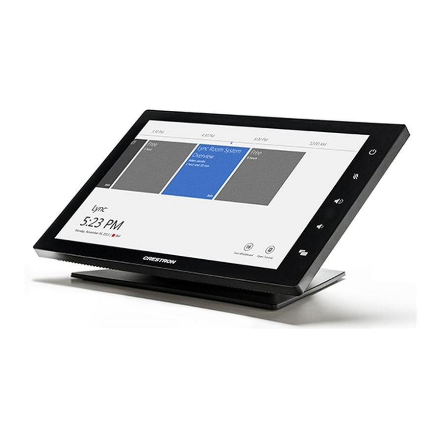
Setting Up the Polycom®
CX8000 for Microsoft® Lync®
The Polycom® CX8000 for Microsoft® Lync® is a comprehensive visual
collaboration solution that is based on Microsoft Lync 2013 software and
market-leading hardware from Crestron
and Polycom for optimized
®
conference room experience. The CX8000 for Microsoft Lync solution
provides full-featured unified communications that include video, voice,
interactive content sharing, presence, and chat from one touch screen
interface.
Two CX8000 systems are o ered. The Polycom CX8000 for Microsoft
Lync Front-of-Room solution, including the Crestron Base Kit, is perfect for
small to medium conference rooms. The Polycom CX8000 for Microsoft
Lync 360 solution, including the Crestron Base Kit and Polycom CX5100
solution, is ideally suited for medium to large sized conference rooms,
executive o ces, and huddle rooms.
For information about the Polycom CX5100, refer to Setting Up the
Polycom CX5100 or CX5500 System.
1 Preparation
A Verify Contents
Before starting installation, check the system package contents.
Included items are listed in the following table. Retain all
documents and parts supplied for use in the installation process.
DESCRIPTION
PART NUMBER
Touch Screen, Color, 10"
TS-1051-C-B-S
Camera, USB, Fixed, 2 Megapixel
CCS-CAM-USB-F-100
Cable, USB 2.0, Series "A" to "B", MALE, 3' (1 m)
CBL-USB-A-B-3
CCS, Cable, Audio, 3.5 mm to (2X) RCA, 3' (1 m)
CBL-AUD-3MM-RCA-3
Cable, VGA to DVI, 30' (~10 m)
CBL-VGA-DVI-30
Cable, HDMI to DVI, 30' (~10 m)
CBL-HD-DVI-30
Cable, HDMI to DVI, 3' (1 m)
CBL-HD-DVI-3
Cable, HDMI to DVI, 20' (~6 m)
CBL-HD-DVI-20
Cable, CAT6, 14' (~4.3 m)
CBL-CAT6-14
CCS, Cable, Sleeve, Expandable, Wrap, 1/2" x 33"
CBL-SLEEVE-EXPAND-WRAP
(13 x 838 mm) L, Blk
1/2-33-B
Crestron Collab Sys, Unified Comm, Codec, MSLYNC
CCS-UC-CODEC-100
Crestron Collab Sys, SPK, Sound Bar, Blk
CCS-SPK-SB-100-B
Wall Mount Kit: CCS-TS-6500
CCS-TS-6500-WMK
3 Cable Assembly
CBL-HD-ASSY
Accessory Bracket Assembly
CSA-BRKT-100-0-ASSY
Codec Mounting Bracket, Right
N/A
Codec Mounting Bracket, Left
N/A
Sound Bar Bracket
N/A
Camera Bracket
N/A
Cable Tray
N/A
Shelf Mount Bracket
Included with codec
Rack Mount Bracket
Included with codec
Power Pack For Ethernet
PWE-480SU
1' (~0.3 m) LAN Cable
CBL-CAT6-1
Cable, USB 2.0, Series "A" to "B", MALE, 10' (1 m)
CBL-USB-A-B-10
*
Mounting hardware included
B Tools Required
Installation requires the use of a #1 or #2 Phillips screwdriver as well as
a socket wrench with 1/2" and 7/16" sockets.
2 Installation
Mounting hardware is packaged with the parts and assemblies to be
attached.
Typical CCS-UC-100-0 installation procedures are provided in steps A
through H. For detailed information about the CCS-TS-6500 Tilting Wall
Mount for 65" Display, refer to the included CCS-TS-6500-WMK
Installation Guide (Doc. 7511). Alternate mounting procedures for the
CCS-UC-CODEC-100 are provided in step H.
A Install Accessory Bracket Assembly
1 Use
the supplied 1/4-20 x 1/2" mounting screws to attach the
accessory bracket assembly to the wall plate (part of the
CCS-TS-6500 Wall Mount Kit).
Wall Plate
QTY
1
1
1
1
1
1
Mounting
1
Screws
1
1
2
1*
1*
1*
1
1*
1*
1*
1*
1*
1*
1
2 If necessary, a power supply for a customer-provided monitor can be
2
1
attached to the accessory bracket in the area indicated in the
1
illustration above, using the two plastic tie wraps (supplied).
1
B Install Mounting Brackets on Codec
1
2 Attach right and left codec mounting brackets to codec using the
C Install Cable Tray
Attach the supplied cable tray to the rear of the codec as follows:
Accessory
Bracket
Attach optional
1
power supply.
2 Route the cables right or left toward their intended termination
3 Loosen the two screws indicated in the illustration below
4 Mount the cable tray on the screws, slide the tray to the right to
Remove three side cover bottom screws from each side of the
codec and discard them.
supplied screws.
Side Cover Bottom
Screws
Attach Supplied
Long Screws
to Brackets
Codec Mounting Bracket, Right
(Codec Mounting Bracket,
Left Not Shown)
Screws
(3 Each Side)
Supplied
Attach all interface and power cables to the rear of the codec,
including those that connect to the CCS-TX-201-C and PoE injector
mounted on the accessory bracket assembly. Refer to the
connection details on page 3.
point, and bundle them with plastic tie wraps as necessary.
approximately 1/4" (6 mm).
engage the keyhole slots, and tighten the screws.
(Codec Mounting
Brackets Not Shown)
Cable Tray
.
Mounting
Screws
1
Advertisement

Related Manuals for Polycom CX8000


Summary of Contents for Polycom CX8000
- Page 1 2 Installation supplied screws. interface. Two CX8000 systems are o ered. The Polycom CX8000 for Microsoft Mounting hardware is packaged with the parts and assemblies to be Lync Front-of-Room solution, including the Crestron Base Kit, is perfect for Side Cover Bottom attached.
- Page 2 Installation (Continued) I Alternate Codec Mounting F Attach Display to the Wall Plate D Attach Codec to the Wall Plate The following information applies only to installations in which the At least two qualified people should perform the mounting codec is not to be attached to a wall plate. procedure.
- Page 3 Display touch monitor cables (E & L) to the keyboard/mouse USB 2.0 ports. Input Power When using the Polycom CX5100 as the video device, select the CX5100 as the audio input device in the CX8000 control panel. HID IN HDMI IN...
- Page 4 © 2014, Polycom, Inc. All rights reserved. Polycom® and the names and marks associated with Polycom’s products are trademarks and/or service marks of Polycom, Inc., and are registered and/or common law marks in the United States and various other countries.