Table of Contents
Advertisement
Owner & Installation Manual
LCD Control Series
Touch Control Series
LCD Control Series
ACYSTAT110AA (Wired, Cooling only)
ACYSTAT120AA (Wireless, Cooling only)
ACYSTAT210AA (Wired, Cooling & Heating)
ACYSTAT220AA (Wireless, Cooling & Heating)
Touch Control Series
ACYSTAT160AA (Wired, Cooling only)
ACYSTAT170AA (Wireless, Cooling only)
ACYSTAT260AA (Wired, Cooling & Heating)
ACYSTAT270AA (Wireless, Cooling & Heating)
August 2010
LCD Chilled Water Control
ACYSTAT410AA
ACYSTAT420AA
Touch Chilled Water Control
ACYSTAT460AA
ACYSTAT470AA
ACYSTAT-IOM-EN
Advertisement
Table of Contents

Related Manuals for Trane LCD Control Series


Summary of Contents for Trane LCD Control Series
- Page 1 Owner & Installation Manual LCD Control Series Touch Control Series LCD Control Series LCD Chilled Water Control ACYSTAT110AA (Wired, Cooling only) ACYSTAT410AA ACYSTAT120AA (Wireless, Cooling only) ACYSTAT420AA ACYSTAT210AA (Wired, Cooling & Heating) ACYSTAT220AA (Wireless, Cooling & Heating) Touch Control Series...
-
Page 2: General System Appearance
Gerneral System Appearance ACYSTAT-IOM-EN... -
Page 3: Table Of Contents
Contents General System Appearance General Information Wireless Remote Control Display Unit and Receiver Board LCD Control series Touch Wired Control Handheld Remote Control Installation Remote Control Installation Electrical Installation Wiring Diagram Outline Dimention ACYSTAT-IOM-EN... -
Page 4: General Information
Cautions are provided at appropriate places in this About The Unit manual to indicate to installers, operators, and service The Trane ACYSTAT is typically used with room air personnel of potentially hazardous situations which, if conditioning systems using concealed type indoor units. - Page 5 The warranty is void if the equipment is modified nor do they provide for every possible contingency to or repaired without the written approval of The Trane be met. Should further information be desired or should Company, if the operating limits are exceeded or if the particular problems arise which are not covered sufficiently control system or the electrical wiring is modified.
-
Page 6: Wireless Remote Control
Wireless Remote Control There are four major components of the Wireless Remote Control system as follows: (1) Control Box Assembly (2) Display Unit and Receiver Board (LCD or Touch wired control) (3) Hand Held Remote Controller (4) Cable (standard assembly length 4 meters) Components (1) and (4), along with the system fan coil or air handler are concealed in the building structure and... -
Page 7: Display Unit And Receiver Board
Display Unit and Receiver Board LCD Wired Control LCD Wired Control Indicators on LCD Wired Control Name and function of buttons 1. Infrared Signal Receiver Receives the signal from handheld remote control and transmits the signal to indoor unit. 2. POWER Button Press this button to start unit operation. - Page 8 Display Unit and Receiver Board LCD Wired Control Operation Mode FAN Mode Press MODE button to select the operation mode. will be shown on the display when FAN mode is Auto --> Low --> Medium --> High selected. Note: Press FAN SPEED button to select the desired fan speed •...
- Page 9 Display Unit and Receiver Board LCD Wired Control Note: To cancel ON TIMER, select ON TIMER setting and • In AUTO mode, the system will automatically switch press MENU button again. between COOL mode and HEAT mode to maintain Note: equally room temperature and set temperature.
- Page 10 Display Unit and Receiver Board LCD Wired Control TURBO Mode TURBO mode rapidly maximizes the cooling capacity in COOL or DRY mode. With this simply mode, the user can easily get the maximum cooling capacity and comfort. Press MENU button and select TURBO mode setting by pressing either The air-conditioner will accelerate capacity up totally 20 minutes or until room temperature is lower than 18...
- Page 11 Display Unit and Receiver Board LCD Wired Control System Features ECONO Mode ECONO mode drastically saves energy with high 1. Watchdog efficient cooling capacity in COOL mode by reducing power consumption. With this simply mode, the user can easily There is a circuit in the system to watch the operation of the microprocessor.
-
Page 12: Touch Wired Control
Display Unit and Receiver Board Touch Wired Control Touch Wired Control 6.2 Operation Mode - Displays the current operation mode: FAN, COOL, Name and function of buttons or DRY in cooling only system; FAN, COOL, DRY, HEAT, or AUTO in cooling and heating systems 1. - Page 13 Display Unit and Receiver Board Touch Wired Control Timer Operation Touch FAN SPEED button to select the desired fan (Available when using with remote speed level and the display will show Low (L), Medium control) (M), High (H), and Auto ( ) respectively.
- Page 14 Display Unit and Receiver Board Touch Wired Control Note: After one and half hour operation of SLEEP mode, • The status display will not show fan speed and set the unit will automatically reduce set temperature temperature. by 0.5 C again. •...
- Page 15 Display Unit and Receiver Board Touch Wired Control System Features Note: • ECONO mode operates only in COOL mode and 1. Watchdog automatically operates when air-conditioner is closed without exiting or canceling ECONO mode. There is a circuit in the system to watch the operation •...
-
Page 16: Handheld Remote Control
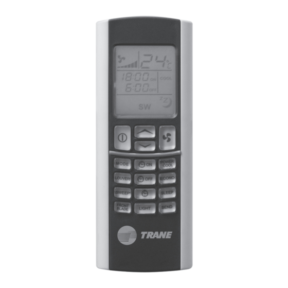
Handheld Remote Control Infrared Remote Control 14. ECONO Button Press this button to save energy. Name and function of buttons 15. SLEEP Button Press this button to control temperature while sleeping 1. Infrared Signal Transmitter and press this button again to cancel. Transmits the signal to indoor unit. - Page 17 Handheld Remote Control Installation of Batteries Indicators on Infrared Remote Control 1. Slide the back cover of the remote control down to take it off. 2. Insert two dry batteries into the slot. Be sure that the + and - directions are correct. 3.
- Page 18 Handheld Remote Control Operation Mode FAN Mode Press Mode button to select the operation mode. “FAN” will be shown on the display when FAN mode Auto --> Low --> Medium --> High is selected. Note: Press FAN SPEED button to select the desired fan •...
- Page 19 Handheld Remote Control Note: Note: • In AUTO mode, the system will automatically switch • The user can confirm ON TIMER during ON TIMER between COOL mode and HEAT mode to maintain setting process by pressing SEND button. equally room temperature and set temperature. •...
- Page 20 Handheld Remote Control Note: • In case of power failure or changing operation mode, • The user can confirm OFF TIMER during OFF TIMER POWERCOOL mode will be automatically cancelled. setting process by pressing SEND button. SLEEP Mode • If there are no other buttons pressed within 15 seconds, OFF TIMER will be cancelled, and the LCD display will SLEEP mode automatically and gradually adjusts room return to show clock.
- Page 21 Handheld Remote Control DIM Function (If available) Note: • Set temperature shown on the display still show the DIM function offers you to dim or restore the brightness of setting without 1 C added/reduced but it will plus/ the wired control display. minus 1 C in the memory.
-
Page 22: Installation
Installation Power Supply - 220 VAC 1 Phase 50/60 Hz 1. The Control Box must not be located more than 2 meters from the location for mounting of the return ACYSTAT can be applied for MCD512-060 air sensor. Please ensure that return air sensor cable is sufficiently long. - Page 23 Installation Locating the Freeze Sensor Locating the Temperature Sensor Locate the return air sensor directly in the air returning to the fan coil or air handler. It should be located so as not to interfere with inspection or removal of return air filters or servicing and repair fan coil or air handler.
-
Page 24: Remote Control Installation
Remote Control Installation Remote Control Installation Location Both of display unit and receiver can be installed within the maximum length cable of 15 meters. The display unit and receiver should be located on the wall approximately 150 clearly visible from most locations in the conditioning space. -
Page 25: Electrical Installation
Electrical Installation All wiring and grounding must comply with local electrical codes. Disconnect both indoor and outdoor power supplies before servicing. Remove the cover of control box to access the terminal block. Connect the wire terminal to the terminal block. (Connection indicated on system wiring diagram). -
Page 26: Wiring Diagram
Wiring diagram ACYSTAT-IOM-EN... - Page 27 Wiring diagram ACYSTAT-IOM-EN...
- Page 28 Wiring diagram ACYSTAT-IOM-EN...
- Page 29 Wiring diagram ACYSTAT-IOM-EN...
-
Page 30: Outline Dimention
Outline Dimension LCD Wired Control ACYSTAT-IOM-EN... - Page 31 Outline Dimension Touch Wired Control ACYSTAT-IOM-EN...
- Page 32 Outline Dimension Handheld Remote Control ACYSTAT-IOM-EN...
- Page 33 Note ACYSTAT-IOM-EN...
- Page 34 ·¢«ß¡— ° °– — π ‡¢µ√“™‡∑«’ °√ÿ ß ‡∑æœ 10400 Stocking Location: Bangkok,Thailand Trane www.trane.com For more information, contact your local Trane has a policy of continuous product and product data improvement and reserves the right to change district office design and specifications without notice.