Table of Contents
Advertisement
Quick Links
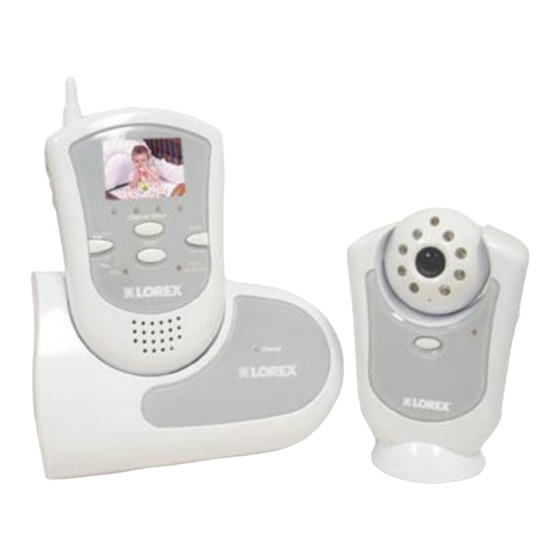
PORTABLE HOME VIDEO
SECURITY SYSTEM
2.4 GHz 1.8" Color TFT LCD Monitor
With Wireless Camera
SG5550
This product broadcasts over public airwaves and its
video and audio signals may be intercepted without
your consent.
FOR MORE INFORMATION
Before operating the system, please read this manual
thoroughly and retain it for future reference.
Advertisement
Table of Contents

Related Manuals for Lorex SG5550


Summary of Contents for Lorex SG5550
- Page 1 PORTABLE HOME VIDEO SECURITY SYSTEM 2.4 GHz 1.8” Color TFT LCD Monitor With Wireless Camera SG5550 This product broadcasts over public airwaves and its video and audio signals may be intercepted without your consent. FOR MORE INFORMATION Before operating the system, please read this manual...
- Page 2 CAUTION RISK OF ELECTRIC SHOCK. DO NOT OPEN CAUTION: TO REDUCE THE RISK OF ELECTRIC SHOCK, DO NOT REMOVE COVER (OR BACK). NO USER-SERVICEABLE PARTS INSIDE. REFER SERVICING TO QUALIFIED SERVICE PERSONNEL. Explanation of two Symbols The lightning flash with arrowhead symbol, within an equilateral triangle, is intended to alert the user to the presence of uninsulated "dangerous voltage“...
- Page 3 SAFETY INSTRUCTIONS IMPORTANT SAFEGUARDS All the safety and operating instructions should be read before the appliance is operated and retained for future reference. 1. HEED WARNINGS - All warnings on the appliance and in the operating instructions should be adhered to. 2.
-
Page 4: Table Of Contents
TABLE OF CONTENTS PAGE INTRODUCTION & FEATURES……………………………………… SYSTEM INCLUDES………………………………………………….. CONTROLS AND FUNCTIONS Monitor Controls – Front Panel ...….……………………..……... Monitor Controls – Side Panels .....……….…..…… Camera Controls ………………………………………………….. Docking Station Controls …………………………………………. INSTALLATION Camera ............……………….…..Monitor ..............………..SYSTEM OPERATION Additional camera connection……………………………………. Alarm Alert …………………………………………………………... - Page 5 • Flexible – move camera & monitor from room to room • Listen-in audio • Auto scanning – up to four cameras • Camera and monitor with AC or battery option • Compatible with all Lorex 2.4 GHz wireless devices • Connect up to four cameras (additional cameras sold separately)
-
Page 6: System Includes
SYSTEM INCLUDES: 1.8” LCD screen – 2.4 GHz Color Wireless Camera with 8 Infra-red emitters 2.4 GHz Color Monitor Docking Station / Charger for Monitor Also includes: 1 – 6V DC 300mA Adapter (Camera) with battery option (4 “AA”, not included) 1 –... -
Page 7: Monitor Controls - Front Panel
MONITOR CONTROLS – FRONT PANEL 1. 2.4GHz Antenna - High gain dipole antenna receives audio and video signal from the camera. 2. LCD - 1.8” Color Screen. 3. Channel Indicator - Shows which Channel the monitor is set to (1-4). Channel 1 is represented on the left side - Channel 4 on the right side. -
Page 8: Monitor Controls - Side Panels
MONITOR CONTROLS – SIDE PANELS 1. Audio Sensitivity - Sets the sensitivity level for the alarm Audio triggering (refer to page 10 for more information). 2. ON/OFF Switch - Switches the power on the monitor ON or OFF. 3. DC Input Jack - Connect to the supplied 6V DC 800 mA AC adapter. Note: If Power is connected via the Docking Station, this input is not required as the monitor will draw Power from the Docking Station. -
Page 9: Camera Controls
CAMERA CONTROLS 1. CDS Sensor - Turns on the IR emitters in low light conditions. 2. Infrared LED’s - Enhance the picture quality in low light conditions. 3. Lens - Color CMOS Image Sensor. 4. Microphone - Built-in condenser microphone provides listen-in audio capability from camera to monitor. -
Page 10: Docking Station Controls
DOCKING STATION CONTROLS 1. Cradle - Carefully slide the monitor downward into the docking cradle. The monitor now has the added feature of Audio / Video Out for connection to a larger monitor (such as a TV) or a VCR. 2. - Page 11 CAMERA INSTALLATION NOTE Ensure the power switch on the monitor and camera are set to the OFF position before proceeding with the following steps. OPTION #1 OPTION #2 WALL DESK Option 1: You can place the camera on a desk or any leveled surface. Select a location that is near an AC outlet and within reach of the AC adapter cord.
- Page 12 MONITOR INSTALLATION Note: Connection of the Monitor to 6V DC 800 mA AC Adapter the Docking Station is optional. The benefits of the Docking Station are: A/V Out and Battery Charging. If using the Docking Station, connect the supplied 6V DC 800 mA adapter to the DC INPUT JACK at the rear of the Docking Station and plug it into an electrical outlet.
-
Page 13: Camera
OPERATION Camera (1) Connect the power adapter to the camera power input and turn on the camera by pressing Power. Ensure the camera is set to channel 1. Monitor (1) Connect the supplied power adaptor to the power input of the monitor or the Docking Station. -
Page 14: Alarm Alert
ALARM ALERT This video security system is equipped with an Audio-based Alarm system, which alerts you of sound at the camera. To activate the Alarm feature, hold the Alarm button on the monitor for 2 seconds. A red light will illuminate to indicate that Alarm mode is active, and the monitor will go to Standby mode (video will not appear on the LCD screen, and the speaker sound will cease). -
Page 15: Auto Scanning
AUTO SCANNING This video security system provides you with the option to automatically switch between the four camera locations. If you have fewer than four cameras, you can also set the system to scan between three or two locations. Setting Auto Scan to 2 or 3 camera locations: 1. -
Page 16: Connecting The Monitor To A Vcr
CONNECTING THE MONITOR TO A TV In order to view video from the camera on a larger screen than the 1.8” LCD, you can use the Video/Audio output from the Docking Station as shown in the diagram below and view the video on TV. Please note: To view the picture on the TV, you must select an A/V or AUX channel. -
Page 18: Technical Specifications
TECHNICAL SPECIFICATIONS MONITOR Display 1.8” Color LCD Resolution 280 x 220 pixels Viewing Angle 90º (L/R) Camera Capable Up to 4 Wireless transmission Up to 300 feet (open space) Power Source 6V 800 mA Adapter (included) Battery Option 4 “AA” Batteries (not included) CAMERA Image Device Color 1/4”... - Page 19 CARE AND MAINTENANCE: Please follow these instructions to ensure proper care and maintenance of this system. Keep your monitor and camera dry. If it gets wet, wipe it dry immediately. Use and store your unit in normal temperature environment. Extreme temperatures can shorten the life of the electronic devices.