Advertisement
Quick Links
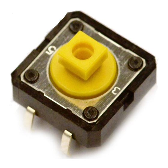
Tactile Switch
A Wide Range of Models:
6 × 6 mm, 12 × 12 mm, Side-operated,
High-force, and Gold-plated.
• Extended mechanical/electrical durability: 10 x 10
operations for 12 x 12 mm type and 1 x 10
operations for the 6 x 6 mm type
• Taped radial type, vertical type and high force
types are available.
• Gold plated models available for increased
contact reliability, resistance to corrosive gas and
insulation failure prevention for ion migration in
harsh environments
• Type B32 Key Tops are available for projected
plunger models.
RoHS Compliant
List of Models
■
6 × 6 mm Models
Type
Plunger
Standard
Flat type
(B3F-1000)
Projected type
6
6
Height
Operating force
(OF)
4.3 mm
0.98 N {100 gf}
1.47 N {150 gf}
2.55 N {260 gf}
4.9 N {500 gf}
5.0 mm
0.98 N {100 gf}
1.47 N {150 gf}
2.55 N {260 gf}
4.9 N {500 gf}
5.0 mm
0.98 N {100 gf}
(7.5-mm pitch)
7.0 mm
0.98 N {100 gf}
1.47 N {150 gf}
9.5 mm
0.98 N {100 gf}
1.47 N {150 gf}
2.55 N {260 gf}
7.3 mm
0.98 N {100 gf}
1.47 N {150 gf}
2.55 N {260 gf}
4.9 N {500 gf}
Plunger color
Bags (in units of 100 Switches)
Without ground
terminal
lvory
B3F-1000
Yellow
B3F-1002
Orange
B3F-1005
Red
B3F-1006
Black
B3F-1020
Gray
B3F-1022
Pink
B3F-1025
Blue
B3F-1026
Black
---
Black
B3F-1060
Yellow
B3F-1062
Black
B3F-1070
Yellow
B3F-1072
Orange
B3F-1075
lvory
B3F-1050
Yellow
B3F-1052
Orange
B3F-1055
Red
B3F-1056
B3F
With ground
terminal
B3F-1100
B3F-1102
B3F-1105
---
B3F-1120
B3F-1122
B3F-1125
---
B3F-1110
---
---
---
---
---
B3F-1150
B3F-1152
B3F-1155
---
1
Advertisement

Related Manuals for Omron B3F


Summary of Contents for Omron B3F
- Page 1 Tactile Switch A Wide Range of Models: 6 × 6 mm, 12 × 12 mm, Side-operated, High-force, and Gold-plated. • Extended mechanical/electrical durability: 10 x 10 operations for 12 x 12 mm type and 1 x 10 operations for the 6 x 6 mm type •...
- Page 2 Type Plunger Height Operating force Plunger color Bags (in units of 100 Switches) (OF) Without ground With ground terminal terminal Side-operated 3.15 mm 0.98 N {100 gf} lvory B3F-3100 Flat type (B3F-3000) 1.47 N {150 gf} Yellow B3F-3102 2.55 N {260 gf} Orange B3F-3105 3.85 mm...
-
Page 3: Operating Characteristics
Ratings/Characteristics ■ 1 to 50 mA, 5 to 24 VDC (resistive load) (B3F-G: 100 μA to 50 mA, 5 to 24 VDC) Ratings Ambient operating temperature -25°C to +70°C at 60%RH max. (with no icing or condensation) Ambient operating humidity 35% to 85% (at +5 to +35°C) Contact form SPST-NO... - Page 4 The numbers used for terminals in the following graphics are indicated in the “Bottom View” diagram below. In this diagram, the Switch is rotated so that the terminals are on the right and left-hand sides, and the OMRON logo ap- pears the right way up.
- Page 5 Standard, Projected Plunger Type Standard, Flat Plunger Type (without Ground Terminal) (without Ground Terminal) B3F-1070, B3F-1072, B3F-1075, B3F-1072-G B3F-1050, B3F-1052 B3F-1055, B3F-1056 B3F-1052-G PCB Mounting (Top View) PCB Mounting (Top View) (Single-sided PCB, t=1.6) (Single-sided PCB, t=1.6) ±0.2 ±0.2 ±0.2 ±0.2 ±0.2 ±0.2...
- Page 6 12 × 12 mm Models Standard, Long-durability, Standard, Long-durability, and High-reliability Models and High-reliability Models Flat Plunger Type Flat Plunger Type (without Ground Terminal) (with Ground Terminal) B3F-4100, B3F-4105, B3F-4000, B3F-4005, B3F-5100, B3F-5101 B3F-5000, B3F-5001 PCB Mounting (Top View) PCB Mounting (Top View) (Single-sided PCB, t=1.6) (Single-sided PCB, t=1.6) Two, 1.8...
- Page 7 The numbers used for terminals in the following graphics are indicated in the “Bottom View” diagram below. In this diagram, the Switch is rotated so that the terminals are on the right and left-hand sides, and the OMRON logo appears the right way up.
- Page 8 Flat Plunger Type ±0.3 (with Ground Terminal) B3F-6120, B3F-6122 12.7 ±1 ±0.3 6.35 ±1 2 max. 3.5 dia. 0.5 max. Support (1.1) 0.5 max. tape ±0.5 0.2 max. ±0.5 ±0.2 +0.8 −0.5 −0.2 dia. ±0.2 Terminal Arrangement PCB Mounting /Internal Connections (Top View) 12.7 Carrier tape...
- Page 9 • Application examples provided in this document are for reference only. In actual applications, confirm equipment functions and safety before using the product. • Consult your OMRON representative before using the product under conditions which are not described in the manual or applying the product to nuclear control systems, railroad systems, aviation systems, vehicles, combustion systems, medical equipment, amusement machines, safety equipment, and other systems or equipment that may have a serious influence on lives and property if used improperly.