Endress+Hauser Levelflex M FMP40 Operating Instructions Manual
Run time measurement
Hide thumbs
Also See for Levelflex M FMP40:
- Operating instructions manual (128 pages) ,
- Function manual (84 pages) ,
- Technical information (72 pages)

Related Manuals for Endress+Hauser Levelflex M FMP40


Summary of Contents for Endress+Hauser Levelflex M FMP40
- Page 1 Operating Instructions Levelflex M FMP40 Run Time Measurement BA242F/00/en/03.09 No. 71074787 Valid as of software version: 01.04.zz...
- Page 2 Commissioning via Endress+Hauser operating programm In the "Commissioning" section, you learn how to switch on the device and check the functioning. Additional information on the operation via the Endress+Hauser operating program(FieldCare) can be found in Operating Instructions BA027S/04. Æ → ä 84 Fault Tracking / Trouble Shooting If faults occur during operation, use the checklist to localise the cause.
- Page 3 Levelflex M FMP40 with HART/4...20 mA Brief overview Brief operating instructions Levelflex M - Brief operating instructions KA189F/00/a2/03.07 52012501 Contrast: measured value dist./ meas value Group selection basic setup tank medium process empty full dist./ check range of start properties property cond.
- Page 4 Brief overview Levelflex M FMP40 with HART/4...20 mA Endress + Hauser...
-
Page 5: Table Of Contents
Quick wiring guide ......36 Contact addresses of Endress+Hauser ... 91 Connecting the measuring unit . -
Page 6: Safety Instructions
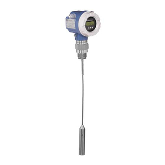
Levelflex M FMP40 with HART/4...20 mA Safety instructions Designated use The Levelflex M FMP40 is a compact level transmitter for the continuous measurement of solids and liquids, measuring prinziple: Guided Level Radar / TDR: Time Domain Reflectometry. Installation, commissioning and operation The Levelflex M has been designed to operate safely in accordance with current technical, safety and EU standards. -
Page 7: Notes On Safety Conventions And Symbols
Levelflex M FMP40 with HART/4...20 mA Safety instructions Notes on safety conventions and symbols In order to highlight safety-relevant or alternative operating procedures in the manual, the following conventions have been used, each indicated by a corresponding symbol in the margin. -
Page 8: Identification
Dat./Insp.: D01301-A Reference to additional safety-relevant documentation L00-FMP4xxxx-18-00-00-en-001 Fig. 1: Information on the nameplate of the Levelflex M FMP40 (example) 2.1.2 Ordering structure This overview does not mark options which are mutually exclusive. Approval: A Non-hazardous area Non-hazardous area, WHG... - Page 9 Levelflex M FMP40 with HART/4...20 mA Identification Probe: A Rope 4mm / 1/6", mainly liquid Rope 6mm / 1/4", solid H Rope 6mm / 1/4", PA > steel, solid, T = 100°C / 212°F Rod 6mm, liquid Rod 12mm, liquid...
- Page 10 Identification Levelflex M FMP40 with HART/4...20 mA Process Connection: DN100 PN25/40, AlloyC22 >316L flange EN1092-1 (DIN2527) DN150 PN10/16 B1, 316L flange EN1092-1 (DIN2527 C) DN150 PN10/16, AlloyC22 >316L flange EN1092-1 (DIN2527) DN200 PN16 B1, 316L flange EN1092-1 (DIN2527 C) Thread ISO228 G3/4, 316L...
- Page 11 Levelflex M FMP40 with HART/4...20 mA Identification Housing; Cable Entry: T12 Alu, coated IP68; plug 7/8" + OVP F23 316L IP68; gland M20 F23 316L IP68; thread G1/2 F23 316L IP68; thread NPT1/2 F23 316L IP66; plug M12 F23 316L IP68; plug 7/8"...
-
Page 12: Scope Of Delivery
The device complies with the applicable standards and regulations as listed in the EC declaration of conformity and thus complies with the statutory requirements of the EG directives. Endress+Hauser confirms the successful testing of the device by affixing to it the CE mark. -
Page 13: Mounting
Levelflex M FMP40 with HART/4...20 mA Mounting Mounting Quick installation guide Mounting with threaded boss F12/F23 or T12 housing The housing can be turned 350° in order to simplify access to the display and the terminal compartment 1½" F12/F23 housing... -
Page 14: Incoming Acceptance, Transport, Storage
Mounting Levelflex M FMP40 with HART/4...20 mA Incoming acceptance, transport, storage 3.2.1 Incoming acceptance Check the packing and contents for any signs of damage. Check the shipment, make sure nothing is missing and that the scope of supply matches your order. -
Page 15: Installation Conditions
Levelflex M FMP40 with HART/4...20 mA Mounting Installation conditions 3.3.1 Dimensions Housing dimensions Dimensions for the process connection and the probe type → ä 16. max. 110 ENDRESS+HAUSER F12 housing (Aluminium) L00-F12xxxx-06-00-00-en-001 max. 100 ENDRESS+HAUSER T12 housing (Aluminium) L00-T12xxxx-06-00-00-en-001 max. 94... - Page 16 Mounting Levelflex M FMP40 with HART/4...20 mA Levelflex M FMP40 - process connection, probe type Housing dimensions → ä 15 F12 / T12 / F23 housing Variant “2”: Variant “3”: Separator remote electronic 4 x Ø 8.5 Ø 60.3 Variant “4”: remote electronic Ø...
-
Page 17: Installation
Levelflex M FMP40 with HART/4...20 mA Mounting Installation 3.4.1 Mounting kit In addition to the tool needed for flange mounting, you will require the following tool: • For the mounting of threaded connection: 60 mm Open-end spanner for 1½", 50 mm Open-end spanner for ¾". - Page 18 Mounting Levelflex M FMP40 with HART/4...20 mA 3.4.3 Mounting probes in an empty silo " Caution! If there is a risk of electrostatic discharge from the product, then both processconnection and rope must be earthed before the probe is lowered into the silo.
- Page 19 Levelflex M FMP40 with HART/4...20 mA Mounting 3.4.4 Mounting rope probes in a partially full silo It is not always possible to empty a silo which is already in operation. Because the probe can be turned in the threaded boss, it can also be mounted when the silo is only partially filled. In order to...
- Page 20 Mounting Levelflex M FMP40 with HART/4...20 mA 3.4.5 Engineering hints for level measurement in bulk solids and fluids • Normally, rope probes should be used for bulk solids, rod probes are only suitable for short measuring ranges up to approx. 2 m in bulk solids. This applies above all to applications in which the probe is installed laterally at an angle and for light and pourable bulk solids.
- Page 21 Levelflex M FMP40 with HART/4...20 mA Mounting Other installations • Select the mounting location such that the distance to internals (5) (e.g. limit switch, struts) > is 300 mm over the entire length of the probe, also during operation. • Probe must within the measuring span not touch any internals during operation.
- Page 22 Mounting Levelflex M FMP40 with HART/4...20 mA Type of probe installation • Probes are mounted to the process connection with threaded connections or flanges and are usually also secured with these. If during this installation there is the danger that the probe end moves so much that it touches the tank floor or cone at times, the probe must, if necessary, be shortened and fixed down.
- Page 23 Levelflex M FMP40 with HART/4...20 mA Mounting Supporting probes against warping For WHG or Ex approval: For probe lengths ≥ 3 m a support is required (see figure). For GL/ABS approval: Rod probes ∅ 16 mm ≤ 1 m permissible, Rod probes ∅ 6 mm not permissible.
- Page 24 Mounting Levelflex M FMP40 with HART/4...20 mA 3.4.6 Special notes for bulk solids • In the case of bulk solids, as great a distance as possible from the filling curtain is especially important to avoid wear. • In concrete silos, a large distance (B) should be observed between the probe and the concrete wall, if possible >= 1m, but at least...
- Page 25 Levelflex M FMP40 with HART/4...20 mA Mounting 3.4.7 Installation in bulk solid silos Tensile load Bulk solids exert tensile forces on rope probes whose height increases with: • the length of the probe, i.e. max. cover, • the bulk density of the product, •...
- Page 26 Mounting Levelflex M FMP40 with HART/4...20 mA Since the tensile forces are also heavily dependent on the viscosity of the product, a higher safety factor is necessary for highly viscous products and if there is a risk of cornice build-up.
- Page 27 Levelflex M FMP40 with HART/4...20 mA Mounting Installation in underground tanks • Use coax probe for nozzles with large diameters in order to avoid reflections at the nozzle wall. L00-FMP4xxxx-17-00-00-yy-022 Measurement in corrosive fluids For measurement in corrosive liquids use Levelflex M FMP41C. When using plastic tanks it is also possible to mount the probe on the outside of the tank (see Installation instructions on →...
- Page 28 Mounting Levelflex M FMP40 with HART/4...20 mA Mounting Location • Recommended distance B wall-mounted rope probe: ~1/6...1/4 of the container diameter (min. 100 mm/4", concrete silos: min. 500 mm). • Not central (2) in metallic tanks. • Not in the filling curtain (3).
- Page 29 Levelflex M FMP40 with HART/4...20 mA Mounting 3.4.9 Notes on special installation situations Welding the probe into the vessel " Caution! Before welding the probe into the vessel, it must be grounded by a low-resistive connection. If this is not possible, the electronics as well as the HF module must be disconnected. Otherwise the electronics may be damaged.
- Page 30 Mounting Levelflex M FMP40 with HART/4...20 mA Installation from the side • If installation from above is not possible, the Levelflex can also be mounted from the side. • In this case, always fix the rope probe (see "Fixing rope probe").
- Page 31 Levelflex M FMP40 with HART/4...20 mA Mounting • It is also possible to mount the probe externally on the tank wall for measuring in Aqueous solutions. Measurement then takes place through the tank wall without contacting the medium. If people are in the vicinity of the probe mounting location, a plastic half pipe with a diameter of approx.
- Page 32 Mounting Levelflex M FMP40 with HART/4...20 mA Installation in ≥ DN 300 nozzles If installation in ≥ 300mm/12" nozzles is unavoidable, installation must be carried out in accordance with the sketch on the right. pipe Ø 150 … 180 lower edge of...
- Page 33 Levelflex M FMP40 with HART/4...20 mA Mounting 3.4.10 Installation for difficult to access process connections For tight spaces or temperatures above that in the graphic, the electronics housing can be ordered with distance pipe or connecting cable (seperate housing). Installation with distance pipe Follow installation instructions on →...
- Page 34 Mounting Levelflex M FMP40 with HART/4...20 mA Installation with remote electronic • Follow installation instructions on → ä 20 • Mount housing on a wall or pipe as shown in the diagram. wall ENDRESS+HAUSER Levelflex M 4 x Ø 8,5...
-
Page 35: Post-Installation Check
Levelflex M FMP40 with HART/4...20 mA Mounting 3.4.11 Turn housing After mounting, the housing can be turned 350° in order to simplify access to the display and the terminal compartment. Proceed as follows to turn the housing to the required position: •... -
Page 36: Wiring
Wiring Levelflex M FMP40 with HART/4...20 mA Wiring Quick wiring guide Wiring in F12/F23 housing " Before connection please note the following: ● The power supply must be identical to the data on the Caution! nameplate (1). ENDRESS+HAUSER Made in Germany... - Page 37 Levelflex M FMP40 with HART/4...20 mA Wiring Wiring in T12 housing " Before connection please note the following: ● The power supply must be identical to the data on the nameplate (1). Caution! ENDRESS+HAUSER Made in Germany LEVELFLEX-M D-79689 Maulburg ●...
-
Page 38: Connecting The Measuring Unit
Wiring Levelflex M FMP40 with HART/4...20 mA Connecting the measuring unit Terminal compartment Three housings are available: • Aluminium housing F12 with additionally sealed terminal compartment for: – standard, – Ex ia. – Dust-Ex • Aluminium housing T12 with separate terminal compartment for: –... - Page 39 Levelflex M FMP40 with HART/4...20 mA Wiring Cable entry Cable gland: M20x1.5 (only cable entry for Ex d) Cable entry: G ½ or ½ NPT Supply voltage HART, 2-wire The following values are the voltages across the terminals directly at the instrument:...
- Page 40 Wiring Levelflex M FMP40 with HART/4...20 mA Overvoltage protection If the measuring device is used for the level measurement in flammable liquids which requires the use of an overvoltage protection according to DIN EN 60079-14, standard for testprocedures DIN IEC 60060-1 (10 kA, Puls 8/20 μs) it has to be ensured that •...
-
Page 41: Recommended Connection
Levelflex M FMP40 with HART/4...20 mA Wiring Recommended connection 4.3.1 Equipotential bonding Connect the Equipotential bonding to the external ground terminal (1) of the transmitter. F12/F23 housing T12 housing L00-FMP4xxxx-17-00-00-en-032 4.3.2 Wiring screened cable " Caution! In Ex applications, the instrument must only be grounded on the sensor side. Further safety instructions are given in the separate documentation for applications in explosion hazardous areas. -
Page 42: Operation
Operation Levelflex M FMP40 with HART/4...20 mA Operation Quick operation guide ENDRESS + HAUSER – >3 s Return to basic setup tank shape medium property Group Selection Standard safety settings aluminium tank lenght adjustment plastic tank bypass / pipe linearisation... - Page 43 Levelflex M FMP40 with HART/4...20 mA Operation 5.1.1 General structure of the operating menu The operating menu is made up of two levels: • Function groups (00, 01, 03, …, 0C, 0D): The individual operating options of the instrument are split up roughly into different function groups.
-
Page 44: Display And Operating Elements
Operation Levelflex M FMP40 with HART/4...20 mA Display and operating elements Four lines with 20 characters each. Display contrast adjustable through key combination. (liquid crystal display) Orde Ser.- Orde Ser.- r Cod r Cod No.: No.: sber sber surin surin... - Page 45 Levelflex M FMP40 with HART/4...20 mA Operation 5.2.2 Display symbols The following table describes the symbols that appear on the liquid crystal display: Sybmol Meaning ALARM_SYMBOL This alarm symbol appears when the instrument is in an alarm state. If the symbol flashes, this indicates a warning.
-
Page 46: Local Operation
Operation Levelflex M FMP40 with HART/4...20 mA Local operation 5.3.1 Locking of the configuration mode The Levelflex can be protected in two ways against unauthorised changing of instrument data, numerical values or factory settings: "unlock parameter" (0A4): A value <> 100 (e.g. 99) must be entered in "unlock parameter" (0A4) in the "diagnostics"... - Page 47 There is no need to change these parameters under normal circumstances and consequently, they are protected by a special code known only to the Endress+Hauser service organization. Please contact Endress+Hauser if you have any questions.
- Page 48 Operation Levelflex M FMP40 with HART/4...20 mA 5.3.3 Factory settings (Reset) " Caution! A reset sets the instrument back to the factory settings. This can lead to an impairment of the measurement. Generally, you should perform a basic setup again following a reset.
-
Page 49: Display And Acknowledging Error Messages
Levelflex M FMP40 with HART/4...20 mA Operation Display and acknowledging error messages Type of error Errors that occur during commissioning or measuring are displayed immediately on the local display. If two or more system or process errors occur, the error with the highest priority is the one shown on the display. - Page 50 The operating program FieldCare is an Endress+Hauser Plant Asset Management Tool based on FDT technology. You can use Field-Care to configure all your Endress+Hauser devices, as well as devices from other manufacturers that support the FDT standard. It is compatible with the following operating systems: Win2000, WinXP and Windows Vista.
- Page 51 Levelflex M FMP40 with HART/4...20 mA Operation Signal analysis via envelope curve L00-FMP4xxxx-20-00-00-en-007 Tank linearization L00-fmp-Ixxx-20-00-00-en-041 Endress + Hauser...
-
Page 52: Hart Communication
Operation Levelflex M FMP40 with HART/4...20 mA HART communication Apart from local operation, you can also parameterise the measuring instrument and view measured values by means of a HART protocol. There are two options available for operation: • Operation via the universal handheld operating unit, the Field Communicator 375. -
Page 53: Commissioning
Levelflex M FMP40 with HART/4...20 mA Commissioning Commissioning Function check Make sure that all final checks have been completed before you start up your measuring point: • Checklist “Post-installation check”. • Checklist “Post-connection check”. Switching on the measuring device When the instrument is switched on for the first time, the following messages appear in a sequence of 5 s on the display: software version, communication protocoll and language selection. -
Page 54: Basic Setup
Commissioning Levelflex M FMP40 with HART/4...20 mA Basic Setup tank shape flange: Standard reference point of measurement measuring cond. Unknown measuring cond. Standard empty calibr. full calibr. mapping E = empty calibr. (= zero) LN = probe length setting in 005... - Page 55 Levelflex M FMP40 with HART/4...20 mA Commissioning The basic setup is sufficient for successful commissioning in most applications. The Levelflex is initially adjusted at the factory to the probe length ordered, so that in most cases only the application parameters, that automatically adapt the device to the measuring conditions, need to be entered.
-
Page 56: Basic Setup With The Vu331
Commissioning Levelflex M FMP40 with HART/4...20 mA Basic Setup with the VU331 Function "measured value" (000) ⇒ ENDRESS + HAUSER – This function displays the current measured value in the selected unit (see "customer unit" (042)) function). The number of digits after decimal point can be selected in the "no.of decimals"... - Page 57 Levelflex M FMP40 with HART/4...20 mA Commissioning bypass / pipe The "bypass / pipe" option is designed especially for the installation of probes in a bypass or a stilling well. If this option is selected, the upper blocking distance is preset to 100 mm.
- Page 58 Commissioning Levelflex M FMP40 with HART/4...20 mA The lower group applies to very loose or loosened bulk solids. Reduction of the max. possible measuring range by means of: • extremely loose surfaces of bulk solids, e.g. bulk solids with low piled density when filled pneumatically.
- Page 59 Levelflex M FMP40 with HART/4...20 mA Commissioning Function "probe length" (031) ⇒ ENDRESS + HAUSER – Use this function to select whether the probe length was changed after factory calibration. Only then is it necessary to enter or correct the probe length.
- Page 60 Commissioning Levelflex M FMP40 with HART/4...20 mA Function "empty calibr." (005) ⇒ ENDRESS + HAUSER – This function is used to enter the distance from the flange (reference point of the measurement) to the minimum level (=zero). E = empty calibration (= zero) L00-FMP4xxxx-14-00-06-en-008 Function "full calibr."...
- Page 61 Levelflex M FMP40 with HART/4...20 mA Commissioning Function "dist./meas.value" (008) ⇒ ENDRESS + HAUSER – The distance measured from the reference point to the product surface and the meas. value calculated with the aid of the empty adjustment are displayed. Check whether the values correspond to the actual meas.
- Page 62 Commissioning Levelflex M FMP40 with HART/4...20 mA distance = ok Use this function at part-covered probe. Choosing function "manual" or "probe free" at free probe. • mapping is carried out up to the currently measured echo • The range to be suppressed is suggested in the "range of mapping" (052) function Anyway, it is wise to carry out a mapping even in this case.
- Page 63 Levelflex M FMP40 with HART/4...20 mA Commissioning Function "dist./meas.value" (008) ⇒ ENDRESS + HAUSER – The distance measured from the reference point to the product surface and the meas. value calculated with the aid of the empty alignment are displayed again. Check whether the values correspond to the actual meas.
-
Page 64: Blocking Distance
Commissioning Levelflex M FMP40 with HART/4...20 mA Blocking distance Function "upper block. dist" (059) ⇒ ENDRESS + HAUSER – For rod probes and for rope probes with lengths of up to 8 m, the upper blocking distance is preset to 0.2 m on delivery. - Page 65 Levelflex M FMP40 with HART/4...20 mA Commissioning Maximum measured error Typical statements for reference conditions: DIN EN 61298-2, percentage of the span. Output: digital analogue sum of non-linearity, measurig range: ± 0.06 % non-repeatability – up to 10 m: ±3 mm and hysteresis –...
-
Page 66: Envelope Curve With Vu331
Commissioning Levelflex M FMP40 with HART/4...20 mA Envelope curve with VU331 After the basic setup, an evaluation of the measurement with the aid of the envelope curve ("envelope curve" (0E)) function group) is recommended.). 6.6.1 Function "plot settings" (0E1) ⇒... -
Page 67: Function "Envelope Curve Display" (0E3)
Levelflex M FMP40 with HART/4...20 mA Commissioning Function "envelope curve display" (0E3) You can obtain the following information from the envelope curve display in this function: quality of evaluated echo full calibr. evaluated echo empty calibr. is marked envelope curve... - Page 68 Commissioning Levelflex M FMP40 with HART/4...20 mA 6.7.3 Mapping • Factory mapping Mapping (empty curve) is already available in the device when the device is delivered. • Customer mapping In a partially filled state, the distance up to 10 cm before the actual total level can be mapped (range of mapping = actual distance from total level - 10 cm), or values >...
- Page 69 Levelflex M FMP40 with HART/4...20 mA Commissioning Move-Modus Then press , to switch to Move mode. Either is displayed. You now have the following options: • shifts the curve to the right. • shifts the curve to the left. L00-FMPxxxxx-07-00-00-xx-002...
-
Page 70: Basic Setup With The Endress+Hauser Operating Program
Commissioning Levelflex M FMP40 with HART/4...20 mA Basic setup with the Endress+Hauser operating program To carry out the basic setup with the operating program, proceed as follows: • Start the operating program and establish a connection. • Select the "basic setup" function group in the navigation window. - Page 71 Levelflex M FMP40 with HART/4...20 mA Commissioning Basic setup step 2/6: • Enter the application parameters (see chapter basic setup with "VU331"): – tank properties – medium properties – process properties l00-fmp4xxxx-20-00-00-en-002 Basic setup step 3/6: • Enter the application parameters (see chapter basic setup with "VU331"): –...
- Page 72 Commissioning Levelflex M FMP40 with HART/4...20 mA Basic setup step 4/6: • Enter the application parameters (see chapter basic setup with "VU331"): – probe length – probe – probe length – determine length l00-fmp4xxxx-20-00-00-en-004 Basic setup step 5/6: • Enter the application parameters (see chapter basic setup with "VU331"): –...
- Page 73 Levelflex M FMP40 with HART/4...20 mA Commissioning Basic setup step 6/6: • Interference echo suppression takes place in this step • The measured distance and the current measured value are always displayed in the header l00-fmp4xxxx-20-00-00-en-006.gif 6.8.1 Signal analysis via envelope curve After the basic setup, it is recommended to evaluate the measurement with the aid of the envelope curve.
- Page 74 Commissioning Levelflex M FMP40 with HART/4...20 mA Evaluating the measurement with the aid of the envelope curve Typical curve shapes: The following examples display typical curve shapes for a rope or rod probe in an empty tank. For all probe types, a negative probe end signal is shown. For rope probes, the end weight causes an additional preliminary positive echo (see rope probe diagram).
- Page 75 Levelflex M FMP40 with HART/4...20 mA Commissioning Evaluating the measurement: • The map must correspond to the course of the envelope curve (for rod probes up to approx. 5 cm and for rope probes up to approx. 25 cm before the end of the probe) when the tank is empty.
-
Page 76: Maintenance
Repairs The Endress+Hauser repair concept assumes that the measuring devices have a modular design and that customers are able to undertake repairs themselves (see Chap. 9.4 "Spare Parts" → ä 89). Please contact Endress+Hauser Service for further information on service and spare parts. -
Page 77: Accessories
Levelflex M FMP40 with HART/4...20 mA Accessories Accessories Various accessories, which can be ordered separately from Endress+Hauser, are available for the Levelflex M. Weather protection cover A Weather protection cover made of stainless steel is recommended for outdoor mounting (order code: 543199-0001). The shipment includes the protective cover and tension clamp. -
Page 78: Remote Display And Operation Fhx40
Accessories Levelflex M FMP40 with HART/4...20 mA Remote display and operation FHX40 Micropilot M Wall-mounting Pipe-mounting Levelflex M (without mounting bracket) (mounting bracket and plate Prosonic M e r . e r . supplied optionally, s. product structure) o . : o . -
Page 79: Centering Disks
Levelflex M FMP40 with HART/4...20 mA Accessories Centering disks If the probes with rod version are used in stilling well or bypass, it must be ensured that the probe does not come into contact with the wall. The centering disk fixes the rod probe in the middle of the pipe. -
Page 80: Commubox Fxa191 Hart
For details refer to TI404F/00/en. Commubox FXA291 The Commubox FXA291 connects Endress+Hauser field instruments with CDI interface (= Endress+Hauser Common Data Interface) to the USB interface of a personal computer or a notebook. For details refer to TI405C/07/en. Note! For the following Endress+Hauser instruments you need the "ToF Adapter FXA291" as an additional accessory: •... -
Page 81: Adapter Flange Fau70E / Fau70A
Levelflex M FMP40 with HART/4...20 mA Accessories Adapter flange FAU70E / FAU70A adapter flange probe nozzle L00-FMP4xxxx-00-00-00-en-001 Process Connection 12 DN50 PN16 A, flange EN1092-1 (DIN2527 B) 14 DN80 PN16 A, flange EN1092-1 (DIN2527 B) 15 DN100 PN16 A, flange EN1092-1 (DIN2527 B) -
Page 82: Extension Rod / Centering
Accessories Levelflex M FMP40 with HART/4...20 mA 8.10 Extension rod / Centering DN 50 (2") DN 80 (3") DN 150 (6") DN 200 (8") DN 250 (10") nozzle For DN200 and DN250 height in combination with horn adapter Keep metal tube... -
Page 83: Isolated Tie Down
Levelflex M FMP40 with HART/4...20 mA Accessories 8.11 Isolated tie down Mounting-kit Order - No. Reliable, isolated mounting for 4mm rope probe 52014249 for 6mm rope probe 52014250 If a rope probe has to be fixed and asecure grounded mounting is not possible, we recommend using the insulating... -
Page 84: Trouble-Shooting
Trouble-shooting Levelflex M FMP40 with HART/4...20 mA Trouble-shooting Trouble-shooting instructions Levelflex M -Trouble Shooting Check voltage and Not ok compare it with the Instrument does Connect the Instrument works? Ready specifications on the not respond correct voltage nameplate. Check the polarity... -
Page 85: System Error Messages
Levelflex M FMP40 with HART/4...20 mA Trouble-shooting System error messages Code Description Possible cause Remedy A102 checksum error device has been powered off before data reset general reset & new calibr. could be stored; avoid emc problem; required emc problem;... - Page 86 Trouble-shooting Levelflex M FMP40 with HART/4...20 mA Code Description Possible cause Remedy W601 linearisation ch1 curve not linearization not monotonously increasing correct linearisation table monotone W611 less than 2 linearisation number of entered linearization points < 2 correct linearisation table...
-
Page 87: Application Errors
Levelflex M FMP40 with HART/4...20 mA Trouble-shooting Application errors Error Output Possible cause Remedy A warning or alarm Depending on the configuration See table of 1. See table of error messages (→ ä 85) has occurred. error messages (→ ä 85) →... - Page 88 Trouble-shooting Levelflex M FMP40 with HART/4...20 mA Device displays a Incorrect probe length 1. Carry out automatic probe length level when the detection when the tank is tank is empty. empty. 20 mA/100% 2. Carry out mapping over entire probe when the tank is empty (probe free!).
-
Page 89: Spare Parts
Levelflex M FMP40 with HART/4...20 mA Trouble-shooting Spare Parts An overview of the spare parts for your device is available in the internet at www.endress.com. To obtain information on the spare parts, proceed as follows: Go to "www.endress.com" and select your country. -
Page 90: Return
Levelflex M FMP40 with HART/4...20 mA Return The following procedures must be carried out before a transmitter is sent to Endress+Hauser e.g. for repair or calibration: • Remove all residue which may be present. Pay special attention to the gasket grooves and crevices where fluid may be present. -
Page 91: Software History
• Operating menu extended BA245F/00/en/06.06 52011936 BA242F/00/en/11.06 52011930 BA242F/00/en/03.09 71074787 Contact addresses of Endress+Hauser Contact addresses can be found on our homepage: www.endress.com/worldwide. If you have any questions, please do not hesitate to contact your Endress+Hauser representative. Endress + Hauser... -
Page 92: Technical Data
Technical data Levelflex M FMP40 with HART/4...20 mA Technical data 10.1 Additional technical data 10.1.1 Input The measured variable is the distance between a reference point (see Fig. on → ä 16) and the Measured variable product surface. Subject to the input empty distance (E, see Fig. on → ä 104), the level is calculated. - Page 93 Levelflex M FMP40 with HART/4...20 mA Technical data 10.1.3 Performance characteristics Reference operating • Temperature = +20 °C (68 °F) ±5 °C (9 °F) conditions • Pressure = 1013 mbar abs. (14.7 psia) ±20 mbar (0.3 psi) • Humidity = 65 % ±20% •...
- Page 94 Technical data Levelflex M FMP40 with HART/4...20 mA 10.1.4 Operating conditions: Environment Ambient temperature range Ambient temperature for the transmitter: -40 °C ... +80 °C (-40 °F … +176 °F) The functionality of the LCD display may be limited for temperatures Ta<-20 °C and Ta>+60 °C.
- Page 95 Levelflex M FMP40 with HART/4...20 mA Technical data 10.1.5 Operating conditions: Process Process temperature range The maximum permitted temperature at the process connection (see Figure for measuring point) is determined by the O-ring version ordered: O-ring-material min. Temperature max. Temperature FKM (Viton) -30 °C/-22 °F...
- Page 96 All Probes with ¾"- connection Lower edge of the process connections: PPS-GF 40 Endress+Hauser supplies DIN/EN flanges made of stainless steel AISI 316L with the material number 1.4435 or 1.4404. With regard to their stability-temperature property, the materials 1.4435 and 1.4404 are grouped together under 13EO in EN 1092-1 Tab.
- Page 97 Levelflex M FMP40 with HART/4...20 mA Technical data 10.1.6 Mechanical construction Tolerance of probe length Rod probes over 1 m / 3.2 ft 3 m / 9.8 ft 6 m / 20 ft up to 1 m / 3.2 ft 3 m / 9.8 ft...
- Page 98 The measuring system meets the legal requirements of the applicable EC guidelines. These are listed in the corresponding EC Declaration of Conformity together with the standards applied. Endress+Hauser confirms successful testing of the device by affixing to it the CE mark. WHG. See "Ordering structure" on → ä 8 - (see ZE 256F/de).
- Page 99 Levelflex M FMP40 with HART/4...20 mA Technical data Ex approval Correlation of safety instructions (XA) and certificates (ZE) to the instrument: Feature Non-hazardous area NEPSI Ex em(ia) IIC T6 Non-hazardous area, WHG ATEX II 3G Ex nA II T6 NEPSI Ex ia IIC T6...
- Page 100 Technical data Levelflex M FMP40 with HART/4...20 mA 10.1.8 Additional documentation Note! This Additional documentation can be found on our product pages on www.endress.com. • Technical Information (TI358F/00/en) • Safety Manual "Functional safety manual" (SD174F/00/en) • Certificate "Allgemeine bauaufsichtliche Zulassung" (ZE256F/00/de)
- Page 101 Levelflex M FMP40 with HART/4...20 mA Technical data Endress + Hauser...
-
Page 102: Appendix
Appendix Levelflex M FMP40 with HART/4...20 mA Appendix 11.1 Operating menu HART (Display modul) basic setup tank properties medium cond. process proper. empty calibr. end of probe 030 determine length see Function group “leghth adjustment 03” enter value standard unknown... - Page 103 Levelflex M FMP40 with HART/4...20 mA Appendix full calibr. dist./meas.value check distance range of mapping start mapping dist./meas.value enter value distance = ok input of D and L dist. too small mapping range are displayed D and L manual are displayed probe free dist.
-
Page 104: Description Of Functions
Appendix Levelflex M FMP40 with HART/4...20 mA 11.2 Description of functions Note! A detailed description of the function groups, functions and parameters is given in the documentation BA245F – "Description of the instrument functions" on the enclosed CD-ROM. 11.3 Function and system design 11.3.1... - Page 105 Levelflex M FMP40 with HART/4...20 mA Appendix Input The reflected pulses are transmitted from the probe to the electronics. There, a microprocessor analyses the signals and identifies the level echo, which was generated by the reflection of the high- frequency pulses at the product surface. This clear signal finding benefits from the more than 30 years of experience with pulse time-of-flight procedures that have been integrated into the ®...
- Page 106 • with a Personal Computer, FXA291 and ToF Adapter FXA291 (USB) and the operating software "FieldCare". The FieldCare is a graphical operating software for instruments from Endress+Hauser that operate based on the time-of-flight principle (radar, ultrasonic, guided micro-impulse). It assists with commissioning, securing data, signal analysis and documentation of the measuring point.
-
Page 107: Index
Levelflex M FMP40 with HART/4...20 mA Index Index Accessories ........77 Maintenance . - Page 108 Levelflex M FMP40 with HART/4...20 mA Index Endress + Hauser...
- Page 109 Erklärung zur Kontamination und Reinigung Please reference the Return Authorization Number (RA#), obtained from Endress+Hauser, on all paperwork and mark the RA# clearly on the outside of the box. If this procedure is not followed, it may result in the refusal of the package at our facility.
- Page 110 www.endress.com/worldwide BA242F/00/en/03.09 No. 71074787 CCS/FM+SGML 6.0/ProMoDo 71074787...