Table of Contents
Advertisement
Available languages
Available languages
Quick Links
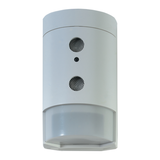
DD300-P Series Dual Technology Detector
Installation Sheet
EN DE ES FR
IT
NL
1a
1b
(1)
A
B
1d
2a
NON CONNECTE
F
R
RESERVE
NL
D
E
FREI
I
T
LIBERO
E
S
LIBRE
SPARE
ALARM
1
2
3
4
5
DD325-P
© 2012 UTC Fire & Security Americas Corporation, Inc.
All rights reserved.
(8)
(2)
(3)
(4)
(6)
5 cm
AUTOPROTECTION
SABOTAGE
SABOTAGE
ANTIMANOMISSIONE
ANTISABOTAJE
LED/
LED
TAMPER
SPARE
6
7
8
J3
LED
J2
J1
WALK TEST
RANGE
LED
1c
(5)
(7)
(9)
2.4 m nom.
2b
EN
NC
COMMON
F
R
NF
COMMUN
NL
NC
COMMON
D
E
NC
COMMON
I
T
NC
COMMUN
E
S
NC
COMMON
J1
12MTR
ALARM
8MTR
5MTR
3
RANGE
J2
DUAL
ULTRA-
SONIC
DD326-P
PIR
DD336-P
WALK TEST
LED
J3
ON
OFF/
REMOTE
LED
1 / 12
12 m
2c
NO
NON CONNECTE
TEST DE MARCHE
NO
RESERVE
NO
FREI
NO
LIBERO
PROVA DI MOVIMENTO
NA
LIBRE
PRUEBA DE ANDADO
NA
SPARE
LATCH
8
9
4
5
DD335-P
DD336-P
Dual = +12V
Dual = +12V
PIR = NC
PIR = NC
P/N 143541999-2 • REV C • ISS 29NOV12
LOOPTEST
GEHTEST
WALK
TEST
10
@ 9
@10
@ 9
@10
Advertisement
Table of Contents

Related Manuals for Interlogix DD300-P Series


Summary of Contents for Interlogix DD300-P Series
- Page 1 DD300-P Series Dual Technology Detector Installation Sheet EN DE ES FR 5 cm 2.4 m nom. 12 m NON CONNECTE AUTOPROTECTION COMMON NON CONNECTE TEST DE MARCHE RESERVE SABOTAGE COMMUN RESERVE LOOPTEST FREI SABOTAGE COMMON FREI GEHTEST LIBERO ANTIMANOMISSIONE COMMON...
-
Page 2: En: Installation Sheet
Break out one or both cable entry holes (item 5) as required. The DD300-P series detector is a verified PIR and should be Select mounting holes for corner (item 6) or flat wall installed to maximise PIR detection. The best detection is (item 7) mounting. -
Page 3: Range Adjustment
Select the required function of the LED at jumper J2. Caution: Ultrasonic disable. DD335-P/DD336-P has the additional feature that whenever the system is disarmed with • DUAL: Detector Alarm. The LED lights when the detector the walk test off, the ultrasonic transmitter will be switched off. is in alarm. - Page 4 Abdeckplatte wieder aufsetzen (Position 1). Der Melder sollte in einer Höhe von 1,8 bis 3,0 m angebracht Contact information werden. www.utcfireandsecurity.com or www.interlogix.com For customer support, see www.utcfssecurityproducts.eu LED Funktion beim Gehtest Siehe Abb. 2. DE: Installationsdatenblatt Die Schalterstellung ON ermöglicht die LED-Gehtest-Funktion...
-
Page 5: Technische Daten
Versorgungsspannung 9–15 V (12 V nom.) Max. Brummspannung 2 V (bei 12 V ) Kontaktinformation Stromaufnahme: www.utcfireandsecurity.com oder www.interlogix.com Normalbetrieb DD325-P, DD335-P: 18 mA Kontaktinformationen für den Kundendienst finden Sie unter DD326-P, DD336-P: 22 mA www.utcfssecurityproducts.de Bei Alarm max. 22 mA Montagehöhe... -
Page 6: Instrucciones De Montaje
Para la DD335-P/DD336-P se habilita el LED aplicando "CV" ES: Hoja de instalación en el terminal 10. Selección del funcionamiento del LED mediante el puente J2. Descripción • DUAL: Alarma del detector. Se activa el LED cuando el detector está en alarma. Relé según el estado del LED. La serie de detectores DD300-P es del tipo PIR verificado, y •... -
Page 7: Especificaciones Técnicas
Para obtener más información, consulte: modo doble tecnologia. www.recyclethis.info. Información de contacto Máscara para ventana www.utcfireandsecurity.com o www.interlogix.com Vea (fig. 4). Para acceder al servicio técnico, consulte En presencia de objetos demasiado cercanos (dentro de www.utcfssecurityproducts.es 1,5 m) y directamente bajo del detector, ajuste la máscara en el interior de la mirilla. -
Page 8: Caractéristiques
Pour le passage des câbles perforer l’opercule prevue à Mémoire d’alarme (DD335-P/DD336-P) cet effet à l’aide d’un tournevis ou utiliser un forêt de Voir fig. 2c. diamètre 6 mm. Le câble préconise comprend de 3 à 5 paires et est d’un diamètre exterieur de ~4,5 à 6 mm. Connecter un «... - Page 9 (oggetto 1). Il sensore dovrebbe essere montato ad un’altezza compresa Informations de contact tra 1,8 e 3,0 metri. www.utcfireandsecurity.com ou www.interlogix.com Pour contacter l'assistance clientèle, voir www.utcfssecurityproducts.fr/mail_support.htm P/N 143541999-2 • REV C • ISS 29NOV12 9 / 12...
-
Page 10: Caratteristiche Tecniche
Funzioni del LED e verifica di copertura andati in alarme verranno identificati dal led di allarme lampeggiante. Applicando di nuovo il riferimento "CV" "walk test" (reinserendo l’impianto) si ottiene il reset delle indicazioni di allarme. Vedere fig. 2. Per la verifica di copertura dei modelli DD325-P/DD326-P Abilitazione/disabilitazione remota del LED assicuratevi che il cavallotto J3 sia sulla poizione ON o che il LED sia abilitato da comando remoto (vedere sotto). -
Page 11: Installatie-Instructies
Informazioni di contatto Looptest LED funkties www.utcfireandsecurity.com o www.interlogix.com Zie fig. 2. Per l'assistenza clienti, vedere www.utcfssecurityproducts.it Voordat u de DD325-P/DD326-P kunt looptesten, dient u jumper J3 in de ON positie te zetten, of de LED dient op afstand te zijn ingeschakeld (zie hieronder). -
Page 12: Algemene Informatie
Vensterafdekkapje Contact informatie Zie fig. 4b. www.utcfireandsecurity.com of www.interlogix.com Voor mogelijke vals alarm bronnen, binnen het bereik van 1,5 Voor klantenondersteuning, zie www.utcfssecurityproducts.nl m of onder de detector, is het afdekkapje aan de binnenkant van het venster bevestigd. Hierdoor wordt het deel van het bereik van de gordijnvelden uitgeschakeld, dat anders de detector zou kunnen destabiliseren.