Endress+Hauser Liquiphant FTL64 Operating Instructions Manual
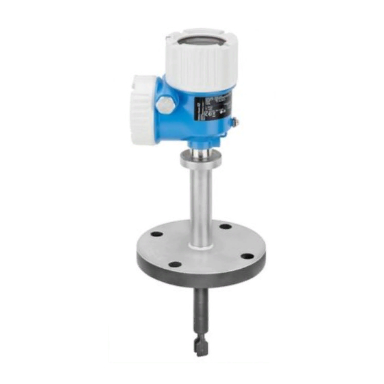
Vibronic point level switch for liquids in high-temperature applications
Hide thumbs
Also See for Liquiphant FTL64:
- Operating instructions manual (64 pages) ,
- Technical information (52 pages) ,
- Brief operating instructions (41 pages)

Related Manuals for Endress+Hauser Liquiphant FTL64


Summary of Contents for Endress+Hauser Liquiphant FTL64
- Page 1 Products Solutions Services BA02037F/00/EN/02.20 71498548 2020-11-30 Valid as of version 01.00.zz Operating Instructions Liquiphant FTL64 Vibronic Point level switch for liquids in high-temperature applications...
- Page 2 Liquiphant FTL64 Order code: XXXXX-XXXXXX Ser. no.: XXXXXXXXXXXX Ext. ord. cd.: XXX.XXXX.XX Serial number www.endress.com/deviceviewer Endress+Hauser Operations App A0023555 Endress+Hauser...
-
Page 3: Table Of Contents
Liquiphant FTL64 Table of contents Table of contents 6.2.2 3-wire DC-PNP (electronic insert About this document ....5 FEL62) ..... . . 19 Symbols . - Page 4 Table of contents Liquiphant FTL64 Maintenance ..... . 43 Index ........58 11.1 Maintenance tasks .
-
Page 5: About This Document
Liquiphant FTL64 About this document About this document Symbols 1.1.1 Safety symbols DANGER This symbol alerts you to a dangerous situation. Failure to avoid this situation will result in serious or fatal injury. WARNING This symbol alerts you to a dangerous situation. Failure to avoid this situation can result in serious or fatal injury. -
Page 6: Registered Trademarks
Registered trademarks The Bluetooth® word mark and logos are registered trademarks owned by the Bluetooth SIG, Inc. and any use of such marks by Endress+Hauser is under license. Other trademarks and trade names are those of their respective owners. Apple®... -
Page 7: Workplace Safety
It meets general safety standards and legal requirements. It also complies with the EU directives listed in the device-specific EU Declaration of Conformity. Endress+Hauser confirms this by affixing the CE mark to the device. -
Page 8: Product Design
Incoming acceptance and product identification Liquiphant FTL64 Product design A0042420 1 Product design Housing with electronic insert and cover, Bluetooth module or LED module are optional Temperature spacer with gas-tight welded glass feedthrough → 2 lengths available depending on the process... -
Page 9: Product Identification
• Enter the serial number on the nameplate into the Endress+Hauser Operations App or use the Endress+Hauser Operations App to scan the 2-D matrix code (QR Code) on the nameplate 4.2.1... -
Page 10: Installation
Installation Liquiphant FTL64 A0042422 3 Handling the device Installation WARNING Loss of protection rating if the device is opened in a wet environment. ‣ Only open the device in a dry environment! • Any orientation for device with short pipe up to approx. 500 mm (19.7 in) •... -
Page 11: Take Switch Point Into Consideration
Liquiphant FTL64 Installation If necessary, use external insulation. A0042298 5 Difference in temperature between outer and inner side of flange Insulation Temperature of flange, outer side Temperature of flange, inner side, for PFA (conductive) maximum 230 °C (446 °F) Difference in temperature for PFA (conductive) maximum 60 °C (140 °F) -
Page 12: Avoid Buildup
Installation Liquiphant FTL64 > 25 (0.98) A0042333 7 Installation example for low-viscosity liquids. Unit of measurement mm (in) Diameter of installation socket: at least 50 mm (2.0 in) High viscosity NOTICE Highly viscous liquids may cause switching delays. ‣... -
Page 13: Take Clearance Into Consideration
Liquiphant FTL64 Installation A0042345 9 Installation examples for a highly viscous process medium 5.1.5 Take clearance into consideration Allow sufficient space outside the tank for mounting, connection and settings involving the electronic insert. A0042340 10 Take clearance into consideration 5.1.6... -
Page 14: Mounting The Measuring Device
Installation Liquiphant FTL64 A0042356 11 Examples of support in the event of dynamic load Mounting the measuring device 5.2.1 Required tool • Open-ended wrench for sensor installation • Screwdriver for electrical connection 5.2.2 Installation Align the tuning fork with the marking Use the marking to align the tuning fork in such a way that medium can run off easily and deposit buildup is avoided. -
Page 15: Sliding Sleeves
Liquiphant FTL64 Installation A0034851 13 Marking and fork position Screwing in the device • Turn by the hex bolt only, 15 to 30 Nm (11 to 22 lbf ft) • Do not turn at the housing! A0042423 14... -
Page 16: Post-Installation Check
Electrical connection Liquiphant FTL64 Post-installation check Is the measuring device undamaged (visual inspection)? Does the measuring device conform to the measuring point specifications? For example: • Process temperature • Process pressure • Ambient temperature range • Measuring range ... -
Page 17: Connecting The Measuring Device
Liquiphant FTL64 Electrical connection Connecting the measuring device 6.2.1 2-wire AC (electronic insert FEL61) • Two-wire AC version • Switches the load directly into the power supply circuit via an electronic switch; always connect in series with a load • Functional testing without level change A functional test can be performed on the device using the test button on the electronic insert. - Page 18 Electrical connection Liquiphant FTL64 U 19...253 V AC I max: 350 mA >0,7 >0,5 L1 N A0036060 17 2-wire AC, electronic insert FEL61 Behavior of switch output and signaling ΔU <3.8 mA ΔU <3.8 mA <3.8 mA A0031901 18...
-
Page 19: 3-Wire Dc-Pnp (Electronic Insert Fel62)
Liquiphant FTL64 Electrical connection Selection tool for relays 207 230 253 A0042052 19 Recommended minimum holding power/rated power for load Holding power/rated power in [VA] Operating voltage in [V] AC mode • Operating voltage: 24 V, 50 Hz/60 Hz •... - Page 20 Electrical connection Liquiphant FTL64 Power consumption P ≤ 0.5 W Current consumption I ≤ 10 mA (without load) The red LED flashes in the event of an overload or short-circuit. Load current I ≤ 350 mA with overload and short-circuit protection Capacitance load C ≤ 0.5 µF at 55 V, C ≤ 1.0 µF at 24 V...
-
Page 21: Universal Current Connection With Relay Output (Electronic Insert Fel64)
Liquiphant FTL64 Electrical connection Behavior of switch output and signaling (L–) ΔU <100 µA (L–) (L–) ΔU <100 µA (L–) <100 µA (L–) A0033508 21 Behavior of switch output and signaling, electronic insert FEL62 MAX DIP switch for setting MAX safety mode... - Page 22 Electrical connection Liquiphant FTL64 According to IEC 61010, the following applies: Total voltage from relay outputs and power supply ≤ 300 V. Use electronic insert FEL62 DC PNP for small DC load currents, e. g. for connection to a PLC. Relay contact material: silver/nickel AgNi 90/10 When connecting a device with high inductance, provide a spark suppressor to protect the relay contact.
-
Page 23: Dc Connection, Relay Output (Electronic Insert Fel64 Dc)
Liquiphant FTL64 Electrical connection Behavior of switch output and signaling A0033513 23 Behavior of switch output and signaling, electronic insert FEL64 MAX DIP switch for setting MAX safety mode MIN DIP switch for setting MIN safety mode LED red for alarm... - Page 24 Electrical connection Liquiphant FTL64 When connecting a device with high inductance, provide spark quenching to protect the relay contact. A fine-wire fuse (depending on the connected load) protects the relay contact in the event of a short-circuit. Behavior of output signal •...
-
Page 25: Pfm Output (Electronic Insert Fel67)
Liquiphant FTL64 Electrical connection Behavior of switch output and signaling A0033513 25 Behavior of switch output and signaling, electronic insert FEL64 DC MAX DIP switch for setting MAX safety mode MIN DIP switch for setting MIN safety mode LED red for alarm... - Page 26 Electrical connection Liquiphant FTL64 Terminal assignment – >0,7 >0,5 A0036065 26 PFM output, electronic insert FEL67 8: Nivotester FTL325P 1 CH, FTL325P 3 CH input 1 33/ 34: Nivotester FTL325P 3 CH input 2 37/ 38: Nivotester FTL325P 3 CH input 3...
-
Page 27: 2-Wire Namur > 2.2 Ma/ < 1.0 Ma (Electronic Insert Fel68)
2-wire NAMUR > 2.2 mA/ < 1.0 mA (electronic insert FEL68) • For connection to the isolating switch repeater as per NAMUR (IEC 60947-5-6), e. g. Nivotester FTL325N from Endress+Hauser • Signal transmission H-L edge 2.2 to 3.8 mA/0.4 to 1.0 mA as per IEC 60947-5-6 (NAMUR) on two-wire cabling •... -
Page 28: Led Module Vu120 (Optional)
Electrical connection Liquiphant FTL64 Terminal assignment IEC 60947-5-6 8,2 V DC NAMUR – >0,7 >0,5 L- L+ A0036066 28 2-wire NAMUR ≥ 2.2 mA/≤ 1.0 mA, electronic insert FEL68 Behavior of switch output and signaling 2.2...3.8 mA 0.4...1.0 mA 2.2...3.8 mA... - Page 29 Liquiphant FTL64 Electrical connection Power consumption P ≤ 0.7 W, S < 6 VA Current consumption = 0.4 A Connecting the LED module A0033542 30 Connecting the LED module 1. Attach the connecting cable of the LED module to the connecting cables of the supply voltage.
-
Page 30: Bluetooth Module Vu121 (Optional)
Electrical connection Liquiphant FTL64 6.2.8 Bluetooth module VU121 (optional) A0039257 32 Bluetooth module VU121 • The Bluetooth module can be connected via the COM interface to the following electronic inserts: FEL61, FEL62, FEL64, FEL64 DC, FEL67, FEL68 (2-wire NAMUR). • The Bluetooth module is only available in conjunction with the Heartbeat Verification + Monitoring application package. -
Page 31: Connecting The Cables
Liquiphant FTL64 Electrical connection 6.2.9 Connecting the cables Required tool • Flat-blade screwdriver (0.6 mm x 3.5 mm) for terminals • Torque wrench A0018023 34 Example of coupling with cable entry, electronic insert with terminals M20 coupling (with cable entry), example Maximum conductor cross-section 2.5 mm... -
Page 32: Operation Options
Operation options Liquiphant FTL64 Operation options Overview of operation options 7.1.1 Operating concept • Operation with button and DIP switches on the electronic insert • Display with optional Bluetooth module and SmartBlue (app) via Bluetooth® wireless technology • Indication of operational status (switch status or alarm status) with optional LED module (lights visible from the outside) •... - Page 33 Liquiphant FTL64 Operation options FEL61 switching behavior and signaling <3.8 mA ΔU >1 s <3.8 mA <3.8 mA <3.8 mA A0039210 36 FEL61 switching behavior and signaling After the test button is pressed, the load is switched off for at least 10 s (I < 3.8 mA) even if the button is pressed for <...
- Page 34 Operation options Liquiphant FTL64 FEL64, FEL64DC switching behavior and signaling 3 4 5 6 7 8 3 4 5 6 7 8 >1 s 3 4 5 6 7 8 3 4 5 6 7 8 3 4 5 6 7 8...
-
Page 35: Functional Test Of The Electronic Switch With A Test Magnet
Liquiphant FTL64 Operation options 50 Hz 150 Hz >1 s 150 Hz 150 Hz 150 Hz A0039214 40 FEL67 MIN switching behavior and signaling After the test button is pressed, the output frequency is switched off for at least 10 s150 Hz, even if the button is pressed for <... -
Page 36: Heartbeat Diagnosis And Verification
Operation options Liquiphant FTL64 A0033419 42 Functional test with test magnet 7.1.4 Heartbeat diagnosis and verification with Bluetooth® wireless technology Access via Bluetooth® wireless technology A0033411 43 Remote operation via Bluetooth® wireless technology Smartphone or tablet with SmartBlue (app) -
Page 37: Led Module Vu120 (Optional)
Liquiphant FTL64 Commissioning LED module VU120 (optional) Depending on the MAX/MIN setting, an LED indicates the operational status (switch status or alarm status) in green, yellow and red. The LED lights up very brightly and can be easily identified from a distance. -
Page 38: Preparatory Steps
Commissioning Liquiphant FTL64 8.3.2 Preparatory steps Note down the ID number of the Bluetooth module. The ID number on the nameplate of the Bluetooth module is used as the initial password when establishing the connection for the first time. The high cover with the window must be used for devices that are operated with the Bluetooth module. -
Page 39: Operation
Liquiphant FTL64 Operation Operation Diagnostics menu The following data can be read out via the optional Bluetooth module and the associated Endress+Hauser SmartBlue app. 9.1.1 "Diagnostics" menu Settings and information concerning diagnostics as well as help for troubleshooting Diagnostics ‣... -
Page 40: System" Menu
Operation Liquiphant FTL64 ‣ Operating mode MIN/MAX setting Density setting Switching delay uncovered to covered Switching delay covered to uncovered ‣ Output Output state 9.1.3 "System" menu System settings concerning device management, user administration or safety System Electronic type ‣... -
Page 41: Heartbeat Verification
Liquiphant FTL64 Operation Time stamp of last proof test Date of proof test Frequency at delivery status Current frequency Upper alarm frequency Upper warning frequency Lower alarm frequency Battery status Electronics temperature Minimum electronics temperature Maximum electronics temperature Heartbeat Verification The "Heartbeat Verification"... -
Page 42: Diagnostics And Troubleshooting
Diagnostics and troubleshooting Liquiphant FTL64 Diagnostics and troubleshooting The device indicates warnings and faults via Bluetooth in the SmartBlue app and via the LEDs on the electronic insert. All the device warnings and faults are for information purposes only and do not have a safety function. The faults diagnosed by the device are displayed in the SmartBlue app in accordance with NE107. -
Page 43: Maintenance
Sterilization in Place Repair 12.1 General information 12.1.1 Repair concept Endress+Hauser repair concept • Measuring devices have a modular design • Customers can carry out repairs For more information on service and spare parts, please contact your Endress+Hauser sales representative. Endress+Hauser... -
Page 44: Repair Of Ex-Certified Devices
WARNING Limitation of electrical safety due to incorrect connection! Risk of explosion! ‣ Only specialist personnel or the Endress+Hauser service team may carry out repairs on Ex-certified devices. ‣ Relevant standards and national regulations on hazardous areas, safety instructions and certificates must be observed. - Page 45 Liquiphant FTL64 Repair In accordance with German law regulating the use of batteries (BattG §28 Para 1 Number 3), this symbol is used to denote electronic assemblies that must not be disposed of as household waste. Endress+Hauser...
-
Page 46: Accessories
Accessories Liquiphant FTL64 Accessories 13.1 Test magnet Order number: 71437508 A0039209 45 Test magnet 13.2 Weather protection cover for dual-compartment housing, aluminum • Material: stainless steel 316L • Order number: 71438303 229.4 (9.03) 136.7 (5.38) 81 (3.19) 103 (4.06) A0039231 ... -
Page 47: Plug-In Jack
Liquiphant FTL64 Accessories 13.4 Plug-in jack The plug-in jacks listed are suitable for use in the temperature range –25 to +70 °C (–13 to +158 °F). Plug-in jack M12 IP69 • Terminated at one end • Elbowed 90 ° • 5 m (16 ft) PVC cable (orange) •... -
Page 48: Led Module Vu120 (Optional)
Liquiphant FTL64 A0039257 50 Bluetooth module VU121 More detailed information is available: • Product Configurator on the Endress+Hauser web page: www.endress.com • Endress+Hauser Sales Center www.addresses.endress.com A tall cover is required (transparent plastic cover or aluminum cover with sight glass) when using or retrofitting the Bluetooth module. -
Page 49: High Pressure Sliding Sleeves
Liquiphant FTL64 Accessories M6 (3x) M6 (3x) G 1 A G 1½ A (1 NPT) (1½ NPT) A0037666 52 Sliding sleeves for unpressurized operation. Unit of measurement mm (in) = 0 bar (0 psi) G 1, DIN ISO 228/I •... - Page 50 Accessories Liquiphant FTL64 ø60 (2.36) ø60 (2.36) G 1 A G 1½A (1 NPT) (1½ NPT) A0037667 53 High pressure sliding sleeves. Unit of measurement mm (in) G 1, DIN ISO 228/I • Material: 1.4435 (AISI 316L) • Weight: 1.13 kg (2.49 lb) •...
-
Page 51: Technical Data
Liquiphant FTL64 Technical data Technical data 14.1 Input 14.1.1 Measured variable Level (point level), MAX or MIN safety 14.1.2 Measuring range Depends on the installation location and the pipe extension ordered Standard pipe extension up to 3 m (9.8 ft) and up to 6 m (20 ft) on request. -
Page 52: Output Signal
Ex connection data See safety instructions (XA): All data relating to explosion protection are provided in separate Ex documentation and are available from the Downloads Area of the Endress+Hauser-website. The Ex documentation is supplied as standard with all Ex devices. 14.3 Environment 14.3.1... - Page 53 Liquiphant FTL64 Technical data [°F] [°C] 158 70 -58 -50 [°C] [°F] [°F] [°C] 158 70 122 50 -58 -50 [°C] [°F] A0037923 54 Derating curve (Ambient temperature) 230 °C (446 °F) Sensor 280 °C (536 °F) Sensor Exception for electronic insert FEL64: Without LED module: Relais current = 6 A, T Max.
-
Page 54: Storage Temperature
Technical data Liquiphant FTL64 14.3.2 Storage temperature –40 to +80 °C (–40 to +176 °F) Optional: –50 °C (–58 °F), –60 °C (–76 °F) 14.3.3 Humidity Operation up to 100 %. Do not open in a condensing atmosphere. 14.3.4 Operating altitude As per IEC 61010-1 Ed.3:... -
Page 55: Process
Liquiphant FTL64 Technical data 14.4 Process 14.4.1 Process temperature range • –60 to +230 °C (–76 to +446 °F) • –60 to +280 °C (–76 to +536 °F) • –50 to +230 °C (–58 to +446 °F) with PFA coating (conductive) •... -
Page 56: Test Pressure
• With PFA coating (conductive): max. 40 bar (580 psi) max. 230 °C (446 °F) Ordering information: Product Configurator, order code for "Application" option "R" Devices with CRN approval: maximum 90 bar (1 305 psi) for devices with pipe extension. Information on the Endress+Hauser website: www.endress.com → Downloads. 14.4.4 Test pressure Test pressure = 1.5 · PN... -
Page 57: Additional Technical Data
Liquiphant FTL64 Technical data 14.5 Additional technical data Technical Documentation TI01540F. Endress+Hauser... - Page 58 Index Liquiphant FTL64 Index Access via Bluetooth® wireless technology ..36 CE mark (declaration of conformity) ....7 Check .
- Page 60 *71498548* 71498548 www.addresses.endress.com...