Endress+Hauser Liquiphant FTL62 Brief Operating Instructions
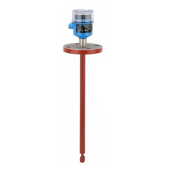
Vibronic point level switch with highly corrosion-resistant coating for liquids
Hide thumbs
Also See for Liquiphant FTL62:
- Operating instructions manual (60 pages) ,
- Brief operating instructions (32 pages) ,
- Operating instructions manual (36 pages)
Table of Contents
Advertisement
Quick Links
KA01479F/00/EN/02.22-00
71566287
2022-04-05
Products
Brief Operating Instructions
Liquiphant FTL62
Vibronic
Point level switch with highly corrosion-resistant
coating for liquids
These Instructions are Brief Operating Instructions; they are
not a substitute for the Operating Instructions pertaining to
the device.
Detailed information about the device can be found in the
Operating Instructions and the other documentation:
Available for all device versions via:
• Internet:
www.endress.com/deviceviewer
• Smart phone/tablet: Endress+Hauser Operations App
Solutions
Services
Advertisement
Table of Contents

Related Manuals for Endress+Hauser Liquiphant FTL62


Summary of Contents for Endress+Hauser Liquiphant FTL62
- Page 1 Operating Instructions pertaining to the device. Detailed information about the device can be found in the Operating Instructions and the other documentation: Available for all device versions via: • Internet: www.endress.com/deviceviewer • Smart phone/tablet: Endress+Hauser Operations App...
-
Page 2: Associated Documentation
Associated documentation Liquiphant FTL62 Associated documentation Order code: XXXXX-XXXXXX Ser. no.: XXXXXXXXXXXX Ext. ord. cd.: XXX.XXXX.XX Serial number www.endress.com/deviceviewer Endress+Hauser Operations App A0023555 About this document Symbols 2.1.1 Safety symbols DANGER This symbol alerts you to a dangerous situation. Failure to avoid this situation will result in serious or fatal injury. - Page 3 Liquiphant FTL62 About this document This symbol alerts you to a dangerous situation. Failure to avoid this situation can result in serious or fatal injury. CAUTION This symbol alerts you to a dangerous situation. Failure to avoid this situation can result in minor or medium injury.
-
Page 4: Basic Safety Instructions
Basic safety instructions Liquiphant FTL62 Basic safety instructions Requirements for the personnel The personnel must fulfill the following requirements to carry out the necessary tasks, e. g., commissioning and maintenance: ‣ Trained, qualified specialists must have a relevant qualification for the specific function and task ‣... -
Page 5: Product Safety
It meets the general safety standards and legal requirements. It also complies with the EU directives listed in the device-specific EU Declaration of Conformity. Endress+Hauser confirms this by affixing the CE mark to the device. Incoming acceptance and product identification... -
Page 6: Product Identification
All of the information on the measuring device is displayed along with an overview of the scope of technical documentation provided. • Enter the serial number on the nameplate into the Endress+Hauser Operations app or scan the 2-D matrix code on the nameplate with the Endress+Hauser Operations app 4.2.1... -
Page 7: Mounting Requirements
Liquiphant FTL62 Mounting Mounting instructions • Any orientation for device with short pipe up to approx. 500 mm (19.7 in) • Vertical orientation from above for device with long pipe • Minimum distance between the fork tip and the tank wall or pipe wall: 10 mm (0.39 in) A0042153 ... - Page 8 Mounting Liquiphant FTL62 Plastic-coated tuning fork A0042269 2 Typical switch points, plastic-coated tuning fork. Unit of measurement mm (in) Installation from above Installation from below Installation from the side Switch point Enamel-coated tuning fork A0043327 3 Typical switch points, enamel-coated tuning fork. Unit of measurement mm (in)
- Page 9 Liquiphant FTL62 Mounting Low viscosity It is permitted to position the tuning fork within the installation socket. > 25 (0.98) A0033297 4 Installation example for low-viscosity liquids. Unit of measurement mm (in) High viscosity NOTICE Highly viscous liquids may cause switching delays.
- Page 10 Mounting Liquiphant FTL62 5.1.3 Avoid buildup A0042206 6 Installation examples for a highly viscous process medium 5.1.4 Take clearance into consideration A0033236 7 Take clearance outside the tank into consideration Endress+Hauser...
-
Page 11: Mounting The Device
Liquiphant FTL62 Mounting 5.1.5 Support the device NOTICE If the device is supported incorrectly, shocks and vibrations can damage the coated surface. ‣ Only use a support in conjunction with ECTFE or PFA plastic coating. ‣ Only use suitable supports. - Page 12 Mounting Liquiphant FTL62 5.2.2 Aligning the tuning fork using the marking A0042207 9 Markings to align the tuning fork 5.2.3 Installing in pipes • Flow velocity up to 5 m/s with a viscosity of 1 mPa⋅s and density of 1 g/cm (SGU).
-
Page 13: Electrical Connection
Liquiphant FTL62 Electrical connection 5.2.4 Aligning the cable entry 4 3.5 Nm A0042214 11 Housing with external locking screw and drip loop The locking screw is not tightened when the device is delivered. Loosen the external locking screw (maximum 1.5 turns). -
Page 14: Connecting The Device
Electrical connection Liquiphant FTL62 0.7 Nm A0039520 12 Cover with securing screw 6.2.2 Connecting protective earth (PE) The protective earth conductor at the device must only be connected if the device' s operating voltage is ≥ 35 V or ≥ 16 V eff. -
Page 15: Current Consumption
Liquiphant FTL62 Electrical connection Current consumption Residual current when blocked: I ≤ 3.8 mA The red LED flashes in the event of an overload or short-circuit. Check for an overload or short-circuit every 5 s. The test is deactivated after 60 s. - Page 16 Electrical connection Liquiphant FTL62 Behavior of switch output and signaling ΔU <3.8 mA ΔU <3.8 mA <3.8 mA A0031901 14 Behavior of switch output and signaling, electronic insert FEL61 MAX DIP switch for setting MAX safety mode MIN DIP switch for setting MIN safety mode...
- Page 17 Liquiphant FTL62 Electrical connection Selection tool for relays 207 230 253 A0042052 15 Recommended minimum holding power/rated power for load Holding power/rated power in [VA] Operating voltage in [V] AC mode • Operating voltage: 24 V, 50 Hz/60 Hz •...
- Page 18 Electrical connection Liquiphant FTL62 Supply voltage WARNING Failure to use the prescribed power unit. Risk of potentially life-threatening electric shock! ‣ The FEL62 may only be powered by devices with safe galvanic isolation, as per IEC 61010-1. U = 10 to 55 V Comply with the following according to IEC/EN61010-1: provide a suitable circuit breaker for the device and limit the current to 500 mA, e.g.
- Page 19 Liquiphant FTL62 Electrical connection Terminal assignment U = 10...55 V DC 350 mA I max: 350 mA 55 V >0,7 >0,5 0.5 A L+ L- A0036061 16 3-wire DC-PNP, electronic insert FEL62 Connection wiring with terminals Connection wiring with M12 plug in housing as per EN61131-2 standard...
- Page 20 Electrical connection Liquiphant FTL62 Behavior of switch output and signaling (L–) ΔU <100 µA (L–) (L–) ΔU <100 µA (L–) <100 µA (L–) A0033508 17 Behavior of switch output and signaling, electronic insert FEL62 MAX DIP switch for setting MAX safety mode...
- Page 21 Liquiphant FTL62 Electrical connection Supply voltage U = 19 to 253 V , 50 Hz/60 Hz / 19 to 55 V Comply with the following according to IEC/EN61010-1: provide a suitable circuit breaker for the device and limit the current to 500 mA, e.g. by installing a 0.5 A fuse (slow-blow) in the power supply circuit.
- Page 22 Electrical connection Liquiphant FTL62 Terminal assignment >0,7 U = 19...55 V DC >0,5 U 19...253 V AC 0.5 A A0036062 18 Universal current connection with relay output, electronic insert FEL64 When bridged, the relay output works with NPN logic...
- Page 23 Liquiphant FTL62 Electrical connection Behavior of switch output and signaling A0033513 19 Behavior of switch output and signaling, electronic insert FEL64 MAX DIP switch for setting MAX safety mode MIN DIP switch for setting MIN safety mode LED red for alarm...
- Page 24 Electrical connection Liquiphant FTL62 Connectable load Loads switched via 2 potential-free changeover contacts (DPDT) • I ≤ 6 A (Ex de 4 A), U~ ≤ AC 253 V; P~ ≤ 1 500 VA, cos φ = 1, P~ ≤ 750 VA, cos φ > 0.7 • I ≤ 6 A (Ex de 4 A) to DC 30 V, I DC ≤...
- Page 25 Liquiphant FTL62 Electrical connection Terminal assignment >0,7 >0,5 U = 9...20 V DC 0.5 A L- PE A0037685 20 DC connection with relay output, electronic insert FEL64 DC When bridged, the relay output works with NPN logic Connectable load Endress+Hauser...
- Page 26 Electrical connection Liquiphant FTL62 Behavior of switch output and signaling A0033513 21 Behavior of switch output and signaling, electronic insert FEL64 DC MAX DIP switch for setting MAX safety mode MIN DIP switch for setting MIN safety mode LED red for alarm...
- Page 27 Liquiphant FTL62 Electrical connection Power consumption P ≤ 150 mW with Nivotester FTL325P or FTL375P Behavior of output signal • OK status: MAX operating mode 150 Hz, MIN operating mode 50 Hz • Demand mode: MAX operating mode 50 Hz, MIN operating mode 150 Hz •...
- Page 28 Electrical connection Liquiphant FTL62 Terminal assignment – >0,7 >0,5 L+ L- PE A0036065 22 PFM output, electronic insert FEL67 Connection wiring with terminals Connection wiring with M12 plug in housing according to EN61131-2 standard 8: Nivotester FTL325P 1 CH, FTL325P 3 CH input 1...
- Page 29 Liquiphant FTL62 Electrical connection Behavior of switch output and signaling 150 Hz 50 Hz 50 Hz 150 Hz 0 Hz A0037696 23 Switching behavior and signaling, electronic insert FEL67 MAX DIP switch for setting MAX safety mode MIN DIP switch for setting MIN safety mode...
-
Page 30: Power Consumption
Electrical connection Liquiphant FTL62 Supply voltage U = 8.2 V ±20 % Comply with the following according to IEC/EN61010-1: provide a suitable circuit breaker for the device. Power consumption NAMUR IEC 60947-5-6 < 6 mW with I < 1 mA; < 38 mW with I = 3.5 mA... - Page 31 Liquiphant FTL62 Electrical connection Behavior of switch output and signaling 2.2...3.8 mA 0.4...1.0 mA 2.2...3.8 mA 0.4...1.0 mA < 1.0 mA A0037694 25 Behavior of switch output and signaling, electronic insert FEL68 MAX DIP switch for setting MAX safety mode...
-
Page 32: Operation Options
Operation options Liquiphant FTL62 24/25 mm 8.0 Nm A0018023 26 Example of coupling with cable entry, electronic insert with terminals M20 coupling (with cable entry), example Conductor cross-section maximum 2.5 mm (AWG14), ground terminal on inside in housing + terminals on the electronics Conductor cross-section maximum 4.0 mm... - Page 33 Liquiphant FTL62 Operation options Elements on the electronic insert >0,7 >0,5 U = 9...20 V DC 3 4 5 A0037705 27 Example of electronic insert FEL64DC COM interface for additional modules (LED module, Bluetooth module) LED, red, for warning or alarm...
- Page 34 Commissioning Liquiphant FTL62 Commissioning Functional test using key on electronic insert • The functional test must be performed in the OK state: MAX safety and sensor free or MIN safety and sensor covered. • The LEDs flash one after another as a chaser light during the functional test.
-
Page 35: Switching On The Device
Liquiphant FTL62 Commissioning A0033419 30 Functional test with test magnet Switching on the device During the power-up time, the device output is in the safety-oriented state, or in the alarm state if available: • For electronic insert FEL61, the output will be in the correct state after a maximum of 4 sfollowing power-up. - Page 36 *71566287* 71566287 www.addresses.endress.com...