Endress+Hauser Liquiphant FTL51B Operating Instructions Manual
Vibronic point level switch for all kinds of liquids
Hide thumbs
Also See for Liquiphant FTL51B:
- Operating instructions manual (64 pages) ,
- Brief operating instructions (40 pages) ,
- Safety instruction (24 pages)

Related Manuals for Endress+Hauser Liquiphant FTL51B


Summary of Contents for Endress+Hauser Liquiphant FTL51B
- Page 1 Products Solutions Services BA01894F/00/EN/01.19 71442036 2019-04-01 Valid as of version 01.00.zz Operating Instructions Liquiphant FTL51B Vibronic Point level switch for all kinds of liquids...
- Page 2 Liquiphant FTL51B Order code: XXXXX-XXXXXX Ser. no.: XXXXXXXXXXXX Ext. ord. cd.: XXX.XXXX.XX Serial number www.endress.com/deviceviewer Endress+Hauser Operations App A0023555 Endress+Hauser...
-
Page 3: Table Of Contents
Liquiphant FTL51B Table of contents Table of contents 6.2.2 3-wire DC-PNP (electronic insert About this document ....5 FEL62) ..... . . 22 Symbols used . - Page 4 Table of contents Liquiphant FTL51B 10.2 Diagnostic information via light emitting 14.3.3 Humidity ..... 57 diodes ......46 14.3.4 Operating altitude .
-
Page 5: About This Document
Liquiphant FTL51B About this document About this document Symbols used 1.1.1 Safety symbols DANGER This symbol alerts you to a dangerous situation. Failure to avoid this situation will result in serious or fatal injury. WARNING This symbol alerts you to a dangerous situation. Failure to avoid this situation can result in serious or fatal injury. -
Page 6: Symbols In Graphics
About this document Liquiphant FTL51B Procedures, processes or actions that are forbidden. Indicates additional information. Reference to documentation … Series of steps Result of a step 1.1.5 Symbols in graphics Symbol Meaning 1, 2, 3 ... Item numbers … Series of steps A, B, C, ... -
Page 7: Basic Safety Instructions
Liquiphant FTL51B Basic safety instructions Basic safety instructions Requirements for the personnel The personnel for installation, commissioning, diagnostics and maintenance must fulfill the following requirements: ‣ Trained, qualified specialists must have a relevant qualification for this specific function and task. -
Page 8: Product Safety
It meets general safety standards and legal requirements. It also complies with the EC directives listed in the device-specific EC Declaration of Conformity. Endress+Hauser confirms this by affixing the CE mark to the device. -
Page 9: Product Description
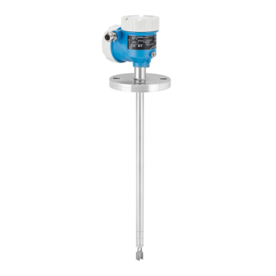
Liquiphant FTL51B Product description Product description Point level switch for MIN/MAX safety mode and density measurement Product design A0036953 Housing with cover, electronic insert and optional Bluetooth module or LED module Optional spacer (temperature spacer or pressure-tight feedthrough (second line of defense)) -
Page 10: Incoming Acceptance And Product
If required (see nameplate): Are the safety instructions (XA) provided? Is the device properly secured? If one of these conditions is not satisfied, contact your Endress+Hauser Sales Center. Product identification The measuring device can be identified in the following ways: •... -
Page 11: Storage And Transport
Liquiphant FTL51B Incoming acceptance and product identification Storage and transport 4.3.1 Storage conditions Use original packaging. Storage temperature –40 to +80 °C (–40 to +176 °F) 4.3.2 Handling of the device • Transport the device to the measuring point in the original packaging. -
Page 12: Installation
Installation Liquiphant FTL51B Installation The device can be installed in any position in a vessel, pipe or tank. A0037879 Temperature spacer for tank with insulation and/or high process temperatures. Installation conditions 5.1.1 Switch point Typical switch points, depending on the orientation of the point level switch (water +25 °C (+77 °F), 1 bar (14.5 psi). -
Page 13: Avoid Buildup
Liquiphant FTL51B Installation min. 25 (min. 1) A0033297 Installation socket diameter: at least 50 mm (2.0 in) High viscosity min. 40 (min. 1.6) A0037348 High viscosity (< 10 000 mPa·s), e.g. honey. The tuning fork must be located outside the installation socket! NOTICE High-viscosity liquids can cause switching delays. -
Page 14: Take Clearance Into Consideration
Installation Liquiphant FTL51B • Make sure there is sufficient distance between the tuning fork and vessel wall. There should be no contact between buildup on the vessel and buildup on the tuning fork. • The tuning fork must be able to project freely into the vessel. Use short installation sockets. -
Page 15: Mounting The Measuring Device
Liquiphant FTL51B Installation Mounting the measuring device 5.2.1 Required tools Open-ended wrench or socket wrench 32 AF (socket wrench can be ordered as an accessory → 50) 5.2.2 Installation Horizontal installation in vessels Use the marking to align the tuning fork in such a way that medium can run off easily and deposit buildup is avoided. - Page 16 Installation Liquiphant FTL51B The marking on the adapter points in the flow direction. Use the marking to align the tuning fork in such a way that the flow is not significantly obstructed. The marking can also be recognized when the device is installed, see the "Fork position marking"...
-
Page 17: Sliding Sleeves
Liquiphant FTL51B Installation Aligning the cable entry Housing with internal locking screw 3...4 x 0.7 Nm A0031876 Housing with external locking screw 0.7 Nm A0037347 Sliding sleeves See the "Accessories" section → 50 Post-installation check Is the device undamaged (visual inspection)? -
Page 18: Electrical Connection
Electrical connection Liquiphant FTL51B Electrical connection Connection conditions WARNING Supply voltage might be connected! Risk of electric shock and/or explosion! ‣ Ensure that no uncontrolled processes are activated in the system. ‣ Switch off the supply voltage before connecting the device. -
Page 19: Pe Connection
Liquiphant FTL51B Electrical connection Electronic insert Description Option 2-wire NAMUR > 2.2 mA/< 1.0 mA (FEL68) → 31 For separate switching unit Signal transmission H-L edge 2.2 to 3.8 / 0.4 to 1.0 mA as per EN 50227 (NAMUR) on two-wire cabling. - Page 20 Electrical connection Liquiphant FTL51B Output signal status • OK status: load on (switched through) • Demand mode: load off (blocked) • Alarm: load off (blocked) Terminal assignment NOTICE Device can be damaged. ‣ External load K must always be connected! The electronic insert has an integrated short-circuit connection.
- Page 21 Liquiphant FTL51B Electrical connection In the event of overload or no load, a current peak occurs for 1 minute every 5 seconds. DIP switch for setting the MAX safety mode → 37 DIP switch for setting the MIN safety mode → 37...
-
Page 22: 3-Wire Dc-Pnp (Electronic Insert Fel62)
Electrical connection Liquiphant FTL51B 6.2.2 3-wire DC-PNP (electronic insert FEL62) • Three-wire DC version • Preferred in conjunction with programmable logic controllers (PLC), DI modules as per EN 61131-2. Positive signal at the switch output of the electronics (PNP). • Functional testing without level change. Functional testing of the entire device can be performed using the test button on the electronic insert or with the test magnet with the housing closed. - Page 23 Liquiphant FTL51B Electrical connection Terminal assignment U = 10...55 V DC Imax. 350 mA I max: 350 mA Umax. 55 V >0,7 >0,5 4 3 1 0.5 A A0036061 Connection wiring with terminals Connection wiring with M12 connector in housing Behavior of the switch output and signalling (L–)
-
Page 24: Universal Current Connection With Relay Output (Electronic Insert Fel64)
Electrical connection Liquiphant FTL51B Functional test → 38 6.2.3 Universal current connection with relay output (electronic insert FEL64) • Universal current version with relay output • Switches the loads via 2 potential-free changeover contacts • Two galvanically isolated change-over contacts (DPDT), both change-over contacts switch simultaneously •... - Page 25 Liquiphant FTL51B Electrical connection Terminal assignment >0,7 U = 19...55 V DC >0,5 U 19...253 V AC 0.5 A A0036062 When bridged, the relay output works with NPN logic. Connectable load Behavior of the switch output and signalling A0033513 DIP switch for setting the MAX safety mode → 37 DIP switch for setting the MIN safety mode →...
-
Page 26: Dc Connection, Relay Output (Electronic Insert Fel64 Dc)
Electrical connection Liquiphant FTL51B 6.2.4 DC connection, relay output (electronic insert FEL64 DC) • Direct current version with relay output • Switches the loads via 2 potential-free changeover contacts • Two galvanically isolated change-over contacts (DPDT), both change-over contacts switch simultaneously •... - Page 27 Liquiphant FTL51B Electrical connection Terminal assignment >0,7 >0,5 U = 9...35 V DC 0.5 A A0037685 When bridged, the relay output works with NPN logic. Connectable load Behavior of the switch output and signalling A0033513 DIP switch for setting the MAX safety mode → 37 DIP switch for setting the MIN safety mode →...
-
Page 28: Pfm Output (Electronic Insert Fel67)
Electrical connection Liquiphant FTL51B 6.2.5 PFM output (electronic insert FEL67) • For connection to Endress+Hauser Nivotester switching units FTL325P and FTL375P • PFM signal transmission; current pulses are superimposed on the power supply along the two-wire cabling • • Functional testing without level change: •... - Page 29 Liquiphant FTL51B Electrical connection Terminal assignment – >0,7 >0,5 A0036065 / 8: Nivotester FTL325P 1CH, FTL325P 3CH / 34: Nivotester FTL325P 3CH / 38: NivotesterFTL325P 3CH / d2: Nivotester FTL375P 1CH Input 1 / z2: Nivotester FTL375P 2CH Input 2...
- Page 30 Electrical connection Liquiphant FTL51B Behavior of the switch output and signalling 150 Hz 50 Hz 50 Hz 150 Hz 0 Hz A0037696 DIP switch for setting the MAX safety mode → 37 DIP switch for setting the MIN safety mode → 37...
-
Page 31: 2-Wire Namur > 2.2 Ma/< 1.0 Ma (Electronic Insert Fel68)
Liquiphant FTL51B Electrical connection 6.2.6 2-wire NAMUR > 2.2 mA/< 1.0 mA (electronic insert FEL68) • For connection to isolation amplifiers as per NAMUR (IEC 60947-5-6), e.g. FTL325N from Endress+Hauser. • Signal transmission H-L edge 2.2 to 3.8 / 0.4 to 1.0 mA as per EN 50227 (NAMUR) on two-wire cabling •... -
Page 32: 2-Wire Density (Electronic Insert Fel60D) For Density Measurement
Electrical connection Liquiphant FTL51B Behavior of the switch output and signalling 2.2...3.8 mA 0.4...1.0 mA 2.2...3.8 mA 0.4...1.0 mA < 1.0 mA A0037694 DIP switch for setting the MAX safety mode → 37 DIP switch for setting the MIN safety mode → 37... - Page 33 Liquiphant FTL51B Electrical connection Terminal assignment Pulse – FML621 A0036059 Adjustment In the Liquiphant modular system, the option of an adjustment is also provided in addition to the electronics. There are three types of adjustment: • Standard adjustment In the standard adjustment, two fork parameters are determined to describe the sensor characteristics, indicated in the adjustment report and provided with the product.
- Page 34 Electrical connection Liquiphant FTL51B FML621 FML621 A0037880 Pressure and temperature information required depending on the application Liquiphant sensor with electronic insert FEL60D (pulse output) Temperature sensor (e.g. 4-20 mA output) Pressure transmitter (4-20 mA output) Liquiphant Density and Concentration Computer FML621 with display and operating unit...
-
Page 35: Led Module
Liquiphant FTL51B Electrical connection Functional test → 38 6.2.8 LED module The LED module may only be connected to the following electronic inserts: • FEL62 • FEL64 • FEL64 DC Wiring U 19...253 V AC I max: 350 mA >0,7... -
Page 36: Relay Output
Electrical connection Liquiphant FTL51B 6.2.10 Relay output • Universal current connection with relay output (FEL64): • Load AC: 253 V AC 6A (Ex de 4A) • Load DC: 125 V DC 0.2A 30 V DC 6A (Ex de 4A) • Pmax AC: 1500 VA, cos phi = 1 750 VA, cos phi > 0.7 •... -
Page 37: Operation Options
Liquiphant FTL51B Operation options Operation options Overview of operation options 7.1.1 Operating concept • Operation with button and DIP switches on the electronic insert → 37 • Display with optional Bluetooth module and SmartBlue (app) via Bluetooth® wireless technology → 40 •... - Page 38 Operation options Liquiphant FTL51B A fixed density setting of 0.4 can be ordered as an option. It is not possible to change this setting subsequently. Functional test using the button on the electronic insert >0,7 >0,5 U 19...253 V AC I max: 350 mA >0,7...
- Page 39 Liquiphant FTL51B Operation options 2.2 ... 3.5 mA 0.6 ... 1 mA >1 s 0.6 … 1 mA 0.6 ... 1 mA 0.6 ... 1 mA A0033543 Once the test button has been pressed, the current is 0.6 to 1 mA for at least 10 seconds, also if the button is pressed for <...
-
Page 40: Diagnostics And Verification With Bluetooth® Wireless Technology
Operation options Liquiphant FTL51B 7.1.3 Diagnostics and verification with Bluetooth® wireless technology A0033411 Smartphone / tablet with SmartBlue (app) Liquiphant with optional Bluetooth module Optional Bluetooth module Functions • Connection via COM interface: Bluetooth communication module for device diagnostics via a smartphone, tablet or laptop app •... -
Page 41: Led Indicator
Liquiphant FTL51B Commissioning The LED module can be used in conjunction with FEL62, FEL64 and FEL64DC. 7.2.1 LED indicator Setting Sensor state Sensor uncovered Lit green Sensor covered Lit yellow Sensor uncovered Lit yellow Sensor covered Lit green Alarm Lit red... -
Page 42: Advanced Settings
• iOS devices: iPhone 4S or higher from iOS9.0; iPad2 or higher from iOS9.0; iPod Touch 5th generation or higher from iOS9.0 • Devices with Android: from Android 4.4 KitKat and Bluetooth® 4.0 Endress+Hauser SmartBlue download, installation and starting. admin A0033339 1. -
Page 43: Functional Test Using The Button On The Electronic Insert
Liquiphant FTL51B Commissioning During the test, the current state of the electronic switch is reversed. 1. Make sure no undesired switching processes are triggered! 2. Wet approach (change the level or removal/installation with medium with a similar density and viscosity) with PTC ≥ 97% 3. -
Page 44: Protecting Settings From Unauthorized Access
Commissioning Liquiphant FTL51B 2.2 ... 3.5 mA 0.6 ... 1 mA >1 s 0.6 … 1 mA 0.6 ... 1 mA 0.6 ... 1 mA A0033543 Once the test button has been pressed, the current is 0.6 to 1 mA for at least 10 seconds, also if the button is pressed for <... -
Page 45: Operation
Liquiphant FTL51B Operation Operation Overview of the diagnostics menu The following data can be read out via the optional Bluetooth module and the associated Endress+Hauser app. Level 0 Level 1 Level 2 Level 3 Diagnosis Actual diagnostics Actual diagnostics Time stamp... -
Page 46: Diagnostics And Troubleshooting
Diagnostics and troubleshooting Liquiphant FTL51B Diagnostics and troubleshooting The device indicates warnings and errors via Bluetooth in the SmartBlue app and via the status LED. All warnings and errors are for information purposes only and do not perform a safety function. The errors which the device diagnoses are displayed in the SmartBlue app in accordance with NE107.The device behaves as in a warning or fault situation in... -
Page 47: Diagnostic Information On Local Display
Liquiphant FTL51B Diagnostics and troubleshooting Malfunction Possible cause Corrective action Device cannot be operated Incorrect password Enter correct password via SmartBlue entered Password forgotten Contact Endress+Hauser Service The sensor temperature is If the ambient temperature results in an increase in too high the sensor temperature of >60 °C (140 °F),... -
Page 48: Maintenance
Maintenance Liquiphant FTL51B Maintenance No special maintenance work is required. 11.1 Maintenance tasks 11.1.1 Cleaning The sensor must be cleaned if necessary. Cleaning can also be done while it is installed (e.g. CIP Cleaning in Place / SIP Sterilization in Place). Care must be taken to ensure that no damage occurs to the sensor in the process. -
Page 49: Repair
12.1.1 Repair concept The Endress+Hauser repair concept requires for devices to have a modular design and for repairs to be carried out by Endress+Hauser Service or by properly trained customers. Spare parts are grouped into logical kits with the associated replacement instructions. -
Page 50: Accessories
Accessories Liquiphant FTL51B Accessories 13.1 Device-specific accessories 13.1.1 Test magnet A0033419 Order number: 13.1.2 Weather protection cover for single-compartment housing A0038279 Material: stainless steel 316L Order number: 13.1.3 Weather protection cover for dual-compartment housing 115 (4.53) 140 (5.51) 32 (1.26) -
Page 51: M12 Connecting Cable
Liquiphant FTL51B Accessories 13.1.4 M12 connecting cable A0038278 DC-PNP NAMUR and DC-PNP Order number: Function: • Green light (3) is lit: Liquiphant is connected to the power supply and is ready for operation. • Yellow light (1) is lit: MAX mode of operation (overfill prevention): sensor is not immersed in liquid. -
Page 52: High Pressure Sliding Sleeves
Accessories Liquiphant FTL51B Thread Standard Material Order number Weight Approval DIN ISO 228/I 1.4435 (AISI 316L) 52003978 0.21 kg (0.46 lb) DIN ISO 228/I 1.4435 (AISI 316L) 52011888 0.21 kg (0.46 lb) With inspection certificate EN 10204 - 3.1 material NPT 1 ASME B 1.20.1... -
Page 53: Communication-Specific Accessories
Liquiphant FTL51B Accessories Thread Pressure/ Standard Material Weight Order number Approval temperature NPT 1½ ASME B 1.20.1 1.4435 (AISI 316L) 1.32 kg (2.91 lb) 52011883 With inspection certificate EN 10204 - 3.1 material NPT 1½ ASME B 1.20.1 AlloyC22 1.32 kg (2.91 lb) 71118695 With inspection certificate EN 10204 - 3.1... -
Page 54: Technical Data
Technical data Liquiphant FTL51B Technical data 14.1 Input 14.1.1 Measured variable Level 14.1.2 Measuring range Depends on the installation location and the pipe extension ordered Maximum sensor length 6 m (20 ft) 14.1.3 Density Density: >0.4 g/cm • Factory setting: density setting >0.7 g/cm •... -
Page 55: Output Signal
Liquiphant FTL51B Technical data 2. Switch off the supply voltage before connecting the device. 3. Remove the housing cover. 4. Guide cable through the gland. Preferably use a twisted, shielded two-wire cable. 5. Connect the device in accordance with the following diagram. -
Page 56: Signal On Alarm
Technical data Liquiphant FTL51B 14.2.3 Signal on alarm Alarm/output signal 14.2.4 Ex connection data See Safety instructions 14.3 Environment 14.3.1 Ambient temperature range In the hazardous area, the permitted ambient temperature can be limited depending on the zones and gas groups. Pay attention to the information in the Ex documentation (XA). -
Page 57: Storage Temperature
Liquiphant FTL51B Technical data Ordering information: • Product Configurator, order code for "Output", option "1" Ambient temperature –60 °C (–76 °F) can be ordered as an option. The low-temperature electronic inserts are marked LT. • Product Configurator, order code for "Output", option "2"... -
Page 58: Vibration Resistance
Technical data Liquiphant FTL51B 14.3.7 Vibration resistance As per IEC60068-2-64:2008 • a(RMS) = 50 m/s², f=5... 2000 Hz, t = 3 axes x 2 h • a(RMS) = 100 m/s², f=5... 2000 Hz, t = 3 axes x 2 h In the event of higher vibrations, we recommend the additional fitting: order code "Application"... -
Page 59: Process Pressure Range
Liquiphant FTL51B Technical data 14.4.3 Process pressure range [psi] [bar] 1450 +150 [°C] [°F] +302 A0038268 Permitted pressure rating if the "100 bar (1 450 psi)" option is selected. For exceptions, see the "Process connections" section. Canadian CRN approval: more details on the maximum pressure values are available in the download area of the product page under "www.endress.com". -
Page 60: Density Of The Process Medium
Technical data Liquiphant FTL51B ≤ 100 bar (1 450 psi) or 1.5 times the process medium pressure p Membrane burst pressure at 200 bar (2 900 psi) = 100 bar (1 450 psi): ≤ 150 bar (2 175 psi) or 1.5 times the process medium pressure p Membrane burst pressure at 400 bar (5 800 psi) The instrument function is limited during the pressure test. -
Page 61: Index
Liquiphant FTL51B Index Index CE mark ........8 Check . - Page 64 www.addresses.endress.com...