
Related Manuals for Extreme Networks ExtremeSwitching Virtual Services Platform 4450GTX-HT-PWR+


Summary of Contents for Extreme Networks ExtremeSwitching Virtual Services Platform 4450GTX-HT-PWR+
- Page 1 Installing the Virtual Services Platform 4450GTX-HT-PWR+ 9035362 Rev.02 August 2018...
- Page 2 Extreme Networks including the selection, arrangement and design ON BEHALF OF YOURSELF AND THE ENTITY FOR WHOM YOU of the content is owned either by Extreme Networks or its licensors ARE DOING SO (HEREINAFTER REFERRED TO and is protected by copyright and other intellectual property laws INTERCHANGEABLY AS “YOU”...
- Page 3 VIDEO IN COMPLIANCE WITH THE AVC STANDARD (“AVC consent of Extreme Networks can be a criminal, as well as a civil VIDEO”) AND/OR (II) DECODE AVC VIDEO THAT WAS ENCODED offense under the applicable law.
-
Page 4: Table Of Contents
.......................... 6 Training ...................... 6 Providing Feedback to Us .......................... 6 Getting Help .................... 7 Extreme Networks Documentation .................. 7 Subscribing to Service Notifications Chapter 2: New in this document.................... 9 Chapter 3: Hardware models.................... 10 ........................ 10 Management port ...................... 11 Platform power supplies .................. - Page 5 Contents .................... 33 Switch LED state indicators .................... 34 Port LED state indicators .................... 36 Viewing hardware information Chapter 6: Translations of safety messages................ 39 August 2018 Installing the Virtual Services Platform 4450GTX-HT-PWR+...
-
Page 6: Chapter 1: Preface
• Ideas for improvements to our documentation so you can find the information you need faster. • Broken links or usability issues. If you would like to provide feedback to the Extreme Networks Information Development team about this document, please contact us using our short online feedback form. -
Page 7: Extreme Networks Documentation
– A forum for Extreme customers to connect with one another, get questions answered, share ideas and feedback, and get problems solved. This community is monitored by Extreme Networks employees, but is not intended to replace specific guidance from GTAC. •... - Page 8 Preface About this task You can modify your product selections at any time. Procedure 1. In an Internet browser, go to http://www.extremenetworks.com/support/service-notification- form/ 2. Type your first and last name. 3. Type the name of your company. 4. Type your email address. 5.
-
Page 9: Chapter 2: New In This Document
Chapter 2: New in this document There are no feature-related changes for this release in Installing the Virtual Services Platform 4450GTX-HT-PWR+. August 2018 Installing the Virtual Services Platform 4450GTX-HT-PWR+... -
Page 10: Chapter 3: Hardware Models
11. Management port Extreme Networks Virtual Services Platform 4000 Series requires one port to be configured as the management port. This port separates user traffic from management traffic in highly sensitive environments, such as brokerages and insurance agencies. By using this dedicated network to manage the switch, and by configuring access policies (if you enable routing), you can manage the switch in a secure fashion. -
Page 11: Platform Power Supplies
Platform power supplies Platform power supplies The Virtual Services Platform 4450GTX-HT-PWR+ model supports two field-replaceable AC power supplies. One power supply is supplied with the chassis. You can install a redundant power supply to support load sharing or to provide power redundancy. The following table describes the Virtual Services Platform 4000 compatible AC power supplies and their part numbers (order codes). -
Page 12: Supported Optical Devices
VSP 4000 system. Important: The Extreme Networks SFP (1GigE) devices that are supported on the VSP 4850GTS can be used on the VSP 4450GTX-HT-PWR+ switch as they are certified and qualified as high temperature devices. - Page 13 System Software, NN47227-301. Compatible transceivers Important: Extreme Networks recommends using SFP and SFP+ transceivers as they have been through extensive qualification and testing. Extreme Networks will not be responsible for issues related to third party transceivers. • The VSP 4450GTX-HT-PWR+ operates in forgiving mode for SFP, and for coarse wave digital multiplexing (CWDM) and dense wave digital multiplexing (DWDM) SFP+ transceivers.
-
Page 14: Chapter 4: Preinstallation Checklist
Package contents on page 20 for a package. description of the components that are provided with the switch. If any components are missing, contact Extreme Networks support. Make sure that the power cord has the correct country-specific termination. Prepare the rack. - Page 15 Task Description in the area. The ground path must be permanent and must not exceed 1 Ohm of resistance from the rack to the grounding electrode. August 2018 Installing the Virtual Services Platform 4450GTX-HT-PWR+...
-
Page 16: Chapter 5: Installing The Vsp 4450Gtx-Ht-Pwr
Chapter 5: Installing the VSP 4450GTX-HT- PWR+ Installation checklist Use this checklist to install the VSP 4450GTX-HT-PWR+. Task Description Install the VSP 4450GTX-HT-PWR+. You can install the switch in two ways: • Installing the Virtual Services Platform 4000 on a table or shelf on page 21 •... -
Page 17: Electrostatic Discharge
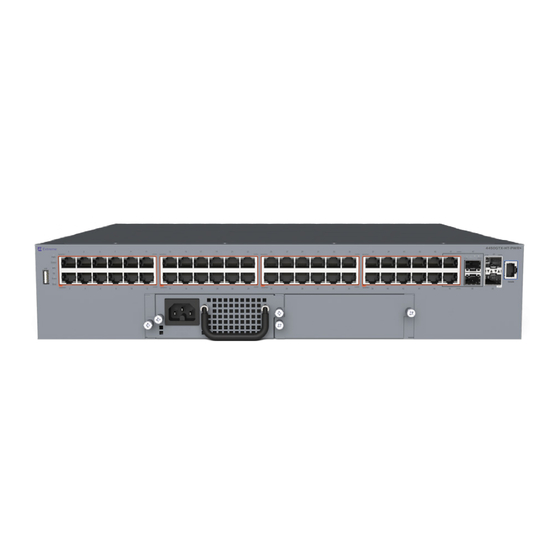
Electrostatic discharge 2. 2 Combo 100/1000 Mbps SFP ports supporting fiber or copper connection 3. 2 1/10 Gbps SFP+ ports for fiber or copper connection Figure 1: VSP 4450GTX-HT-PWR+ 1. USB 2.0 port Note: The VSP 4450GTX-HT-PWR+ model does not require a USB device in the USB port for normal operation. -
Page 18: Preventing Electrostatic Damage In New Cable Installations
Installing the VSP 4450GTX-HT-PWR+ • Ensure that you properly ground work surfaces and equipment racks for protection against electrostatic discharge. You must connect the common point to the building ground wire. In a properly wired building, the nearest reliable ground is typically at the electrical outlet. •... -
Page 19: Technical Specifications
Technical specifications Technical specifications The following table provides the technical specifications for the individual switches in this series. Ensure that the area where you install the switch and where it operates meets these requirements. Warning: To avoid bodily injury from hazardous electrical shock and current, never remove the top of the device. -
Page 20: Airflow Direction
Installing the VSP 4450GTX-HT-PWR+ Environmental requirement Virtual Services Platform 4000 models Miscellaneous Operating • No heat sources such as hot air vents or direct sunlight near the Considerations switch. • No sources of severe electromagnetic interference near the switch. • No excessive dust in the environment. •... -
Page 21: Installing The Virtual Services Platform 4000 On A Table Or Shelf
Installing the Virtual Services Platform 4000 on a table or shelf 3. Rubber footpads 4. Documentation that includes the following: a. Locating the latest software and product release notes for Virtual Services Platform 4000 Series b. Virtual Services Platform 4000 Series Regulatory Guide c. -
Page 22: Installing The Virtual Services Platform 4000 In An Equipment Rack
Installing the VSP 4450GTX-HT-PWR+ Installing the Virtual Services Platform 4000 in an equipment rack To install the VSP 4000 switch in an equipment rack, perform this procedure. Prerequisites for installing the VSP 4000 in an equipment rack: • Ensure that you have a space of 1.75 inches (4.45 centimeters) in height for each switch in an EIA or IEC-standard 19-inch (48.2-centimeter) equipment rack. - Page 23 Installing the Virtual Services Platform 4000 in an equipment rack 2. Slide the switch into the rack as illustrated. 3. Insert and tighten the rack-mount screws. August 2018 Installing the Virtual Services Platform 4450GTX-HT-PWR+...
-
Page 24: Cable Requirements For The Virtual Services Platform 4000
Installing the VSP 4450GTX-HT-PWR+ Cable requirements for the Virtual Services Platform 4000 The following table describes the cables required for the VSP 4000 switch. Table 7: Switch cable requirements Required Cable Description 10/100/1000BASE-T Ports The interconnect cabling must conform to the Cat5e, Cat6, or Cat6e specification of the Commercial Building Telecommunications Cabling Standard, ANSI/TIA/EIA 568-B fitted with an RJ45 Module jack. -
Page 25: Installing Sfp Transceivers
Installation and removal of Small Form Factor Pluggable (SFP) transceivers Installing SFP transceivers Install SFP transceivers by performing this procedure. 1. Remove the transceiver from the protective packaging. 2. Verify that the transceiver is the correct model for the network configuration. 3. -
Page 26: Rj45 Connector Pin Assignments
Installing the VSP 4450GTX-HT-PWR+ RJ45 connector pin assignments The following section describes the connector pin assignments for the RJ45 connectors in the Virtual Services Platform 4000 Series switches. Console port pin assignments The following table describes the console port pin assignments in the VSP 4000. Important: VSP 4000 supports only CLI Quickstart use on the console port. -
Page 27: Installing The Virtual Services Platform 4000 Power Supply
VSP 4000 hardware can vary. This procedure only applies to hardware models with field replaceable power supplies. Important: Extreme Networks does not support installing a combination of AC-input and DC-input power supplies in the same chassis. Procedure 1. If a blanking plate covers the required power supply slot, remove the blanking plate before attempting to insert the power supply. - Page 28 Installing the VSP 4450GTX-HT-PWR+ 1000W AC power supply VSP 4450GTX-HT-PWR+ supports dual 54V 1000W Power over Ethernet Plus (PoE+) AC power supplies. Important: Ensure that you use only 1000W power supplies (both primary and secondary) on VSP 4450GTX-HT-PWR+ models. Figure 3: 1000W AC power supply Connector The 1000W AC power supply uses an IEC 60320 C16 AC power cord connector.
-
Page 29: Connect Ac Power
Connect AC power Table 11: VSP 4450GTX-HT-PWR+ model with 1 PSU 0°C to 50°C 50°C to 70°C PoE support on 48 ports 23 ports PoE+ support on 26 ports 13 ports Table 12: VSP 4450GTX-HT-PWR+ model with 2 PSUs 0°C to 50°C 50°C to 70°C PoE support on 48 ports... -
Page 30: Power Cord Specifications
Installing the VSP 4450GTX-HT-PWR+ Power cord specifications To connect AC power to the switch, you need an appropriate AC power cord as described in the following table, also see the following table for plug specifications. Table 14: International power cord specifications Country and Plug Specification Specifications Typical Plug... - Page 31 Connect AC power Important: The VSP 4000 series has no AC power switch. When you connect the power cord to a suitable, energized AC power outlet, the switch powers up immediately. Figure 5: Connecting AC power to the front panel Warning: Disconnecting the AC power cord is the only way to turn off AC power to the VSP 4000.
-
Page 32: Led State Definitions
Installing the VSP 4450GTX-HT-PWR+ CP1 [03/24/14 18:39:08.000] LifeCycle: INFO: All processes have stopped CP1 [03/24/14 18:39:08.000] LifeCycle: INFO: All applications shutdown, starting power down sequence INIT: Sending processes the TERM signal Stopping OpenBSD Secure Shell server: sshdno /usr/sbin/sshd found; none killed cat: can't open '/proc/mtd': No such file or directory cat: can't open '/proc/mtd': No such file or directory... -
Page 33: Front Panel Leds
LED state definitions Front panel LEDs The following diagram illustrates the components on the front panels of the VSP 4450GTX-HT-PWR + switch. For detailed explanations of the states indicated by each front panel LED type, see the following sections: • Switch LED state indicators on page 33 •... -
Page 34: Port Led State Indicators
Installing the VSP 4450GTX-HT-PWR+ Label Color and Status Description Green (blinking) System is in reset. The switch is not receiving power and not operating. Status Green (solid) • During start-up: The power-on self-test (POST) is complete and the switch is operating normally. •... - Page 35 LED state definitions Table 16: RJ45 Port LED state indicators Label Color and Status Description Speed/PoE+ Green, Blink The port is set to operate at 1000 Mbps with PoE. Green, Steady The port is set to operate at 1000 Mbps without PoE+. Amber, Blink The port is set to operate at 100 Mbps with PoE+.
-
Page 36: Viewing Hardware Information
: 0 day(s), 00:05:40 SysContact : http://www.extremenetworks.com/contact/ SysLocation : 9 Northeastern Blvd,Salem,NH. 03079 Chassis Info: Chassis : 4450GTXHT-PWR+ ModelName : 4450GTXHT-PWR+ BrandName : Extreme Networks. Serial# : SDNIVSP4450B020 H/W Revision : R0B H/W Config : none Part Number NumSlots NumPorts : 50... - Page 37 Viewing hardware information Fan Info : Description OperStatus OperSpeed AirflowDir Tray 1 Fan 1 mediumSpeed left-right Tray 1 Fan 2 mediumSpeed left-right Tray 1 Fan 3 mediumSpeed left-right Tray 1 Fan 4 mediumSpeed left-right Tray 1 Fan 5 mediumSpeed left-right LED Info : LED#1 Label : PWR...
- Page 38 Installing the VSP 4450GTX-HT-PWR+ Variable Value Displays information about installed cooling ports. Displays LED information in detail. power Displays information about installed power supplies. temperature Displays temperature information. uboot Displays uboot details. August 2018 Installing the Virtual Services Platform 4450GTX-HT-PWR+...
-
Page 39: Chapter 6: Translations Of Safety Messages
Chapter 6: Translations of safety messages Caution: When you mount this device in a rack, do not stack units directly on top of one another. You must secure each unit to the rack with appropriate mounting brackets. Mounting brackets cannot support multiple units. Important: Achtung: Wenn diese Einheit in einem Rack montiert wird, muß... - Page 40 Translations of safety messages Caution: If you are not installing a module in the slot, be sure to keep the metal cover plate in place over the slot. Removing the cover plate impedes airflow and proper cooling of the unit. Important: Achtung: Wenn Sie kein Modul im Schacht verwenden, muß...
- Page 41 Warning: Disconnecting the AC power cord is the only way to turn off AC power to this device. Always connect the AC power cord in a quickly and safely accessible location in case of an emergency. Important: Warnung: Das Gerät kann nur durch Ziehen des Netzsteckers ausgeschaltet werden. Schließen Sie das Netzkabel an einer Steckdose an, die in Notfällen schnell und sicher zugänglich ist.
- Page 42 L'assenza di un percorso per la messa a terra verso lo switch può comportare un eccesso di emissioni. Warning: The lithium battery is not field replaceable. It must only be removed and replaced by authorized personnel. Contact Extreme Networks Technical Support for assistance if the battery requires replacement. Important: Warnung: Die Lithiumbatterie kann nicht vor Ort ausgetauscht werden.
- Page 43 Important: Aviso: A bateria de lítio não é substituível em campo. Só deve ser removida e substituída por pessoal autorizado. Entre em contato com o Suporte Técnico da Extreme Networks para obter assistência, se a bateria precisar de substituição. Important: Предупреждение:...