Extreme Networks Summit 300-24 Hardware Installation Manual
Summit 200 e, 300 e, 400 e, i series
Hide thumbs
Also See for Summit 300-24:
- Hardware installation manual (112 pages) ,
- Hardware installation manual (394 pages)
Table of Contents

Related Manuals for Extreme Networks Summit 300-24


Summary of Contents for Extreme Networks Summit 300-24
-
Page 1: Hardware Installation Guide
Extreme Networks Consolidated “i” and “e” Series Hardware Installation Guide Extreme Networks, Inc. 3585 Monroe Street Santa Clara, California 95051 (888) 257-3000 http://www.extremenetworks.com Published: October, 2005 Part number: 100093-00 Rev. 09... - Page 2 Solution Partners Logo, ServiceWatch, Summit, the Summit7i Logo, and the Color Purple, among others, are trademarks or registered trademarks of Extreme Networks, Inc. or its subsidiaries in the United States and other countries. Other names and marks may be the property of their respective owners.
-
Page 3: Table Of Contents
Site Preparation Planning Your Site Step 1: Meeting Site Requirements Step 2: Planning for Stacking (Summit “e” Series Only) Step 3: Evaluating and Meeting Cable Requirements Step 4: Meeting Power Requirements Extreme Networks Consolidated "i" and "e" Series Hardware Installation Guide... - Page 4 Summit 200 Automatic Failover Full-Duplex Support Summit 300 “e” Series Switches Summit 300 Features Summit 300-24 Switch Summit 300-48 Switch Summit 300-48 Switch LEDs Load Sharing Power Supplies Summit 300 Automatic Failover Extreme Networks Consolidated "i" and "e" Series Hardware Installation Guide...
- Page 5 Console Port Modem Port Ethernet Management Port PCMCIA Slot Power Sockets Label Summit1i, Summit5i, Summit7i, and Summit48i Switch LEDs Summit48i Switch LEDs GBIC Ports Power Sockets Label Reset Button Console Port Extreme Networks Consolidated "i" and "e" Series Hardware Installation Guide...
- Page 6 Disconnecting a Power Cable with an Installed Cable Retaining Bracket Installing the Summit48si Switch DC Power Supply Preparing and Attaching the DC Power Supply Cable Attaching the Connector to the DC Power Supply Extreme Networks Consolidated "i" and "e" Series Hardware Installation Guide...
- Page 7 Removing the Alpine 3808 or Alpine 3804 DC Power Supply Installing the Alpine 3800 Series Switch External Power Supply Rack-Mounting the EPS-LD Unit Connecting the EPS-LD to the FM-32Pi Module Removing an EPS-LD Unit Extreme Networks Consolidated "i" and "e" Series Hardware Installation Guide...
- Page 8 Removing the Alpine 3808 or Alpine 3804 Fan Tray Installing the Alpine 3808 or Alpine 3804 Fan Tray Part 5 BlackDiamond Switch Chapter 12 BlackDiamond 6800 Series Switch Overview Features Port Connections Extreme Networks Consolidated "i" and "e" Series Hardware Installation Guide...
- Page 9 Chapter 15 BlackDiamond 6800 Series Management Switch Fabric Module Overview of the BlackDiamond Management Switch Fabric Module MSM Activity MSM Memory MSM LEDs Installing MSMs Verifying the MSM Installation Replacing MSMs Extreme Networks Consolidated "i" and "e" Series Hardware Installation Guide...
- Page 10 Initial Switch and Management Access Connecting Equipment to the Console Port Logging In for the First Time Part 7 Appendixes Appendix A Safety Information Important Safety Information Power Power Cable Fuse Extreme Networks Consolidated "i" and "e" Series Hardware Installation Guide...
- Page 11 Installing GBICs and Mini-GBICs Installing GBICs Safety Information Preparing to Install or Replace a GBIC Installing or Replacing a GBIC Installing Mini-GBICs Safety Information Preparing to Install or Replace a Mini-GBIC Extreme Networks Consolidated "i" and "e" Series Hardware Installation Guide...
- Page 12 Installing or Replacing a Mini-GBIC Appendix E Installing the Summit Option Card and XENPAK Modules Installing the Summit Option Card Installing a XENPAK Optical Transceiver Module Removing a XENPAK Module Index Extreme Networks Consolidated "i" and "e" Series Hardware Installation Guide...
-
Page 13: Preface
This preface provides an overview of this guide, describes guide conventions, and lists other publications that might be useful. NOTE To ensure proper operation of your Extreme Networks equipment, read this guide before you install any Extreme Networks equipment. Introduction ®... -
Page 14: Conventions
• Routing concepts • Simple Network Management Protocol (SNMP) See the ExtremeWare Software User Guide for information about configuring an Extreme Networks switch. NOTE If the information in the Release Notes shipped with your switch differs from the information in this guide, follow the Release Notes. -
Page 15: Related Publications
• ExtremeWare Software User Guide • ExtremeWare Software Command Reference Guide • ExtremeWare Release Notes Documentation for Extreme Networks products is available from the Extreme Networks website at the following location: http://www.extremenetworks.com/services/documentation/ You can select and download the following Extreme Networks documentation from the Documentation section of the Services page: •... -
Page 16: About This Guide
Preface About This Guide This guide describes how to prepare your site and how to install, maintain, and operate your Extreme Networks switch. It contains information about features that are common to all switches, as well as switch-specific features. This guide contains seven parts: •... - Page 17 Appendix E, “Installing the Summit Option Card and XENPAK Modules” describes how to install the Summit Option Card and associated XENPAK modules to add high-performance uplink ports to the switch. Extreme Networks Consolidated "i" and "e" Series Hardware Installation Guide...
- Page 18 Preface Extreme Networks Consolidated "i" and "e" Series Hardware Installation Guide...
-
Page 19: Part 1 Common Features
Part 1 Common Features... -
Page 21: Common Switch Features
Common Switch Features This chapter describes the features that are shared in common by the Extreme Networks family of switches. The following topics are described in detail: • Software Images on page 21 • Full-Duplex Support on page 22 • Management Ports on page 22 •... -
Page 22: Full-Duplex Support
• BlackDiamond—Management Switch Fabric Module (MSM64i) for the BlackDiamond series switch. Extreme Networks does not recommend that you use the management port to route traffic to any front panel port on the switch. The management port is designed for switch management purposes. -
Page 23: Mini-Gbic Type And Hardware/Software Support
Instructions to install mini-GBICs are in Appendix D, “Installing GBICs and Mini-GBICs”. GBIC Type and Hardware/Software Support Most Extreme Networks switches support two types of GBICs: the Parallel ID GBIC and the Serial ID GBIC. The switch can identify the media type for the GBIC that is installed. Initial ExtremeWare software versions do not support Serial ID GBICs. - Page 24 Common Switch Features Extreme Networks Consolidated "i" and "e" Series Hardware Installation Guide...
-
Page 25: Part 2 Site Planning
Part 2 Site Planning... - Page 27 Site Preparation This chapter describes how to prepare your site for installing Extreme Networks equipment. It contains information about environmental and cabling requirements, power requirements, and building and electrical code organizations. This chapter includes these sections: • Planning Your Site on page 28 •...
-
Page 28: Chapter 2 Site Preparation
If you will be installing Summit “e” series switches in a stacked configuration, make sure you have the appropriate cables for the interconnections. To use the dedicated stacking ports on the back of the Summit 400 series switches, you must have a special cable that is available from Extreme Networks. Step 3: Evaluating and Meeting Cable Requirements... -
Page 29: Operating Environment Requirements
United States according to the Communications Act of 1934. The FCC regulates all U.S. telephone and cable systems. The address is FCC; 1919 M Street N.W.; Washington, D.C. 20554 USA. Extreme Networks Consolidated "i" and "e" Series Hardware Installation Guide... - Page 30 Extreme Networks recommends that you consult an electrical contractor for commercial building and wiring specifications. Temperature. Extreme Networks equipment generates a significant amount of heat. It is essential that you provide a temperature-controlled environment for both performance and safety. Install the equipment only in a temperature- and humidity-controlled indoor area that is free of airborne materials that can conduct electricity.
- Page 31 Make sure there is space around the installed switch for airflow and that cables or other equipment do not block the air intake or outflow vents on the Extreme Networks switches. It is best to have 3 to 5 inches (7.62 to 12.7 cm) of clear space in front of the air intake and outflow vents on the switches.
- Page 32 • Airflow for cooling power supplies moves left to right as you face the chassis. • Airflow for cooling modules moves left to right as you face the chassis. Figure 2: Airflow through the Alpine 3804 chassis Airflow through chassis Airflow through chassis 38_air4 Extreme Networks Consolidated "i" and "e" Series Hardware Installation Guide...
- Page 33 Meeting Site Requirements Figure 3: Airflow through the Alpine 3802 chassis Airflow through chassis Airflow through chassis 3802air Extreme Networks Consolidated "i" and "e" Series Hardware Installation Guide...
- Page 34 • Airflow for cooling modules moves left to right as you face the chassis. Figure 4: Airflow through the BlackDiamond 6816 chassis Airflow through chassis Airflow through power supplies BD_032 Extreme Networks Consolidated "i" and "e" Series Hardware Installation Guide...
- Page 35 Figure 5: Airflow through the BlackDiamond 6808 chassis 50015 50015 Airflow through chassis POWER POWER DC OUT DC OUT AC IN AC IN 50021 50021 Airflow through power supplies BD_027 Extreme Networks Consolidated "i" and "e" Series Hardware Installation Guide...
- Page 36 Automatic Shutdown in an Overheating Condition. The power supply controls the overheating shutdown condition in the system. The power will shut down at approximately 85° C (+/- 5° C) as reported on an independent temperature sensor within the power supply. Extreme Networks Consolidated "i" and "e" Series Hardware Installation Guide...
- Page 37 The temperature sensor remains active when the system is in a shutdown state. System Alarms in an Overheating Condition. Extreme supports the following SNMP alarms to report overheating conditions: • Over Temperature Alarm: This trap sends notification of an overheating condition, but takes no action.
- Page 38 • Use electrostatically safe equipment and the ESD straps that are provided with your equipment. All Alpine and BlackDiamond switches come with ESD wrist strap connectors and wrist straps as shown in Figure 7. Extreme Networks Consolidated "i" and "e" Series Hardware Installation Guide...
-
Page 39: Rack Specifications And Recommendations
• The rack should use the universal mounting rail hole pattern that is identified in IEC Standard 297. • The mounting holes should be flush with the rails to accommodate the chassis. • Use a rack made of steel or aluminum. Extreme Networks Consolidated "i" and "e" Series Hardware Installation Guide... - Page 40 Use a rack grounding kit and a ground conductor that is carried back to earth or to another suitable building ground. All Extreme Networks switches are designed with mounting brackets that provide solid metal-to-metal connection to the rack. If you do not use equipment racks, you can attach wiring terminals directly to the mounting brackets for appropriate grounding.
-
Page 41: Planning For Stacking
The Summit 400 series switches also have an assigned platform weight for installed 10-gigabit dual uplink ports (Summit XEN or XGM-2xn Option Card). Table 5 lists the platform weights. Extreme Networks Consolidated "i" and "e" Series Hardware Installation Guide... - Page 42 Platform weight for Summit XEN option card = 2 Platform weight for the Summit 400-24 = 2 Let the supported number of slots of Summit 400-24 switches in this configuration = y Extreme Networks Consolidated "i" and "e" Series Hardware Installation Guide...
-
Page 43: Planning Switch Placement In The Rack
• If only Summit 400 series switches are in the stack, stacking connections happen at the back of the switch using the Extreme Networks-specified stacking cable and the dedicated stacking ports. • Stacking Summit 200 or 300 series switches with Summit 400 series switches is not supported. -
Page 44: Evaluating And Meeting Cable Requirements
We recommend using the BICSI (Building Industry Consulting Service International) RCDD (Registered Communications Distribution Designer), which is globally recognized as a standard in site planning and cabling. For information, go to http://www.bicsi.org Extreme Networks Consolidated "i" and "e" Series Hardware Installation Guide... -
Page 45: Cable Labeling And Record Keeping
• Assign a unique block of sequential numbers to the group of cables that run between each pair of wiring closets. • Assign a unique identification number to each distribution rack. • Identify all wiring closets by labeling the front panel of your Extreme Networks equipment and other hardware. • Keep accurate and current cable identification records. - Page 46 It is also important not to stretch the cable during installation. We recommend that the bend radius for fiber optic cable equals 2-inch (5.08 cm) minimum for each 90 degree turn as shown in Figure 12. Extreme Networks Consolidated "i" and "e" Series Hardware Installation Guide...
- Page 47 70,000 (1550 nm optical window) 100BASE-FX 50/125 µm multimode fiber 2000 (1300 nm optical 50/125 µm multimode fiber 2000 window) 62.5/125 µm multimode fiber 2000 62.5/125 µm multimode fiber 2000 Extreme Networks Consolidated "i" and "e" Series Hardware Installation Guide...
-
Page 48: Rj-45 Connector Jackets
10BASE-T Category 3 and higher UTP cable – Proprietary to Extreme Networks. Connections between two Extreme Networks 1000BASE-LX interfaces that use 10/125 µm single-mode fiber can use a maximum distance of 10,000 meters. RJ-45 Connector Jackets Use cable with RJ-45 connector jackets that are flush with the connector or that have connectors with a no-snag feature. -
Page 49: Making Network Interface Cable Connections
In areas or applications where these situations cannot be avoided, use fiber optic cabling or shielded twisted pair cabling (STP). NOTE Because harmonics can appear on the neutral line of a typical three-phase power circuit, Extreme Networks recommends using a harmonics meter in new installations. Making Network Interface Cable Connections Use the appropriate type of cable to connect the ports of your switch to another switch or router. -
Page 50: Power Supply Requirements
Site Preparation For more information about the power specifications of the Extreme Networks family of switches, see Appendix B, “Switch Technical Specifications”. Power Supply Requirements Adhere to the following requirements in order to operate your Extreme Networks equipment safely: • Make sure your equipment is placed in an area that accommodates the power consumption and component heat dissipation specifications. -
Page 51: Dc Power Requirements
For BlackDiamond DC power cables, use 4 AWG, high strand-count copper wire cable. Summit48si International • • For the Summit48si DC power cable, use the three-wire harness that was shipped with the Summit48si switch and power supply. Extreme Networks Consolidated "i" and "e" Series Hardware Installation Guide... -
Page 52: Replacing The Power Cable
• Where will the UPS be installed? • What is the maximum transition time that your installation will allow? NOTE Extreme Networks recommends that you use a UPS that provides online protection. Extreme Networks Consolidated "i" and "e" Series Hardware Installation Guide... -
Page 53: Applicable Industry Standards
This section provides information about the optical and system budgets for GBICs and mini-GBICs. Optical Budgets for Mini-GBICs The total optical system budget for the SX mini-GBIC is 11.5 dB. Extreme Networks recommends that 3 dB of the total budget be reserved for losses induced by cable splices/connectors and operating margin. -
Page 54: Long-Range Gbic System Budgets
(for example, 0.25 db/km), Extreme Networks recommends that 3 dB of the total budget be reserved for losses induced by cable splices, connectors, and operating margin. Figure 14 shows the total optical system budget between long range GBICs. - Page 55 ZX Rev 03 8 dB 8 dB 8 dB 9 dB LX100 11 dB 11 dB 11 dB 12 dB The ZX mini-GBIC is equivalent to the ZX Rev 03 GBIC. Extreme Networks Consolidated "i" and "e" Series Hardware Installation Guide...
- Page 56 Site Preparation Extreme Networks Consolidated "i" and "e" Series Hardware Installation Guide...
-
Page 57: Part 3 Summit Switch
Part 3 Summit Switch... - Page 59 — Summit 400-24t and 400-24p switches — Summit 400-48t switch • Summit1i on page 88 • Summit5i on page 90 • Summit7i on page 93 • Summit48i on page 97 • Summit48si on page 100 Extreme Networks Consolidated "i" and "e" Series Hardware Installation Guide...
-
Page 60: Chapter 3 Summit Switch Models
200-48 switches) • 24 100BASEFX ports using LC connectors (Summit 200-24fx switch) • Two 10/100/1000BASE-T Gigabit Ethernet uplink ports using RJ-45 connectors • Two optical ports that allow Gigabit Ethernet uplink connections through Extreme mini-GBICs: — 1000BASE-SX — 1000BASE-LX — 1000BASE-ZX —... -
Page 61: Summit 200 Series Switch Physical Description
Figure 17: Summit 200-24fx switch front view RJ-45 GBIC Console ports ports port Unit stacking LC duplex fiber connectors ID LED ES20024fx_002 Figure 18: Summit 200-24fx switch rear view Power socket ES20024fx_001 Extreme Networks Consolidated "i" and "e" Series Hardware Installation Guide... -
Page 62: Summit 200 Switch Leds
The Summit 200 switch certification and safety label is located on the bottom of the switch. Summit 200 Switch LEDs Table 11 describes the LED activity for all three models of the Summit 200 switch. Extreme Networks Consolidated "i" and "e" Series Hardware Installation Guide... -
Page 63: Console Port
Port Connections A Summit 200-24 or 200-48 switch has either 24 or 48 10BASE-T/100BASE-TX ports using RJ-45 connectors for communicating with end stations and other devices over 10/100Mbps Ethernet. Extreme Networks Consolidated "i" and "e" Series Hardware Installation Guide... -
Page 64: Summit 200 Automatic Failover
Summit switch stack, see the ExtremeWare Software User Guide. NOTE Only mini-GBICs that have been certified by Extreme Networks (available from Extreme Networks) should be inserted into the mini-GBIC receptacles on the Summit 200 series switch. Summit 200 Automatic Failover The Summit 200 switch supports an automatic failover from an active fiber port to a copper backup or from an active copper port to a fiber port. -
Page 65: Full-Duplex Support
The copper port operates as an autonegotiating 10/100/1000BASE-T port. The optical port allows Gigabit Ethernet uplink connections through Extreme small form factor pluggable (SFP) gigabit interface connectors (GBICs), also known as mini-GBICs. Only one port in the combination pair can be... -
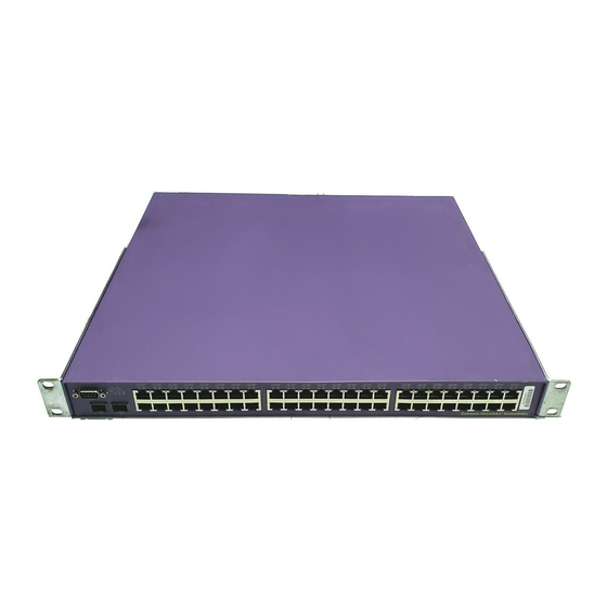
Page 66: Summit 300-24 Switch
10/100/1000BASE-T ports using RJ-45 connectors or optical ports using mini-GBICs. The Summit 300-24 switch can be interconnected with other Summit 300-24 switches or Summit 200 series switches to form a stacked configuration that is managed as a single switch entity. In a Summit stacked configuration, the uplink ports provide interconnection between the stacked switches. - Page 67 Mini-GBIC/ 1000-baseX ports RVN24001A The front panel of the Summit 300-24 switch includes LEDs, a console port, fixed 10/100 Mbps ports, and high-speed uplink ports implemented as either a 10/100/1000 Mbps copper port or an installed 1000-BASEx mini-GBIC. Figure 22 shows the rear of the Summit 300-24 switch.
- Page 68 Port is enabled; link is up, device powered and activity on the blinking port. Alternating There is a power fault. amber/green The link is down or the port is disabled; non-powered device. Extreme Networks Consolidated "i" and "e" Series Hardware Installation Guide...
- Page 69 Full-Duplex. The Summit 300-24 switch provides full-duplex support for all ports. Full-duplex allows frames to be transmitted and received simultaneously and, in effect, doubles the bandwidth available on a link. All 10/100 Mbps ports on the Summit 300-24 switch autonegotiate for half- or full-duplex operation.
-
Page 70: Summit 300-48 Switch
Summit 300-24 switch software is responsible for managing overall power consumption to ensure that it does not attempt to deliver more power than is available. The Summit 300-24 has sufficient power budget to provide full 15.4 watts power on all 24 ports simultaneously. -
Page 71: Summit 300-48 Switch Leds
There is a fault. There is no power. Fan Unit Status LEDs Color Indicates Solid Green The fan is operating normally. Solid Amber There is a fault. There is no power. Extreme Networks Consolidated "i" and "e" Series Hardware Installation Guide... - Page 72 Port Connections The Summit 300-48 switch uses a combination of 10BASE-T/100BASE-TX ports using RJ-45 connectors and Small Form Factor Pluggable (SFP) Gigabit Interface Connectors (GBICs), also known as mini-GBICs. Extreme Networks Consolidated "i" and "e" Series Hardware Installation Guide...
-
Page 73: Load Sharing Power Supplies
DC power supplied by the power supply to the switch. When the output power is satisfactory the OUT LED is green, otherwise it is off. Extreme Networks Consolidated "i" and "e" Series Hardware Installation Guide... -
Page 74: Summit 300 Automatic Failover
1:49 and 1:51 on the Summit 300-48, and then connect copper ports 1:1 and 1:3, the switch assigns ports 1:1 and 1:3 as redundant ports. On the Summit 300-24, if you insert a mini-GBIC into port 24 and then an Ethernet cable connector into port 1, fiber becomes the primary uplink port and port 1 becomes the redundant port. -
Page 75: Summit 400 "E" Series Switches
802.3af specification. The Summit 400-24 switch also has four fiber ports that allow Gigabit Ethernet uplink connections through Extreme 1000BASE-SX, 1000BASE-LX, or 1000BASE-ZX SFP mini-GBICs using LC connectors. The four fiber ports and the last four of the 10/100/1000BASE-T ports are designed as shared, or combination, ports for uplink redundancy. - Page 76 Figure 28 shows the rear view of the Summit 400-24t switch. Figure 29 shows the rear view of the Summit 400-24p switch. Figure 28: Summit 400-24t switch rear view External power supply connection 10 Gigabit Power socket stacking ports ES4K035A Extreme Networks Consolidated "i" and "e" Series Hardware Installation Guide...
- Page 77 The Summit 400-24 switch comes with an internal power supply and can be connected to the Extreme External Power Supply tray. The status of the internal power supply is indicated by the PSU-I LED. The status of the external power supply is indicated by the PSU-E LED.
- Page 78 Color Indicates Green, solid The link is present; port is enabled. Green, blinking The link is present and the port is transmitting or receiving packets. The link is not present. Extreme Networks Consolidated "i" and "e" Series Hardware Installation Guide...
- Page 79 The Summit 400-24 switch has 24 copper 10/100/1000BASE-T ports using RJ-45 connectors for communicating with end stations and other devices over 10/100/1000 Mbps Ethernet. The switch also has four fiber ports that allow Gigabit Ethernet uplink connections through Extreme 1000BASE-SX, 1000BASE-LX, or 1000BASE-SX SFP mini-GBICs using LC connectors.
-
Page 80: Summit 400-48T Switch
44.0 mm) that provides 48 autosensing 10/100/1000BASE-T ports using RJ-45 connectors. The switch also has four fiber ports that allow Gigabit Ethernet uplink connections through Extreme 1000BASE-SX, 1000BASE-LX, or 1000BASE-ZX SFP mini-GBICs using LC connectors. The four fiber ports and the first four of the 10/100/1000BASE-T ports are designed as shared, or combination ports for uplink redundancy. - Page 81 • Console Port—Use the console port (9-pin, “D” type connector) to attach a terminal and access the CLI through a serial connection. Use the console port to carry out local management. Figure 32 shows the rear panel of the Summit 400-48t switch. Extreme Networks Consolidated "i" and "e" Series Hardware Installation Guide...
- Page 82 The FAN LED indicates the status of the cooling fans. • Power The Summit 400-48t comes with an internal power supply and can be connected to the Extreme External Power Supply tray. The status of the internal power supply is indicated by the PSU-I LED.
- Page 83 The internal power supply has no power. PSU-E Color Indicates Green, solid The external power supply is operating normally. The external power supply is not connected. Extreme Networks Consolidated "i" and "e" Series Hardware Installation Guide...
-
Page 84: Port Connections
The Summit 400-48t switch has 48 copper 10/100/1000BASE-T ports using RJ-45 connectors for communicating with end stations and other devices over 10/100/1000 Mbps Ethernet. The switch also has four fiber ports that allow Gigabit Ethernet uplink connections through Extreme 1000BASE-SX, 1000BASE-LX, or 1000BASE-SX SFP mini-GBICs using LC connectors. -
Page 85: Uplink Redundancy
VLAN and attempts to route traffic through it. Extreme Networks does not recommend that you use the management port to route traffic to any front panel port on the switch. The management port is designed only for switch management purposes. -
Page 86: Summit 400 "E" Series Optional Features
EPS system with only one power supply. Each EPS-160 ships with an AC cord for use in the USA and a special redundant power supply cable. Refer to the Extreme website or talk to your local sales representative for a list of compatible Extreme switches. -
Page 87: Memory Requirements
10BASE-T/ Ethernet Ports 1000BASE- 1000BASE- 100/1000 Redundant 100BASE- 100BASE- Switch Model BASE-T GBIC GBIC Other Summit1i SX Summit1i TX Summit5i SX Summit5i LX Summit5i TX Summit7i SX Summit7i TX Summit48i Extreme Networks Consolidated "i" and "e" Series Hardware Installation Guide... -
Page 88: Summit1I Switch
The front panel of each Summit1i switch includes LEDs, six fixed 100/1000 Mbps or 1000 Mbps ports, and two unpopulated ports for installation of GBICs with SC connectors. Figure 37 shows the rear panel of both available Summit1i switch models. Extreme Networks Consolidated "i" and "e" Series Hardware Installation Guide... -
Page 89: Leds
Summit1i switch. If one of the power sources or power supplies fails, the second power supply provides all power needs, ensuring uninterrupted network operation. Extreme Networks Consolidated "i" and "e" Series Hardware Installation Guide... -
Page 90: Label
Serial numbers that start with 0233 and lower have MT-RJ connectors. Serial numbers that start with 0234 and higher have LC connectors. For example, a Summit5iLX switch with the serial number 0234M-00012 has LC connectors. Extreme Networks Consolidated "i" and "e" Series Hardware Installation Guide... - Page 91 The front panel of each Summit5i switch includes LEDs, 12 fixed 100BASE-TX/1000BASE-T, 1000BASE-SX, or 1000BASE-LX ports, and 4 unpopulated ports for installation of GBICs with SC connectors. Figure 41 shows the rear view of the Summit5i switch. Extreme Networks Consolidated "i" and "e" Series Hardware Installation Guide...
-
Page 92: Leds
The Summit5i switch has built-in dual redundant power supplies. Each power supply has its own power socket. When the second power supply is connected to a second independent power source, both Extreme Networks Consolidated "i" and "e" Series Hardware Installation Guide... -
Page 93: Label
• 28 autosensing 100BASE-TX/1000BASE-T ports with RJ-45 connectors and 4 1000BASE-X ports with SC connectors (Figure 42) • 28 1000BASE-SX ports with MT-RJ connectors and 4 1000BASE-SX ports with SC connectors (Figure 43) Extreme Networks Consolidated "i" and "e" Series Hardware Installation Guide... - Page 94 Summit7i switch has a reset button, serial console port, modem port, Ethernet management port, and PCM/CIA slot. Figure 44 shows the rear view of both available Summit7i switch models. Extreme Networks Consolidated "i" and "e" Series Hardware Installation Guide...
-
Page 95: Leds
• UTP GBIC For more information about the supported GBIC types, see “GBIC Type and Hardware/Software Support” on page 23. For specifications of individual GBIC models, see “GBIC Specifications” on page 338. Extreme Networks Consolidated "i" and "e" Series Hardware Installation Guide... -
Page 96: Reset Button
• Serial number—Manufacturing serial number for this device. Refer to the serial number when you contact Extreme Networks technical support • MAC address—Unique Ethernet MAC address assigned to this device. Extreme Networks Consolidated "i" and "e" Series Hardware Installation Guide... -
Page 97: Summit1I, Summit5I, Summit7I, And Summit48I Switch Leds
Frames are being transmitted. Link is not present. Summit48i Switch The Summit48i switch is 2U high. It has 48 autosensing 10BASE-T/100BASE-TX ports and 4 1000BASE-X ports with SC connectors (Figure 45). Extreme Networks Consolidated "i" and "e" Series Hardware Installation Guide... -
Page 98: Leds
The Summit48i switch has four unpopulated ports for installing GBICS with SC connectors. These four ports provide two Gigabit Ethernet ports and two redundant Gigabit Ethernet ports. You can use the following GBICs in the Summit48i switch: Extreme Networks Consolidated "i" and "e" Series Hardware Installation Guide... -
Page 99: Power Sockets
Use a non-conductive tool to push the reset button. Console Port Use the console port (9-pin, “D” type connector) for local management. This port allows you to attach a terminal and access the CLI via a serial connection. Extreme Networks Consolidated "i" and "e" Series Hardware Installation Guide... -
Page 100: Summit48Si Switch
Figure 48: LEDs and ports on the Summit48si switch Console Mini-GBIC port port status LEDs 10/100 Mbps ports with status LEDs Mini-GBIC ports 48si_dtl Figure 49 shows the rear panel of the Summit48si switch. Extreme Networks Consolidated "i" and "e" Series Hardware Installation Guide... - Page 101 The label that indicates country and safety certifications for the Summit48si switch is located on the bottom of the switch (Figure 50). Figure 50: System labels on the Summit48si switch Label Label 48i1_btm Extreme Networks Consolidated "i" and "e" Series Hardware Installation Guide...
-
Page 102: Leds
The Summit48si switch has the following LEDs: • Management • Port status For information about the LEDs and their activity on the Summit48si switch, see “Summit48si Switch LEDs” on page 105. Extreme Networks Consolidated "i" and "e" Series Hardware Installation Guide... -
Page 103: Mini-Gbic Ports
The Summit48si switch supports two hot-insert power supplies, either AC, shown in Figure 51, or DC, shown in Figure 52, with one power supply preinstalled at the factory. Extreme Networks recommends upgrading to ExtremeWare v7.1 or later to use the following features: •... -
Page 104: Labels
• Model number—Shows the model number assigned to this device • Part number—Shows the part number assigned to this device • Serial number—Refer to the serial number when you contact Extreme Networks technical support • MAC address—Shows the unique Ethernet MAC address assigned to this device... -
Page 105: Summit48Si Switch Leds
Input voltage is not present DC in Green Input voltage is within range Input voltage is not applied, DC input voltage is not within specification, or input fuse is burned out Extreme Networks Consolidated "i" and "e" Series Hardware Installation Guide... - Page 106 Summit Switch Models Extreme Networks Consolidated "i" and "e" Series Hardware Installation Guide...
-
Page 107: Summit Switch Installation
1 Mount the switch in a rack (see next section) or set it on a table or appropriate shelf (page 112). 2 If necessary, install additional power supplies (Chapter 5) • External AC power supply for the Summit 300-24 • Redundant internal AC power supply for the Summit 300-48t or Summit48si •... -
Page 108: Mounting The Switch In A Rack
The Summit7i switch can weigh up to 55 pounds (24.9 kg). NOTE Only the Summit7i switch uses the helper bracket. The helper bracket is not required to rack mount a Summit1i, Summit5i, Summit48i, or Summit48si switch. Extreme Networks Consolidated "i" and "e" Series Hardware Installation Guide... - Page 109 4 Remove the existing screws from the sides of the case (retain the screws for Step 6). 5 Place a mounting bracket over the mounting holes on one side of the unit. Extreme Networks Consolidated "i" and "e" Series Hardware Installation Guide...
- Page 110 6 Insert and tighten the screws using a suitable screwdriver, as shown in Figure 54 and Figure 55. Figure 54: An example of fitting the mounting bracket into the switch EW_rack Extreme Networks Consolidated "i" and "e" Series Hardware Installation Guide...
- Page 111 10 Connect the Summit switch to a redundant power supply (if applicable). 11 To turn on power to a Summit 200 series switch, a Summit 400 series switch, a Summit 300-24 switch, or an “i” series Summit switch, connect the AC power cable(s) to the switch and then to the wall outlet(s).
-
Page 112: Placing The Switch On A Table Or Shelf
The Summit “e” series switches that support stacking are the Summit 200 series switches, Summit 400 series switches, and the Summit 300-24 switch. For information about determining the number of switches allowed in a stack, see “Maximum Switches in a Stack”... - Page 113 Summit 400-24t/24p Stacking ports 25, 26 on the back, or any Gigabit Ethernet port on the front Summit 400-48t Stacking ports 52, 53 on the back, or any Gigabit Ethernet port on the front Extreme Networks Consolidated "i" and "e" Series Hardware Installation Guide...
-
Page 114: Connecting Summit 400 Series Switches
Connecting Summit 200 Series and Summit 300-24 Switches Summit 200 series and Summit 300-24 switches use the 1-gigabit Ethernet ports on the front of the switch for stacking interconnection. The cable used depends on the specific type of installed GBIC or mini-GBIC in the port. -
Page 115: Removing The Switch From A Rack
5 Have a minimum of two people carefully remove the chassis from the rack and place it on a secure, flat surface with the front of the chassis facing you. 6 Unscrew the helper bracket and remove it from the rack. Extreme Networks Consolidated "i" and "e" Series Hardware Installation Guide... - Page 116 Summit Switch Installation Extreme Networks Consolidated "i" and "e" Series Hardware Installation Guide...
-
Page 117: Installing And Connecting Summit Power Supplies
The Summit switch models are shipped with internal power supplies that supply all the power needed for most switch operation. To provide full power support for PoE operation, you can connect external redundant power supplies to the Summit 300-24, the Summit 400-24p, the Summit 400-24t, and the Summit 400-48t. -
Page 118: Installing Or Removing An External Power Supply 45019 (Eps-Ld)
Power over Ethernet (PoE), such as the Summit 300-24p. The EPS-LD provides 465 W total power with 375 W dedicated for PoE applications. When attached to the Summit 300-24p, the EPS-LD acts as a redundant power supply. The wattage is sufficient to power all ports on the Summit 300-24 model. -
Page 119: Connecting The Eps-Ld To The Switch
If you mount the EPS-LD with the connectors facing in the opposite direction as the Extreme switch connector, leave at least 1 U between the switch and the EPS-LD through which to slide the cables. Do not route the cables around the equipment rack. -
Page 120: Connecting The Eps-Ld To Power
See Figure 60 to locate the connectors on the EPS-LD unit and on the switch. 2 Align and tighten the captive retaining screws on the connector. 3 Connect the other end of the EPS-LD cable to the Extreme switch. The connector fits in only one direction. -
Page 121: Removing An Eps-Ld Unit
1 Disconnect the AC power by removing the plug from the wall. 2 Disconnect the AC power cord from the EPS-LD unit. 3 Disconnect the cable between the Extreme switch and the EPS-LD unit. 4 Remove the screws from the EPS-LD mounting brackets. -
Page 122: Installing An Internal 600-Watt Power Supply
Do not turn on the power to the power supply unless the power supply is installed in the switch. 7 Set the power supply switch to the ON position. 8 Keep the cover plate and power supply packaging for future use. Extreme Networks Consolidated "i" and "e" Series Hardware Installation Guide... -
Page 123: Removing An Internal Power Supply
6 Hold the retaining screws, and use them to slowly pull the power supply toward you, as shown in Figure 62. WARNING! Do not insert your fingers or hands into the empty power supply bay. Extreme Networks Consolidated "i" and "e" Series Hardware Installation Guide... -
Page 124: Installing An External Power System For A Summit 400 Switch
Installing an External Power System for a Summit 400 Switch The Extreme External Power System (EPS) allows you to add a redundant power supply to the Summit 400 switch to protect against a power supply failure. It consists of a tray (EPS-T) that holds one or two EPS-160 power supplies. -
Page 125: Rack Mounting The Eps-T
For wire-to-pin connections for the connector on the rear panel of the EPS-160, see “Power Connector Specifications” on page 334. NOTE The cable length is 1 meter. Extreme Networks Consolidated "i" and "e" Series Hardware Installation Guide... -
Page 126: Adding A Second Eps-160 To The Eps-T
ES4K021A 8 Connect the other end of each EPS-160 power supply cable to the Extreme switch. This connector end can only be inserted into the switch with the end marked TOP facing up. 9 Connect the supplied AC cable to the AC supply for each unit. -
Page 127: Installing And Removing Summit48Si Ac Power Supplies
1 Remove the power cable from the wall outlet and then from the switch. CAUTION Shock hazard. 2 Use a #2 Phillips screwdriver to unscrew the two retaining screws, as shown in Figure 66. Extreme Networks Consolidated "i" and "e" Series Hardware Installation Guide... -
Page 128: Installing The Ac Power Cable Retaining Bracket
Keep the screws for future use. 4 Slide the retaining bracket over the power cable, as shown in Figure 68 or Figure 70. If necessary, loosen the retaining bracket screw. Extreme Networks Consolidated "i" and "e" Series Hardware Installation Guide... - Page 129 5 Connect the power cable to the switch CAUTION Do not connect the power cable to the power source at this time. Figure 68: Attaching the retaining bracket directly Retaining bracket screw LB48021B Extreme Networks Consolidated "i" and "e" Series Hardware Installation Guide...
- Page 130 Figure 68. • For power supplies without permanently attached standoffs, use the supplied spacers between the bracket and the power supply, as shown in Figure 69. Extreme Networks Consolidated "i" and "e" Series Hardware Installation Guide...
- Page 131 7 Tighten the retaining bracket screw to secure the bracket around the power connector. 8 Connect the power cable to the power source. 9 If the switch has a power switch, set the power switch to the ON position. Extreme Networks Consolidated "i" and "e" Series Hardware Installation Guide...
-
Page 132: Disconnecting A Power Cable With An Installed Cable Retaining Bracket
The Summit48si DC power supplies slide in from the rear of the switch. The front of the power supply provides a handle for inserting and removing the power supply from the chassis. Extreme Networks Consolidated "i" and "e" Series Hardware Installation Guide... - Page 133 CAUTION Do not slam the power supply into the backplane. This or other excessive force will cause damage and possibly require the return of the switch. Extreme Networks Consolidated "i" and "e" Series Hardware Installation Guide...
-
Page 134: Preparing And Attaching The Dc Power Supply Cable
Summit48si system without further electrician assistance. Figure 74: Three-wire Cable Harness EWUG005 For the wire-to-pin connection specifications, see “Wire-to-pin connection specifications for the Summit 48si DC power cable” on page 335. Extreme Networks Consolidated "i" and "e" Series Hardware Installation Guide... -
Page 135: Attaching The Connector To The Dc Power Supply
4 inches apart with the first one located within 6 inches of the terminal block. NOTE It is not necessary to switch off power from the source when removing the keyed connector from the Summit48si DC power supply. Extreme Networks Consolidated "i" and "e" Series Hardware Installation Guide... - Page 136 Installing and Connecting Summit Power Supplies Extreme Networks Consolidated "i" and "e" Series Hardware Installation Guide...
- Page 137 Part 4 Alpine Switch...
-
Page 139: Features
• Autonegotiation for half-duplex or full-duplex operation on 10/100 Mbps ports • Load-sharing on multiple ports • Console (RS-232) port for accessing the CLI • Dedicated 10BASE-T/100BASE-TX port for out-of-band management using CLI, ExtremeWare Vista, or SNMP Extreme Networks Consolidated "i" and "e" Series Hardware Installation Guide... -
Page 140: Power Supplies
-48 V DC nominal input line voltage. When two power supplies are present, the power is load-shared between the supplies for enhanced longevity. The Alpine 3800 series switch supports the power supply configurations listed in Table 25. Extreme Networks Consolidated "i" and "e" Series Hardware Installation Guide... -
Page 141: Power Supply Leds
ExtremeWare monitors the fan trays in the Alpine 3800 series switches for failure and overheat conditions. All fan failures and over temperature events cause the switch to send alerts to the network Extreme Networks Consolidated "i" and "e" Series Hardware Installation Guide... -
Page 142: Alpine 3808 Switch
• 32 switched E1 ports • 48 switched Ethernet over VDSL ports • 8 switched T3 ports Figure 75 shows the Alpine 3808 chassis populated with one required SMMi and eight I/O modules. Extreme Networks Consolidated "i" and "e" Series Hardware Installation Guide... - Page 143 100-120 THIS 3804 INSTALLED WHEN wrist strap DC OK connector Fan tray SMMi module slot I/O module slots 38_3808 Figure 76 shows the rear view of the Alpine 3808 switch. Extreme Networks Consolidated "i" and "e" Series Hardware Installation Guide...
-
Page 144: Alpine 3804 Switch
• One or two power supplies, accessed from the rear of the unit • One hot-swappable fan tray containing three fan units, accessible from the front of the switch • One electrostatic discharge (ESD) wrist strap connector Extreme Networks Consolidated "i" and "e" Series Hardware Installation Guide... - Page 145 Figure 77: Front view of the Alpine 3804 switch with typical I/O modules installed wrist strap connector Fan tray SMMi module slot I/O module slots 38_3804 Figure 78 shows the rear view of the Alpine 3804 switch. Extreme Networks Consolidated "i" and "e" Series Hardware Installation Guide...
-
Page 146: Alpine 3802 Switch
The Alpine 3802 switch has an integrated Switch Management Module (SMMi). The integrated Switch Management Module is not hot-swappable or user removable. Do not attempt to remove the integrated Switch Management Module. Contact Extreme Networks Customer Support if you experience problems. Extreme Networks Consolidated "i" and "e" Series Hardware Installation Guide... - Page 147 To configure the switch to operate in a specific mode, use the command: configure switch {auto | extended | standard} By default, the switch operates in auto mode. Extreme Networks Consolidated "i" and "e" Series Hardware Installation Guide...
-
Page 148: Alpine 3802 Switch Leds
Not operating in standard mode NOTE The Alpine 3802 switch has an integrated Switch Management Module in the chassis.The module is not hot-swappable or user-removable. Do not attempt to remove. Contact Extreme Networks Customer Support if you experience problems. Alpine 3802 Power Versions The Alpine 3802 switch comes in two versions, AC and DC. - Page 149 NOTE Do not attempt to repair a failed power supply; power supplies are not user-removable. Alpine 3802 switch power supplies must be installed or removed only by trained service personnel. Contact Extreme Networks Customer Support if you experience problems. Figure 80 shows the rear view of the Alpine 3802 switch with AC power supplies installed...
- Page 150 Figure 82 shows a close-up of the Alpine 3802 DC connector Figure 82: DC connector on the Alpine 3802 DC switch 3802DC_dtl For centralized DC power connections, install only in a restricted access area. Extreme Networks Consolidated "i" and "e" Series Hardware Installation Guide...
-
Page 151: Safety Information
Safety Information WARNING! Read the safety information in Appendix A thoroughly before installing your Extreme Networks switch. Failure to follow this safety information can lead to personal injury or damage to the equipment. • Only trained service personnel should perform service to components of an Alpine 3800 series switch. -
Page 152: Installing The Chassis In A Rack
For your safety and to prevent damage to the equipment, Extreme Networks strongly recommends that you mount the chassis in the rack as shipped, before you install modules and power supplies. The increased weight of the chassis after components are installed can make the switch hard to maneuver. - Page 153 5 While holding the empty chassis, secure it with four or eight suitable screws, depending on the model. • Alpine 3808—eight screws (Figure 84) • Alpine 3804—eight screws (Figure 85) • Alpine 3802—four screws (Figure 86) Extreme Networks Consolidated "i" and "e" Series Hardware Installation Guide...
- Page 154 Alpine 3800 Series Chassis Installation Figure 84: Alpine 3808 chassis with eight mounting screws Helper bracket 38_rack8 Extreme Networks Consolidated "i" and "e" Series Hardware Installation Guide...
-
Page 155: Grounding The Alpine 3800 Series Chassis
To ground the Alpine 3800 series chassis in accordance with NEBS standards, gather these materials: • Two zinc-plated steel lockwashers • Two zinc-plated steel nuts • One Panduit-style, standard two-hole barrel, copper compression lug Extreme Networks Consolidated "i" and "e" Series Hardware Installation Guide... -
Page 156: Removing The Chassis
• I/O modules from the Alpine 3802 For information about removing power supplies, see Chapter 8. For information about removing the SMMi, see Chapter 9. For information about removing I/O modules, see Chapter 10. Extreme Networks Consolidated "i" and "e" Series Hardware Installation Guide... - Page 157 5 Have a minimum of two people gently remove the chassis from the rack and place it on a secure, flat surface with the front of the chassis facing you. 6 Unscrew the helper bracket and remove it from the rack. Extreme Networks Consolidated "i" and "e" Series Hardware Installation Guide...
- Page 158 Alpine 3800 Series Chassis Installation Extreme Networks Consolidated "i" and "e" Series Hardware Installation Guide...
- Page 159 All installation, maintenance, and removal of a power supply must be done only by qualified, trained service personnel. The Alpine 3800 series switch supports the power supply configurations listed in Table 30. Extreme Networks Consolidated "i" and "e" Series Hardware Installation Guide...
-
Page 160: Installing An Alpine 3808 Or Alpine 3804 Ac Power Supply
• Use the text on the front of the power supply to ensure that it is oriented correctly for either the Alpine 3808 or Alpine 3804. • Move the safety latch to the “remove” position. • Open the ejector/injector lever, as shown in Figure 87 and Figure 88. Extreme Networks Consolidated "i" and "e" Series Hardware Installation Guide... - Page 161 Safety lever Handle latch SERVICE 45012 WHEN INSTALLED IN 3808 THIS WAY UP SLIDE TO REMOVE wrist strap 100-120 200-240 200-240 connector 100-120 THIS 3804 INSTALLED WHEN DC OK 38_pwrx8 Extreme Networks Consolidated "i" and "e" Series Hardware Installation Guide...
- Page 162 To install an additional power supply, repeat steps 1 through 7. Leave the ESD strap permanently connected to the chassis so that it is always available when you need to handle ESD-sensitive components. Extreme Networks Consolidated "i" and "e" Series Hardware Installation Guide...
-
Page 163: Installing An Alpine 3808 Or Alpine 3804 Dc Power Supply
1 Strip 0.5 inch (1.27 cm) of insulation from the appropriate AWG, high-strand-count copper cable. 2 Insert the cable into the cable lug. 3 Using a 1/4-inch or 5/16-inch screwdriver, tighten the cable retention screw to 20 inch-pounds of torque. Extreme Networks Consolidated "i" and "e" Series Hardware Installation Guide... -
Page 164: Installing The Power Supply
• Use the text on the front of the power supply to ensure that it is oriented correctly for either the Alpine 3808 or Alpine 3804. • Open the ejector/injector lever. • Move the safety latch to the “remove” position. • Place the On/Off switch in the “off” position. Extreme Networks Consolidated "i" and "e" Series Hardware Installation Guide... - Page 165 4 Use the central handle to guide the power supply into the bay while supporting the supply from the bottom with your other hand. Extreme Networks Consolidated "i" and "e" Series Hardware Installation Guide...
-
Page 166: Attaching The Cables And Supplying Power
4 Place the DC ground and power cable lugs over the studs on the power supply, as shown in Figure 91 and Figure 92. Figure 91: Alpine 3808 DC power supply with cables 45022 SLIDE TO REMOVE -48V WHEN 45022 38_lugs8 Extreme Networks Consolidated "i" and "e" Series Hardware Installation Guide... -
Page 167: Supplying Power To The Alpine 3802 Dc Power Supply
• Attach the cables and supply power For centralized DC power connections, install only in a restricted access area. In the event of a power supply failure, contact Extreme Networks about servicing and replacing your power supply. Selecting the Cabling Use the following guidelines when selecting cabling for the DC power supplies: •... -
Page 168: Verifying Successful Power Installation
If the switch passes the POST, the MGMT LED blinks at a slow rate (one blink per second). If the switch fails the POST, the MGMT LED shows a solid yellow light. Extreme Networks Consolidated "i" and "e" Series Hardware Installation Guide... -
Page 169: Removing The Alpine 3808 Or Alpine 3804 Ac Power Supply
7 If you are going to install a replacement power supply, follow the installation steps on page 160. 8 If there is a problem with the power supply that you removed, contact Extreme Networks for assistance. -
Page 170: Removing The Alpine 3808 Or Alpine 3804 Dc Power Supply
11 If you are going to install a replacement power supply, follow the installation steps on page 163. 12 If there is a problem with the power supply that you removed, contact Extreme Networks for assistance. -
Page 171: Installing The Alpine 3800 Series Switch External Power Supply
The Extreme Networks External Power Supply 45019 (EPS-LD) provides additional power to compatible Power over Ethernet (PoE) modules and other Extreme switches. The EPS-LD provides 465 W total power with 375 W dedicated for PoE applications. See the section that describes the connected device to determine total available power to PoE ports. -
Page 172: Connecting The Eps-Ld To The Fm-32Pi Module
If you mount the EPS-LD with the connectors facing in the opposite direction from the Extreme switch connector, leave at least 1 U between the switch and the EPS-LD through which to slide the cables. Do not route the cables around the equipment rack. - Page 173 EPSLD01 NOTE Only trained service personnel should install or remove the Extreme EPS-LD unit, in accordance with the installation instructions. Before servicing this system, please read the safety information provided in Appendix A. Not following these precautions can result in equipment damage or shock.
-
Page 174: Removing An Eps-Ld Unit
1 Disconnect the AC power by removing the plug from the wall. 2 Disconnect the AC power cord from the EPS-LD unit. 3 Remove the cable that connects to the Extreme switch from the EPS-LD unit. 4 Loosen the thumbscrews on the front of the EPS-LD mounting racks. - Page 175 The SMMi module consists of a printed circuit board mounted on a metal panel that acts as the insertion vehicle in an Alpine 3808 and Alpine 3804 chassis. The module carrier also includes ejector/injector levers and captive retaining screws at each end of the module front panel. Extreme Networks Consolidated "i" and "e" Series Hardware Installation Guide...
-
Page 176: Smmi Memory
The SMMi has two 144-pin SODIMM sockets, and ships with two 128 MB SODRAM modules installed, as shown in Figure 98. NOTE The SMMi supports only the SODIMMs that are supplied by Extreme Networks. Figure 98: SMMi SODIMM sockets 38_SODMs SMMi LEDs Table 34 describes the LED activity on the SMMi. -
Page 177: Installing Smmi Modules
7 Slide the module into the top slot of the chassis, until it makes contact with the backplane. NOTE Use the metal panel, not the PCB, to guide the SMMi. As the module begins to seat in the chassis, the ejector/injector levers begin to close. Extreme Networks Consolidated "i" and "e" Series Hardware Installation Guide... -
Page 178: Verifying The Smmi Installation
4 Slide the module out of the chassis. Hold the module front panel with one hand, and place your other hand under the metal panel to support the module. Extreme Networks Consolidated "i" and "e" Series Hardware Installation Guide... - Page 179 6 Install a replacement SMMi, following the installation procedure described on page 177. Leave the ESD strap permanently connected to the chassis so that it is always available when you need to handle ESD-sensitive components. Extreme Networks Consolidated "i" and "e" Series Hardware Installation Guide...
- Page 180 Alpine 3800 Series Switch Management Module Extreme Networks Consolidated "i" and "e" Series Hardware Installation Guide...
-
Page 181: Configuring I/O Modules
I/O modules. The default configuration allows the I/O module ports to participate in the VLAN named default. The default configuration for the I/O module is not preserved unless you explicitly save the information to nonvolatile RAM (NVRAM). Extreme Networks Consolidated "i" and "e" Series Hardware Installation Guide... - Page 182 If you pre-configure a slot for a specific module type, and then insert a different type of module, the module reverts to its default configuration. NOTE See the ExtremeWare Software User Guide and the ExtremeWare Command Reference Guide for more information about configuring I/O modules. Extreme Networks Consolidated "i" and "e" Series Hardware Installation Guide...
-
Page 183: Gm-4Ti Module
The GM-4Ti module has the following LEDs: • Module status • Port status • Port speed For information about the LEDs and their activity on the GM-4Ti module, see “I/O Module LEDs” on page 202. Extreme Networks Consolidated "i" and "e" Series Hardware Installation Guide... -
Page 184: Gm-4Xi Module
• Install two or fewer LX100 GBICs per GM-4Xi module and install any combination of the following GBICs in the empty slots: — 1000BASE-SX — 1000BASE-LX — ZX GBIC — ZX Rev 03 — LX70 — UTP GBIC Extreme Networks Consolidated "i" and "e" Series Hardware Installation Guide... - Page 185 The GM-4Xi module has the following LEDs: • Module status • Port status For information about the LEDs and their activity on the GM-4Xi module, see “I/O Module LEDs” on page 202. Extreme Networks Consolidated "i" and "e" Series Hardware Installation Guide...
-
Page 186: Gm-4Si Module
The GM-4Si module has the following LEDs: • Module status • Port status For information about the LEDs and their activity on the GM-4Si module, see “I/O Module LEDs” on page 202. Extreme Networks Consolidated "i" and "e" Series Hardware Installation Guide... -
Page 187: Gm-16X 3 Module
Alpine chassis. Table 36: GM-16X configurations supported Chassis GM-16X Modules Alpine 3802 1 (or 1 GM-16T module), installed in slot 1 or slot 2 only Alpine 3804 Alpine 3808 Extreme Networks Consolidated "i" and "e" Series Hardware Installation Guide... - Page 188 For information about the LEDs and their activity on the GM-16X module, see “I/O Module LEDs” on page 202. Software Requirements The GM-16X module requires ExtremeWare version 7.0.1b11 or later and BootROM 7.8 or later on the switch. Extreme Networks Consolidated "i" and "e" Series Hardware Installation Guide...
- Page 189 Alpine chassis. Table 39: GM-16T configurations supported Chassis GM-16T Modules Alpine 3802 1 (or 1 GM-16X module), installed in slot 1 or slot 2 only Alpine 3804 Alpine 3808 Extreme Networks Consolidated "i" and "e" Series Hardware Installation Guide...
- Page 190 For information about the LEDs and their activity on the GM-16T module, see “I/O Module LEDs” on page 202. Software Requirements The GM-16T module requires ExtremeWare version 7.0.1b11 or later and BootROM 7.8 or later on the switch. Extreme Networks Consolidated "i" and "e" Series Hardware Installation Guide...
-
Page 191: Fm-24Ti Module
• Inherit the properties of the default VLAN (protocol type, VLANid, and so forth). • Operate in autonegotiation mode. LEDs The FM-24Ti module has the following LEDs: • Module status • Port status Extreme Networks Consolidated "i" and "e" Series Hardware Installation Guide... - Page 192 For information about the LEDs and their activity on the FM-24Ti module, see “I/O Module LEDs” on page 202. Software Requirements The FM-24Ti module requires ExtremeWare version 6.1.7 or later and BootROM 6.5 or later on the switch. Extreme Networks Consolidated "i" and "e" Series Hardware Installation Guide...
-
Page 193: Fm-24Sfi Module
For information about the LEDs and their activity on the FM-24SFi module, see “I/O Module LEDs” on page 202. Software Requirements The FM-24SFi module requires ExtremeWare version 6.1.7 or later and BootROM 6.5 or later on the switch. Extreme Networks Consolidated "i" and "e" Series Hardware Installation Guide... -
Page 194: Fm-24Mfi Module
For information about the LEDs and their activity on the FM-24MFi module, see “I/O Module LEDs” on page 202. Software Requirements The SMMi requires ExtremeWare version 6.1.5 or later to operate the FM-24MFi. Extreme Networks Consolidated "i" and "e" Series Hardware Installation Guide... -
Page 195: Fm-32Ti Module
The FM-32Ti module has the following LEDs: • Module status • Port status For information about the LEDs and their activity on the FM-32Ti module, see “I/O Module LEDs” on page 202. Extreme Networks Consolidated "i" and "e" Series Hardware Installation Guide... -
Page 196: Fm-32Pi Module
The total power available from the ports on the FM-32Pi module is 32 watts. This will provide two ports at full power (15.4W, class 3), 4 ports at medium power (7.0W, class 2), or eight ports at low power Extreme Networks Consolidated "i" and "e" Series Hardware Installation Guide... - Page 197 For information about the LEDs and their activity on the FM-32Pi module, see “I/O Module LEDs” on page 202. Software requirements The FM-32Pi module requires ExtremeWare version 7.2 or later. For more information about software requirements, see the ExtremeWare Release Notes. Extreme Networks Consolidated "i" and "e" Series Hardware Installation Guide...
-
Page 198: Fm-8Vi Module
For more information about software requirements and module configuration, see the ExtremeWare Release Notes Software Version 6.1.5w2.01 Rev1. The FM-8Vi module also requires a connection to the Mogul-100. For more information about Mogul-100 configuration, see the Mogul-100 Quick Guide. Extreme Networks Consolidated "i" and "e" Series Hardware Installation Guide... - Page 199 VDSL statistics. To display VDSL statistics, use the following command: show port <portlist> vdsl stats The following command displays the VDSL statistics for ports 2:1 through 2:4: show port 2:1-2:4 vdsl stats Extreme Networks Consolidated "i" and "e" Series Hardware Installation Guide...
-
Page 200: Wm-4T1I Module
The WM-4T1i module requires ExtremeWare version 6.1.5 or later and BootROM 6.5 or later on the switch. For more information about software requirements and WM-4T1i module configuration, see the ExtremeWare Software User Guide and the ExtremeWare Command Reference Guide. Extreme Networks Consolidated "i" and "e" Series Hardware Installation Guide... -
Page 201: Wm-4E1I Module
The WM-4E1i module requires ExtremeWare version 6.1.5 or later and BootROM 6.5 or later. For more information about software requirements and WM-4E1i module configuration, see the ExtremeWare Software User Guide and the ExtremeWare Command Reference Guide. Extreme Networks Consolidated "i" and "e" Series Hardware Installation Guide... -
Page 202: Wm-1T3I Module
Table 40 describes the LED activity on the Alpine I/O modules with the green stripe (for example, the GM-4Ti, GM-4Xi, and FM-24MFi I/O modules). Table 40: Alpine I/O module LEDs (green stripe) Color Indicates Status Green Normal operation Amber Disabled No power Extreme Networks Consolidated "i" and "e" Series Hardware Installation Guide... - Page 203 Table 42 describes the system LED activity on the Alpine PoE modules (for example, the FM32Pi I/O module). Both system and per-port LEDs are present on the module under software control. Extreme Networks Consolidated "i" and "e" Series Hardware Installation Guide...
-
Page 204: Installing I/O Modules
SMMi modules only. I/O modules do not fit in the top slot of the Alpine 3808 or the Alpine 3804 chassis. Forceful insertion can damage the I/O module. 3 Remove the blank faceplate from the slot to make room for the module, if necessary. Extreme Networks Consolidated "i" and "e" Series Hardware Installation Guide... -
Page 205: Verifying The I/O Module Installation
After you install an I/O module, verify that it is working correctly. Check the LEDs on the I/O module and use the command to display slot-specific information about the newly show slot <slot number> installed module. Extreme Networks Consolidated "i" and "e" Series Hardware Installation Guide... -
Page 206: Displaying Slot Status Information
The Extreme Networks External Power Supply 45019 (EPS-LD) provides additional power to compatible Power over Ethernet (PoE) modules and other Extreme switches. The EPS-LD provides 465 W total power with 375 W dedicated for PoE applications. See the section that describes the connected device to determine total available power to PoE ports. - Page 207 To remove additional modules, repeat steps 2 through 6. Leave the ESD strap permanently connected to the chassis so that it is always available when you need to handle ESD-sensitive components. Extreme Networks Consolidated "i" and "e" Series Hardware Installation Guide...
- Page 208 Alpine 3800 Series I/O Modules Extreme Networks Consolidated "i" and "e" Series Hardware Installation Guide...
-
Page 209: Removing The Alpine 3808 Or Alpine 3804 Fan Tray
Read the information in this chapter thoroughly before you attempt to install or remove any Alpine fan tray. The fan tray in the Alpine 3802 is not designed to be replaced by customers. Contact Extreme Networks if there is a fan failure in the Alpine 3802. - Page 210 6 Immediately install a replacement fan tray, as described in “Installing the Alpine 3808 or Alpine 3804 Fan Tray” on page 211. Leave the ESD strap permanently connected to the chassis so that it is always available when you need to handle ESD-sensitive components. Extreme Networks Consolidated "i" and "e" Series Hardware Installation Guide...
-
Page 211: Installing The Alpine 3808 Or Alpine 3804 Fan Tray
4 Using the # 1 Phillips screwdriver, align and tighten the retaining screws to secure the fan tray, to the chassis. Leave the ESD strap permanently connected to the chassis so that it is always available when you need to handle ESD-sensitive components. Extreme Networks Consolidated "i" and "e" Series Hardware Installation Guide... - Page 212 Replacing the Alpine 3800 Series Switch Fan Tray Extreme Networks Consolidated "i" and "e" Series Hardware Installation Guide...
- Page 213 Part 5 BlackDiamond Switch...
-
Page 215: Features
MSM64i. The features of the BlackDiamond 6800 series switches include: • Hot-swappable I/O modules and MSMs • Redundant, load-sharing, hot-swappable power supplies • Field-replaceable, hot-swappable fan tray Extreme Networks Consolidated "i" and "e" Series Hardware Installation Guide... -
Page 216: Port Connections
P3cSi 4 OC-3 P3cMi 4 OC-3 P12cSi 2 OC-12 P12cMi 2 OC-12 MPLS A3cSi 4 OC-3 A3cMi 4 OC-3 1 The G16X supports 1000BASE-X. 2 The G24T supports 10/100/1000BASE-T autonegotiation. Extreme Networks Consolidated "i" and "e" Series Hardware Installation Guide... -
Page 217: Fans
BlackDiamond 6816 and install four MSMs, each module receives two of the eight Gigabit Ethernet links. If you have a BlackDiamond 6808 or a BlackDiamond 6804 and install two MSMs, each module receives four of the eight Gigabit Ethernet links. Extreme Networks Consolidated "i" and "e" Series Hardware Installation Guide... -
Page 218: Blackdiamond 6816 Switch
I/O module also installed in the chassis in order to operate correctly. Figure 118 shows the front view of the BlackDiamond 6816 chassis, fully populated with 4 MSMs and 16 I/O modules. Extreme Networks Consolidated "i" and "e" Series Hardware Installation Guide... - Page 219 The front of the BlackDiamond switch provides the ESD wrist strap connector, slots for installing MSMs and I/O modules, power supply bays, and access to the fan trays (Figure 119). Extreme Networks Consolidated "i" and "e" Series Hardware Installation Guide...
- Page 220 Figure 119: BlackDiamond 6816 fan tray Turn screw heads clockwise to lock & counter-clockwise to unlock fan tray Hand grip Direction of airflow BD_031 Figure 120 shows the rear view of the BlackDiamond 6816 switch. Extreme Networks Consolidated "i" and "e" Series Hardware Installation Guide...
- Page 221 The back panel of the BlackDiamond 6816 switch provides: • Chassis grounding studs • System label that includes: — Chassis serial number — Ethernet MAC address of the switch — Symbols of safety certification Extreme Networks Consolidated "i" and "e" Series Hardware Installation Guide...
-
Page 222: Blackdiamond 6808 Switch
I/O module also installed in the chassis in order to operate correctly. Figure 121 shows the front view of the BlackDiamond 6808 chassis fully populated with two MSMs and ten I/O modules. Extreme Networks Consolidated "i" and "e" Series Hardware Installation Guide... - Page 223 V-50/60Hz V-50/60Hz 200-240V, 15A 200-240V, 15A BD_6808 The front of the BlackDiamond switch provides the ESD wrist strap connector, slots for installing MSMs and I/O modules, and power supply bays. Extreme Networks Consolidated "i" and "e" Series Hardware Installation Guide...
- Page 224 • Access to the fan tray (Figure 123) • Chassis grounding studs • System label that includes: — Chassis serial number — Ethernet MAC address of the switch — Symbols of safety certification Extreme Networks Consolidated "i" and "e" Series Hardware Installation Guide...
-
Page 225: Blackdiamond 6804 Switch
• 48 switched Gigabit Ethernet ports • 64 switched 1000BASE-X oversubscribed ports • 96 switched 10/100/1000BASE-T oversubscribed ports • 12 OC3 PoS ports • 12 OC3 ATM ports • 6 OC12 PoS ports Extreme Networks Consolidated "i" and "e" Series Hardware Installation Guide... - Page 226 6804chas The front of the BlackDiamond switch provides the ESD wrist strap connector, slots for installing MSMs and I/O modules, power supplies, and access to the fan tray (Figure 125). Extreme Networks Consolidated "i" and "e" Series Hardware Installation Guide...
- Page 227 Hand grip Direction of airflow XM_030 Figure 126 shows the rear view of the BlackDiamond 6804 switch. Figure 126: Rear view of the BlackDiamond 6804 switch Label Grounding studs 6804_rr Extreme Networks Consolidated "i" and "e" Series Hardware Installation Guide...
-
Page 228: Blackdiamond Power Supplies
Number of PSUs Switch Model Installed BlackDiamond 6816 BlackDiamond 6808 BlackDiamond 6804 NOTE If you install four power supplies in a BlackDiamond 6816 chassis, the power supplies will deliver full redundancy. Extreme Networks Consolidated "i" and "e" Series Hardware Installation Guide... - Page 229 Figure 127: 220 VAC power supplies in a BlackDiamond 6808 or a BlackDiamond 6804 POWER DC OUT AC IN POWER 50021 DC OUT AC IN 50021 BD_028 Table 46 describes the LED activity on the 220 VAC power supply Extreme Networks Consolidated "i" and "e" Series Hardware Installation Guide...
-
Page 230: Vac Power Supplies
Table 47: 110 VAC power supply LED activity Color Indicates AC In Green Powered using both inputs Amber Powered using only one input, or input voltage is less than 100 V No input power Extreme Networks Consolidated "i" and "e" Series Hardware Installation Guide... -
Page 231: Dc Power Supplies
DC OUT DC IN 50022 -48V SINGLE DC PSU -48V RET -48V -48V RET 48V, 60A 48V, 60A BD_DCpsx Table 48 describes the LED activity on the DC power supply Extreme Networks Consolidated "i" and "e" Series Hardware Installation Guide... - Page 232 Input voltage is outside of range Input voltage is below 12 V DC out Green All DC outputs are operational Amber One or more DC outputs have failed Input voltage is below 12 V Extreme Networks Consolidated "i" and "e" Series Hardware Installation Guide...
-
Page 233: Installation Summary
Safety Information WARNING! Read the safety information in Appendix A thoroughly before installing your Extreme Networks switch. Failure to follow this safety information can lead to personal injury or damage to the equipment. • Only trained service personnel should perform service procedures on Extreme Networks switches and components. -
Page 234: Installing The Chassis
57 to 140 pounds, depending on the model. For your safety and to prevent damage to the equipment, Extreme Networks strongly recommends that you mount the chassis in the rack as shipped, before you install modules and power supplies. The increased weight of the chassis after components are installed can make the switch hard to maneuver. - Page 235 4 Have a minimum of two people lift and place the empty chassis on the helper bracket and slowly guide the chassis into the rack. Extreme Networks Consolidated "i" and "e" Series Hardware Installation Guide...
- Page 236 5 While holding the empty chassis, secure it with a minimum of eight suitable screws. • BlackDiamond 6816—see Figure 131 • BlackDiamond 6808—see Figure 132 • BlackDiamond 6804—see Figure 133 Figure 131: Securing the BlackDiamond 6816 chassis to a rack BD_rack16 Extreme Networks Consolidated "i" and "e" Series Hardware Installation Guide...
- Page 237 Installing the Chassis Figure 132: Securing the BlackDiamond 6808 chassis to a rack BD_rack08 Figure 133: Securing the BlackDiamond 6804 chassis in a rack 6804rack Extreme Networks Consolidated "i" and "e" Series Hardware Installation Guide...
-
Page 238: Grounding The Blackdiamond 6800 Series Chassis
• A minimum of four appropriate screws to secure the helper bracket (not provided) • # 1 Phillips screwdriver • A minimum of two people to help remove the chassis from the rack Extreme Networks Consolidated "i" and "e" Series Hardware Installation Guide... - Page 239 5 Have a minimum of two people carefully remove the chassis from the rack and place it on a secure, flat surface. 6 Unscrew the helper bracket and remove it from the rack. Extreme Networks Consolidated "i" and "e" Series Hardware Installation Guide...
- Page 240 Installing a BlackDiamond 6800 Series Switch Chassis Extreme Networks Consolidated "i" and "e" Series Hardware Installation Guide...
-
Page 241: Preparing For Installation
You need the following tools and equipment to install the BlackDiamond 6800 series AC power supplies: • ESD-preventive wrist strap • # 1 Phillips screwdriver CAUTION The power supply weighs approximately 30 pounds (14 kg). Extreme Networks Consolidated "i" and "e" Series Hardware Installation Guide... - Page 242 — Power supply right side up, with the retaining screws at the bottom — Locking handle to the right Figure 134: Orientation of the DC power supply in a BlackDiamond 6816 BD_034 Extreme Networks Consolidated "i" and "e" Series Hardware Installation Guide...
-
Page 243: Installing A Blackdiamond 6800 Series Ac Power Supply
2 Verify that the rack and chassis are grounded to protective earth ground. 3 If a blank faceplate is covering the power supply bay, remove it and save it for future use. Extreme Networks Consolidated "i" and "e" Series Hardware Installation Guide... -
Page 244: Ac Power Cable And Plug
Use the appropriate AC power cable and plug for your switch and your location. See “Wiring Closet Considerations” on page 30 for more information about the types of power cords to use. Figure 138 shows the BlackDiamond 6800 series 220 VAC power cable and plug. Extreme Networks Consolidated "i" and "e" Series Hardware Installation Guide... -
Page 245: Verifying A Successful Installation
See Chapter 15, “BlackDiamond 6800 Series Management Switch Fabric Module” for more information about switch management module LED activity and Chapter 16, “BlackDiamond 6800 Series I/O Modules” for more information about I/O module LED activity. Extreme Networks Consolidated "i" and "e" Series Hardware Installation Guide... -
Page 246: Replacing A Blackdiamond 6800 Series Ac Power Supply
3 Disconnect the power supply cable(s) from the wall outlet and then from the power supply. 4 Unscrew the retaining screws using a #1 Phillips screwdriver. 5 Rotate the locking handle outward to disengage the power supply from the backplane. Extreme Networks Consolidated "i" and "e" Series Hardware Installation Guide... - Page 247 Figure 140: Removing BlackDiamond 6816 AC power supplies BD_029 Figure 141: Removing BlackDiamond 6808 or BlackDiamond 6804 220 VAC power supplies POWER DC OUT AC IN POWER 50021 DC OUT AC IN 50021 BD_028 Extreme Networks Consolidated "i" and "e" Series Hardware Installation Guide...
-
Page 248: Installing A Blackdiamond 6800 Series Dc Power Supply
0.625 inch (15.86 mm) apart. NOTE Add a length of heat-shrink tubing to prevent the crimp area on the lug from coming into contact with the metal faceplate of the DC power supply. Extreme Networks Consolidated "i" and "e" Series Hardware Installation Guide... -
Page 249: Attaching The Cable To The Lugs
Each set of power terminals on the DC power supply consists of two 6-mm, metric-threaded, nickel-plated, brass studs centered 0.625 inch apart. The earth ground studs extend 0.52 inch (13.2 mm) Extreme Networks Consolidated "i" and "e" Series Hardware Installation Guide... -
Page 250: Installing The Power Supply
After you supply power to the BlackDiamond switch, each MSM performs a POST of its circuitry. The LED labeled “SYS” on the MSM blinks amber during the POST. After the MSM has passed its POST and is operational, each I/O module performs its own POST. Extreme Networks Consolidated "i" and "e" Series Hardware Installation Guide... -
Page 251: Removing A Blackdiamond 6800 Series Dc Power Supply
7 Replace the plexiglass cover. 8 Unscrew the retaining screws using a #1 Phillips screwdriver. 9 Rotate the handle outward to disengage the power supply from the backplane. as shown in Figure 144. Extreme Networks Consolidated "i" and "e" Series Hardware Installation Guide... - Page 252 Install a replacement power supply following the instructions in “Installing a BlackDiamond 6800 Series DC Power Supply” on page 248. Leave the ESD strap permanently connected to the chassis so that it is always available when you need to handle ESD-sensitive components. Extreme Networks Consolidated "i" and "e" Series Hardware Installation Guide...
-
Page 253: Overview Of The Blackdiamond Management Switch Fabric Module
• Two MSMs in the BlackDiamond 6804 switch With full redundancy, the BlackDiamond 6800 series switch is a fully nonblocking switch. Table 52 shows that packet throughput between I/O modules increases when additional MSMs are installed. Extreme Networks Consolidated "i" and "e" Series Hardware Installation Guide... - Page 254 Module status LEDs 50015 Module reset button CONSOLE Console port MODEM Modem port MGMT Management port LINK / ACTIVITY PCMCIA slot PCMCIA EW_MSM64i Figure 146 shows the front view of the MSM-3. Extreme Networks Consolidated "i" and "e" Series Hardware Installation Guide...
-
Page 255: Msm Activity
The master MSM is responsible for upper-layer protocol processing and system management functions. For example, OSPF computation and SNMP functions are performed by the master MSM. Packet handling is distributed among the CPUs of all installed MSMs. Extreme Networks Consolidated "i" and "e" Series Hardware Installation Guide... -
Page 256: Msm Memory
The MSM has two 144-pin SODIMM sockets and is shipped with two 128 MB SODRAM modules installed, as shown in Figure 147. NOTE The MSM supports only SODIMMs supplied by Extreme Networks. Figure 147: MSM SODIMM sockets EW_SODMs Extreme Networks Consolidated "i" and "e" Series Hardware Installation Guide... -
Page 257: Msm Leds
If you continue to have critical software errors, or the ERR LED is amber after the command and a switch reboot, contact Extreme Networks Customer Support. clear log static Installing MSMs The BlackDiamond MSM is hot-swappable. You do not need to power off the system to insert an MSM. - Page 258 Figure 148: MSM before insertion in a BlackDiamond 6816 or a BlackDiamond 6804 EW_clips2 For the BlackDiamond 6808: • The MSM is vertical as shown in Figure 149. • The module name is at the top. Extreme Networks Consolidated "i" and "e" Series Hardware Installation Guide...
- Page 259 To secure the module, tighten the two screws with a #1 Phillips screwdriver. NOTE Tighten the screws of this module before you insert additional modules. Otherwise, you might unseat modules that you have not secured. Extreme Networks Consolidated "i" and "e" Series Hardware Installation Guide...
-
Page 260: Verifying The Msm Installation
The BlackDiamond MSM is hot-swappable. You do not need to power off the system to remove a module. You need the following tools and equipment to replace an MSM: • ESD-preventive wrist strap • # 1 Phillips screwdriver • Replacement MSM Extreme Networks Consolidated "i" and "e" Series Hardware Installation Guide... - Page 261 To remove additional MSMs, repeat steps 2 through 5. Leave the ESD strap permanently connected to the chassis so that it is always available when you need to handle ESD-sensitive components. Extreme Networks Consolidated "i" and "e" Series Hardware Installation Guide...
- Page 262 BlackDiamond 6800 Series Management Switch Fabric Module Extreme Networks Consolidated "i" and "e" Series Hardware Installation Guide...
-
Page 263: Configuring I/O Modules
The pre-configured information is applied to the module after it is inserted. If you pre-configure a slot for a specific module type, and then insert a different type of module, the module reverts to its default configuration. Extreme Networks Consolidated "i" and "e" Series Hardware Installation Guide... -
Page 264: Gx 3 Module
— Supported by current management modules — Compatible with all BlackDiamond I/O modules • Hot-swappable • 802.3x Flow Control Generation (on transmit to throttle receive traffic) • Up to 16 gigabit full-duplex bandwidth Extreme Networks Consolidated "i" and "e" Series Hardware Installation Guide... - Page 265 293. Software Requirements The BlackDiamond MSM requires both BootROM 8.1 (or later) and the final release build of ExtremeWare 7.2 (or later) in order to recognize the 10GX I/O module. Extreme Networks Consolidated "i" and "e" Series Hardware Installation Guide...
-
Page 266: G8Ti Module
The G8Ti module has the following LEDs: • Module status • Port status • Port speed For information about the LEDs and their activity on the G8Ti module, see “I/O Module LEDs” on page 293. Extreme Networks Consolidated "i" and "e" Series Hardware Installation Guide... -
Page 267: G8Xi Module
The G8Xi module supports any of the following GBICs: • 1000BASE-SX • 1000BASE-LX • 1000BASE-LX70 • ZX GBIC • LX100 GBIC • UTP GBIC Table 54 describes the media types and associated maximum distances for each GBIC type. Extreme Networks Consolidated "i" and "e" Series Hardware Installation Guide... - Page 268 (1550 nm optical window) Category 5 UTP cable – *Extreme Networks proprietary. Connections between two Extreme Networks 1000BASE-LX interfaces can use a maximum distance of 10,000 meters. NOTE For more information about the supported GBIC types, see “GBIC Specifications” on page 338.
-
Page 269: G12Sxi Module
For information about the LEDs and their activity on the G12SXi module, see “I/O Module LEDs” on page 293. Software Requirements The G12SXi module requires ExtremeWare version 6.1.4 or later. Extreme Networks Consolidated "i" and "e" Series Hardware Installation Guide... - Page 270 11, 12 13, 14 15, 16 Populate ports 1, 3, 5, 7, 9, 11, 13, and 15 first; then populate ports 2, 4, 6, 8, 10, 12, 14, and 16. Extreme Networks Consolidated "i" and "e" Series Hardware Installation Guide...
-
Page 271: G16X 3 Module
ExtremeWare version 7.0.1b11 or later and BootROM 7.8 or later. Hardware Requirements Extreme Networks recommends using iPower power supplies (part numbers 50020, 50021, 50022) with F96Ti modules in a BlackDiamond 6800 chassis. A BlackDiamond 6800 chassis with the original power... - Page 272 Table 57: G16X modules supported Chassis Power Supply G16X Module BlackDiamond 6804 BlackDiamond 6808 original power supplies BlackDiamond 6808 iPower power supplies BlackDiamond 6816 iPower power supplies Extreme Networks Consolidated "i" and "e" Series Hardware Installation Guide...
- Page 273 Populate ports 1, 5, 9, 13, 17, and 21 first; then, ports 2, 6, 10, 14, 18, and 22. then, ports 3, 7, 11, 15, 19, and 23; and finally, ports 4, 8, 12, 16, 20, and 24. Extreme Networks Consolidated "i" and "e" Series Hardware Installation Guide...
-
Page 274: G24T 3 Module
Hardware Requirements Extreme Networks recommends using iPower version power supplies (part numbers 50020, 50021, 50022) with F96Ti modules in a BlackDiamond 6800 chassis. A BlackDiamond 6800 chassis with the original power supplies (part number 50012) will power fewer G24T modules than a chassis with iPower power supplies. -
Page 275: F48Ti Module
For information about the LEDs and their activity on the F48Ti module, see “I/O Module LEDs” on page 293. Software Requirements The F48Ti module requires ExtremeWare version 6.1.4 or later. Extreme Networks Consolidated "i" and "e" Series Hardware Installation Guide... -
Page 276: F96Ti Module
Port 3 Port 3 Port 2 Port 2 Port 1 Port 1 BD_037 For connector pinouts and output signals, see Table 111 on page 348 in Appendix C, “Module Technical Specifications”. Extreme Networks Consolidated "i" and "e" Series Hardware Installation Guide... - Page 277 The F96Ti module requires ExtremeWare version 6.1.8 or later and BootROM 6.5 or later. Hardware Requirements Extreme Networks recommends using iPower power supplies (part numbers 50020, 50021, 50022) with F96Ti modules in a BlackDiamond 6800 chassis. A BlackDiamond 6800 chassis with the original power supplies (part number 50012) will power fewer F96Ti modules than a chassis with iPower power supplies.
- Page 278 Additional Modules BlackDiamond 6804 iPower power supplies BlackDiamond 6808 original power supplies BlackDiamond 6808 iPower power supplies 1 (ARM, G8Xi, G12SXi, P3cSi, P3cMi, or P12cMi) BlackDiamond 6816 iPower power supplies Extreme Networks Consolidated "i" and "e" Series Hardware Installation Guide...
-
Page 279: F32Fi Module
For information about the LEDs and their activity on the F32Fi module, see “I/O Module LEDs” on page 293. Software Requirements The F32Fi module requires ExtremeWare version 6.1.8 or later and BootROM 6.5 or later. Extreme Networks Consolidated "i" and "e" Series Hardware Installation Guide... -
Page 280: P3Csi, P3Cmi, P12Csi, And P12Cmi Modules
• Two high-performance network processors • A General Purpose Processor (GPP) subsystem The network processors are programmable devices that participate with the Extreme “i” chipset to support expanded functionality, features, and flexibility. The GPP subsystem handles system control and I/O module management functions. The GPP subsystem resides outside of the I/O module data path to optimize performance. - Page 281 BD_P3 Figure 163 shows the P12cSi and P12cMi modules. Figure 163: P12cSi and P12cMi modules Module status LEDs Port Port status status LEDs LEDs Network interface ports Service ports BD_P12 Extreme Networks Consolidated "i" and "e" Series Hardware Installation Guide...
- Page 282 For more information about PoS module LED activity, see “I/O Module LEDs” on page 293. Service Ports The PoS modules have two front-panel service ports (see Figure 162 and Figure 163): one is a subminiature DB-9 connector; the other is a micro HD-15 connector. Extreme Networks Consolidated "i" and "e" Series Hardware Installation Guide...
- Page 283 Configuring I/O Modules Both ports are reserved for use only by Extreme Networks technical support personnel for diagnostic procedures. Software Requirements The PoS modules require ExtremeWare 7.0 or later on both the MSM module and the PoS module, BootROM 7.8 for the MSM module, and BootROM 1.18 for the PoS module.
- Page 284 • Two high-performance network processors • A GPP subsystem The network processors are high-performance, programmable devices that enhance the Extreme “i” chipset to support expanded functionality, features, and flexibility. The GPP subsystem handles system control and ARM management functions. The GPP subsystem resides outside the packet forwarding data path to optimize routing and billing performance.
- Page 285 Service Ports The ARM has two front-panel service ports: one port is a DB-9 connector; the other is a micro HD-15 connector (see Figure 165). Both ports are reserved for use only by Extreme Networks technical support personnel for diagnostic purposes.
- Page 286 ARM module, consult your release notes. ARMs installed in a BlackDiamond chassis require at least one BlackDiamond Ethernet I/O module also installed in the chassis in order to operate correctly. Extreme Networks Consolidated "i" and "e" Series Hardware Installation Guide...
-
Page 287: Mpls Module
• Two high-performance network processors • A GPP subsystem The network processors are high-performance, programmable devices that enhance the Extreme “i” chipset to support expanded functionality, features, and flexibility. The GPP subsystem handles system control and MPLS management functions. The GPP subsystem resides outside the packet forwarding data path to optimize routing and billing performance. - Page 288 The MPLS module is equipped with two front-panel service ports: one port is a subminiature DB-9 connector; the other is a micro HD-15 connector (see Figure 167). The ports are reserved for use only by Extreme Networks technical support personnel for diagnostic purposes. Extreme Networks Consolidated "i" and "e" Series Hardware Installation Guide...
- Page 289 MPLS module, consult your release notes. MPLS modules installed in a BlackDiamond chassis require at least one BlackDiamond Ethernet I/O module also installed in the chassis in order to operate correctly. Extreme Networks Consolidated "i" and "e" Series Hardware Installation Guide...
-
Page 290: A3Csi And A3Cmi Modules
BlackDiamond 6800 Series I/O Modules A3cSi and A3cMi Modules Extreme Networks offers the ATM module in the following configurations: • A3cSi—four OC-3 single-mode, intermediate-reach optical interfaces • A3cMi—four OC-3 multimode, short-reach optical interfaces NOTE The “c” in the names of the modules indicates that the optical interfaces on these modules operate in concatenated mode, which enables all the bandwidth to be devoted to a single payload stream. - Page 291 • Two high-performance network processors • A GPP subsystem The network processors are programmable devices that participate with the Extreme “i” chipset to support expanded functionality, features, and flexibility. The GPP subsystem handles system control and I/O module management functions. The GPP subsystem resides outside of the I/O module data path to optimize performance.
- Page 292 The ATM module is equipped with two front-panel service ports: one port is a DB-9 connector; the other is a micro HD-15 connector (see Figure 169). Both ports are reserved for use only by Extreme Networks technical support personnel for diagnostic purposes.
-
Page 293: I/O Module Leds
1 If you have a PoS module, the link is up, but the PPP/VLAN interface might not be up. To determine whether PPP is up, use show ppp command to display PPP status information. Extreme Networks Consolidated "i" and "e" Series Hardware Installation Guide... -
Page 294: Installing I/O Modules
4 Hold the module by its front panel with one hand, and place your other hand under the edge of the metal panel to support the weight of the module. Check the connectors for dust and packing materials. Extreme Networks Consolidated "i" and "e" Series Hardware Installation Guide... -
Page 295: Verifying The I/O Module Installation
When the I/O module and its ports (if applicable) are configured and operating normally, the front-panel LED indicators should appear as follows: • STATUS LED—green blinking • DIAG LED—off • Port status LED (per port): Extreme Networks Consolidated "i" and "e" Series Hardware Installation Guide... -
Page 296: Replacing I/O Modules
1 Attach the ESD strap to your wrist and connect the metal end to the ground receptacle on the top-left corner of the switch front panel. 2 Use a #1 Phillips screwdriver to unscrew the two captive screws. Extreme Networks Consolidated "i" and "e" Series Hardware Installation Guide... -
Page 297: Installing Xenpak Modules
Card edge connector EWUG003B The XENPAK module is a Class 1 Laser device that operates at 5 V. Use only Extreme-approved devices on all Extreme switches. CAUTION The XENPAK module can emit invisible laser radiation. Avoid direct eye exposure to the beam. - Page 298 2 Holding both captive screws, carefully pull the XENPAK Module out of the slot. 3 Place the dust covers back into the XENPAK Module connectors. 4 Place the XENPAK Module immediately into an antistatic container to protect it from ESD damage and dust. Extreme Networks Consolidated "i" and "e" Series Hardware Installation Guide...
-
Page 299: Removing A Blackdiamond 6800 Series Fan Tray
In the BlackDiamond 6816 or 6804, the fan trays are accessed from the front of the chassis. In the BlackDiamond 6808, the fan tray is accessed from the back of the chassis. Extreme Networks Consolidated "i" and "e" Series Hardware Installation Guide... - Page 300 (12.7 mm), as shown in Figure 171 and Figure 172. This action disconnects the power to the fan tray. Figure 171: Removing a BlackDiamond 6816 or BlackDiamond 6804 fan tray BD_030 Extreme Networks Consolidated "i" and "e" Series Hardware Installation Guide...
-
Page 301: Installing A Blackdiamond 6800 Series Fan Tray
1 Attach the ESD strap to your wrist and connect the metal end to the ground receptacle on the top left corner of the switch front panel. 2 Check the connectors for dust and packing materials. Extreme Networks Consolidated "i" and "e" Series Hardware Installation Guide... - Page 302 For the BlackDiamond 6808 switch, insert and tighten the screws that you saved earlier. Leave the ESD strap permanently connected to the chassis so that it is always available when you need to handle ESD-sensitive components. Extreme Networks Consolidated "i" and "e" Series Hardware Installation Guide...
- Page 303 Part 6 Switch Operation...
-
Page 305: Connecting Equipment To The Console Port
For specifications of the connectors on the cables used for a console connection, see “Console Port Cables” in Appendix B. Extreme Networks Consolidated "i" and "e" Series Hardware Installation Guide... -
Page 306: Logging In For The First Time
NOTE For more information about saving configuration changes, see the ExtremeWare Software User Guide. 7 When you are finished with these tasks, log out of the switch by typing: logout Extreme Networks Consolidated "i" and "e" Series Hardware Installation Guide... - Page 307 Part 7 Appendixes...
-
Page 309: Important Safety Information
Too much humidity can cause a fire. Too little humidity can produce electrical shock and fire. • When you handle the equipment, Extreme recommends the use of anti-static devices to reduce the risk of electronic damage to the equipment. -
Page 310: Power Cable
• Japan — In Japan, the power cord provided with the power supply or chassis is for use only with that Extreme product. It is not for use with any other Extreme product or other brands of equipment. NOTE When using dual power supplies, make sure that each AC power supply attaches to an independent power source. -
Page 311: Fuse
Lithium Battery The following list of batteries can be used in various Extreme products. These batteries are encapsulated and not user-replaceable. Contact your Extreme Service personnel for product replacement. If these instructions are disregarded and replacement of these batteries is attempted, they should be replaced with the same or equivalent type, as recommended by the battery manufacturer. - Page 312 There is danger of an explosion if a battery is incorrectly replaced. Replace only with the same or equivalent type recommended by the battery manufacturer. Dispose of used batteries according to the battery manufacturer’s instructions. Extreme Networks Consolidated "i" and "e" Series Hardware Installation Guide...
-
Page 313: Sicherheitshinweise (German)
Luft keinerlei elektrisch aufladbare Teilchen befinden. Zu hohe Feuchtigkeit kann zum Ausbruch eines Brandes führen. Zu geringe Feuchtigkeit kann zu einem elektrischen Schlag oder einem elektrischen Brand führen. • Extreme empfiehlt für die Handhabung des Geräts die Benutzung von antistatischen Vorrichtungen, um das Risiko elektronischer Schäden am Gerät zu verringern. Stromversorgung Die Switches aus der Summit-Serie verfügen je nach Modell entweder über einen oder zwei... -
Page 314: Stromkabel
• Argentinien — Der Netzstecker muss den argentinischen Standards entsprechen. • Japan — Das mit PS oder Chassis gelieferte Netzkabel darf ausschließlich mit diesem Extreme Produkt verwendet werden. Es ist nicht für den Gebrauch mit anderen Produkten anderer Gerätehersteller gedacht. -
Page 315: Geräteschutzsicherung
Staubabdeckung wieder auf, wenn das Gerät nicht benutzt wird. Die Benutzung dieses Moduls darf nur in der in diesem Handbuch beschriebenen Art und Weise erfolgen, ansonsten kann intensive Hitze entstehen, die zu Feuer, Sach- oder Personenschäden führen können. Extreme Networks Consolidated "i" and "e" Series Hardware Installation Guide... -
Page 316: Lithiumbatterie
Safety Information Lithiumbatterie Es folgt eine Aufstellung aller Batterien, die mit den verschiedenen Extreme-Produkten verwendet werden können. Diese Batterien sind speziell gekapselt und dürfen nicht vom Benutzer selbst ausgetauscht werden. Wenden Sie sich bezüglich eines Austauschs an Ihren zuständigen Extreme-Kundendienst. Werden die Batterien ungeachtet dieser Anweisungen dennoch ausgetauscht, unbedingt mit identischen oder gleichwertigen, vom Hersteller empfohlenen Batterien ersetzen. -
Page 317: Common Switch Specifications
Table 64 lists specifications for environmental requirements, safety, electromagnetic interference, and certification marks that apply to all the Extreme Networks switches. “Console Port Cables” on page 319 provides information about the cables used to connect console ports on Extreme Networks switches. - Page 318 Korean MIC Mark (MIC Approval, Emissions and Immunity) Mexico NOM/NYCE (Product Safety and EMC Approval) GOST (Russia) Taiwan CNS 13438:1997 Class A (BSMI Approval, Emissions) Certification Marks CE (European Community) TUV/GS (German Notified Body) Extreme Networks Consolidated "i" and "e" Series Hardware Installation Guide...
-
Page 319: Console Port Cables
DTR (data terminal ready) GND (ground) DSR (data set ready) RTS (request to send) CTS (clear to send Figure 175 shows the pinouts for a 9-pin to 25-pin (RS-232) null-modem cable. Extreme Networks Consolidated "i" and "e" Series Hardware Installation Guide... - Page 320 Figure 176 shows the pinouts for a 9-pin to 9-pin (PC-AT) null-modem serial cable. Figure 176: PC-AT serial null-modem cable pinouts Switch PC-AT Serial Port Cable connector: 9-pin female Cable connector: 9-pin female Screen Shell Shell Screen Ground Ground 9pin Extreme Networks Consolidated "i" and "e" Series Hardware Installation Guide...
-
Page 321: Summit 200 Series Switch Specifications
24.1 W Table 68: Summit 200-24fx unique specifications Physical and Environmental Dimensions Height: 1.75 inches (4.44 cm) Width: 17.3 inches (43.94 cm) Depth: 12 inches (30.5 cm) Weight Heat Dissipation, Watts/BTU Extreme Networks Consolidated "i" and "e" Series Hardware Installation Guide... - Page 322 Table 69: Summit 200-48 unique specifications Physical and Environmental Dimensions Height: 1.75 inches (4.44 cm) Width: 17.3 inches (43.94 cm) Depth: 12.2 inches (31.00 cm) Weight 9.7 lbs (4.4 kg) Heat Dissipation, Watts/BTU 48.0 W Extreme Networks Consolidated "i" and "e" Series Hardware Installation Guide...
-
Page 323: Summit 300 Series Switch Specifications
Width: 17.25 inches (43.815 cm) Depth: 18.25 inches (46.355 cm) Weight 14 lbs (6.35kg) (with one power supply unit) Heat Dissipation, Watts/BTU Temperature Power-off 149° F to 167° F (65° C to 75° C) Extreme Networks Consolidated "i" and "e" Series Hardware Installation Guide... -
Page 324: Summit Switch Power Supply Specifications
• EN60950:2000+All Available Country Deviations • 73/23/EEC Low Voltage Directive International Safety of ITE • CB Scheme IEC 60950:1999+All Country Deviations • AS/NZX 3260 (Australia /New Zealand) • GOST (Russia) Extreme Networks Consolidated "i" and "e" Series Hardware Installation Guide... - Page 325 4A at 100 VAC, 2A at 240 VAC Maximum Inrush 30A at 100 VAC, 50A at 50 VAC Current Output Specifications +12V DC, maximum output current 13A +5V DC, maximum output current 1.5A Extreme Networks Consolidated "i" and "e" Series Hardware Installation Guide...
-
Page 326: Summit 400 Series Switch Specifications
Dimensions Height: 1.73 inches (4.40 cm) Width: 17.6 inches (44.1 cm) Depth: 16.4 inches (41.6 cm) Weight Weight: 11 lbs (4.98 kg) Heat Dissipation, Watts/BTU 160 W/0.152 BTU per second Extreme Networks Consolidated "i" and "e" Series Hardware Installation Guide... -
Page 327: Summit "I" Series Switch Specifications
Table 80: Summit “i” series model-specific specifications Physical Dimensions Summit1i Height: 3.5 inches (8.9 cm) Width: 17.25 inches (43.8 cm) Depth: 19.0 inches (48.3 cm) Weight: 22 lbs (10 kg) Extreme Networks Consolidated "i" and "e" Series Hardware Installation Guide... - Page 328 200-240 VAC 1.5 A Summit5i AC Line Frequency 50 Hz to 60 Hz Nominal Operating Voltage 100 VAC to 240 VAC Current Rating 100-120 VAC 4 A 200-240 VAC 2 A Extreme Networks Consolidated "i" and "e" Series Hardware Installation Guide...
-
Page 329: Alpine 3800 Series Switch Specifications
EN60950:1992 A1-A4, A11:1996 plus deviations IEC950CB, IEC 60950:1991 A1-A4:1996 2nd Edition Alpine 3802: IEC 60950:1999 3rd Edition Low Voltage Directive (LVD) AS/NZS 3260 S-Mark (Argentina) EN60825-1 + A11:1996 FCC CFR 21, CDRH Extreme Networks Consolidated "i" and "e" Series Hardware Installation Guide... - Page 330 Weight, each module: 3 pounds (1.4 kg) Heat Dissipation Alpine 3808 1046 W maximum (3600 BTU/hr maximum) Alpine 3804 577 W maximum (2000 BTU/hr maximum) Alpine 3802 315 W maximum (1076 BTU/hr maximum) Extreme Networks Consolidated "i" and "e" Series Hardware Installation Guide...
-
Page 331: Blackdiamond 6800 Series Switch Specifications
UL 60950 3rd Edition, listed cUL listed to CAN/CSA-C22.2 No. 60950-00 EN60950:2000 plus deviations IEC950CB, IEC 60950:2000 3rd Edition Low Voltage Directive (LVD) AS/NZS 3260 S-Mark (Argentina) EN60825-1 + A11:1996 FCC CFR 21, CDRH Extreme Networks Consolidated "i" and "e" Series Hardware Installation Guide... - Page 332 220 VAC Power Supply 2544 W maximum (8687 BTU/hr maximum) 110 VAC Power Supply 2661 W maximum (9088 BTU/hr maximum) -48 DC Power Supply 2708 W maximum (9246 BTU/hr maximum) Extreme Networks Consolidated "i" and "e" Series Hardware Installation Guide...
-
Page 333: Eps-Ld Power Supply Specifications
30A at 115 VAC, 60A at 230 VAC Output -50 VDC, 7.5 A max, 375 Watts 12 VDC, 7.5 A max, 90 Watts EPS-LD Input Connector IEC320-C14 Maximum continuous DC output shall not exceed 465 Watts. Extreme Networks Consolidated "i" and "e" Series Hardware Installation Guide... -
Page 334: Power Connector Specifications
Storage and Transportation Temperature -40 C to +70 C Operating Relative Humidity 10 - 95% noncondensing Shock—Operational 30 m/s2 (3g) Power Connector Specifications Table 87: Pinouts for Summit 300-24 switch redundant power connector Diagram Wire Label -50 V -50 V rtn ES4K028A rps_pres... - Page 335 -48 V -48 V unused Table 89: Connector specifications for the EPS-T redundant power connector Diagram Wire Label +12 V +12 V ES4K028 INT PG EXT_CON EXT_PG +5 V +12 V Extreme Networks Consolidated "i" and "e" Series Hardware Installation Guide...
- Page 336 Switch Technical Specifications Extreme Networks Consolidated "i" and "e" Series Hardware Installation Guide...
-
Page 337: Gm-16T 3 Module
• WM-1T3i module specifications on page 350 BlackDiamond modules: • MSM specifications on page 351 • G8Xi, G8Ti, and G12SXi module specifications on page 352 • G16X3 and G24T3 module specifications on page 353 Extreme Networks Consolidated "i" and "e" Series Hardware Installation Guide... -
Page 338: Gbic Specifications
10/125 µm single-mode fiber 100,000 (1550 nm optical window) Category 5 UTP cable – *Extreme Networks proprietary. Connections between two Extreme Networks 1000BASE-LX interfaces can use a maximum distance of 10,000 meters. Extreme Networks Consolidated "i" and "e" Series Hardware Installation Guide... - Page 339 Table 94. To identify the ZX Rev 03 module, look for one of the following on the label: • DVA-1203 sticker near the top of the label that covers the Extreme Networks logo • ZX GBIC (1203) text near the top of the label •...
- Page 340 1557 nm Table 97: UTP GBIC specifications Bit Error Rate Data Min Distance Max Distance Media Type (Errors per Second) Rate (Meters) (Meters) Category 5 UTP cable 1 Gbps 2 Extreme Networks Consolidated "i" and "e" Series Hardware Installation Guide...
-
Page 341: Mini-Gbic Specifications
3 dBm Center wavelength 1540 nm 1550 nm 1570 nm Receiver Optical input power sensitivity -23 dBm Optical input power maximum -3 dBm Operating wavelength 1540 nm 1550 nm 1570 nm Extreme Networks Consolidated "i" and "e" Series Hardware Installation Guide... -
Page 342: Alpine Modules
Table 102: GM-4Ti, GM-4Xi, and GM-4Si module specifications Physical Dimensions Height: 1.5 inches (3.8 cm) Width: 16.25 inches (41.3 cm) Depth: 8.0 inches (20.3 cm) Weight: 4 lbs (1.8 kg) Extreme Networks Consolidated "i" and "e" Series Hardware Installation Guide... - Page 343 Physical Dimensions Height: 1.5 inches (3.8 cm) Width: 16.25 inches (41.3 cm) Depth: 8.0 inches (20.3 cm) Weight: 3.75 lbs (1.7 kg) (GM-16X module) Weight: 4 lbs (1.8 kg) (GM-16T module) Extreme Networks Consolidated "i" and "e" Series Hardware Installation Guide...
- Page 344 AS/NZS 3548 (Australia/New Zealand) NOM/NYCE (Mexico) MIC Mark (Korea) GOST (Russia) Environmental EN/ETSI 300 019-2-1:2000 class 1.2 EN/ETSI 300 019-2-2:1999 class 2.3 EN/ETSI 300 019-2-2:1999 class 3.1e ASTM D5276 ASTM D3580 ASTM D3332 Extreme Networks Consolidated "i" and "e" Series Hardware Installation Guide...
- Page 345 Table 106: FM-24Ti cable specifications Lucent 525 Telco 50-pin RJ-21 Connectors Shielded trunk cable with 25 CAT5 twisted-pairs Cable Minimum Length 100 m Maximum Length 4 inch-pounds Maximum Torque (connector screws) Extreme Networks Consolidated "i" and "e" Series Hardware Installation Guide...
- Page 346 -20 dBm -14 dBm Center wavelength 1510 nm Receiver Optical input power sensitivity -31 dBm Optical input power maximum -8 dBm Operating wavelength 1510 nm General Total system budget 11 dBm Extreme Networks Consolidated "i" and "e" Series Hardware Installation Guide...
- Page 347 GOST (Russia) CNS 13438 Class A (Taiwan) Environmental NEBS/Telcordia, Type IV, Level 3, GR-63 Issue2 EN/ETSI 300 019 Telecommunications NEBS/Telcordia, Type IV, Level 3, GR-1089, GR-63 EN/ETSI 300 386-2 v1.1.3 (1997) Extreme Networks Consolidated "i" and "e" Series Hardware Installation Guide...
- Page 348 4 brown white 29 white brown 5 slate white 30 white slate 6 blue red 31 red blue 7 orange red 32 red orange 8 green red 33 red green Extreme Networks Consolidated "i" and "e" Series Hardware Installation Guide...
- Page 349 NEBS/Telcordia, Type IV, Level 3, GR-1089, GR-63 EN/ETSI 300 386-2 v1.1.3 (1997) T1: FCC CFR 47 Part 68 T1: CAN/CS-03 (Canada) T1: JATA Green Book (Japan) E1: CTR 12/13 (Europe) Extreme Networks Consolidated "i" and "e" Series Hardware Installation Guide...
- Page 350 GOST (Russia) CNS 13438 Class A (Taiwan) Environmental NEBS/Telcordia, Type IV, Level 3, GR-63 Issue2 EN/ETSI 300 019 Telecommunications NEBS/Telcordia, Type IV, Level 3, GR-1089, GR-63 EN/ETSI 300 386-2 v1.1.3 (1997) Extreme Networks Consolidated "i" and "e" Series Hardware Installation Guide...
-
Page 351: Blackdiamond Modules
GOST (Russia) CNS 13438 Class A (Taiwan) Environmental NEBS/Telcordia, Type IV, Level 3, GR-63 Issue2 EN/ETSI 300 019 Telecommunications NEBS/Telcordia, Type IV, Level 3, GR-1089, GR-63 EN/ETSI 300 386-2 v1.1.3 (2000) Extreme Networks Consolidated "i" and "e" Series Hardware Installation Guide... - Page 352 GOST (Russia) CNS 13438 Class A (Taiwan) Environmental NEBS/Telcordia, Type IV, Level 3, GR-63 Issue2 EN/ETSI 300 019 Telecommunications NEBS/Telcordia, Type IV, Level 3, GR-1089, GR-63 EN/ETSI 300 386-2 v1.1.3 (2000) Extreme Networks Consolidated "i" and "e" Series Hardware Installation Guide...
- Page 353 • B—Unit continues to function after the test without operator intervention. • C—Temporary loss of function is permitted, provided the function is self-recoverable or can be recovered by the operation of controls Extreme Networks Consolidated "i" and "e" Series Hardware Installation Guide...
- Page 354 NEBS/Telcordia, Type IV, Level 3, GR-63 Issue2 EN/ETSI 300 019 Telecommunications NEBS/Telcordia, Type IV, Level 3, GR-1089, GR-63 EN/ETSI 300 386-2 v1.1.3 (2000) The RJ-21 port is shown in Figure 178. Extreme Networks Consolidated "i" and "e" Series Hardware Installation Guide...
- Page 355 2, 6, 1, 3 21, 22, 46, 47 2, 6, 1, 3 23, 24, 48, 49 2, 6, 1, 3 Table 119 describes the output signals for the RJ-21 connector. Extreme Networks Consolidated "i" and "e" Series Hardware Installation Guide...
- Page 356 Table 120: F96Ti cable specifications Lucent 525 Telco 50-pin RJ-21 Connectors Shielded trunk cable with 12 CAT5 twisted pairs Cable 1 meter Minimum Length 100 meters Maximum Length 4 in-lbs Maximum Torque Extreme Networks Consolidated "i" and "e" Series Hardware Installation Guide...
- Page 357 GOST (Russia) CNS 13438 Class A (Taiwan) Environmental NEBS/Telcordia, Type IV, Level 3, GR-63 Issue2 EN/ETSI 300 019 Telecommunications NEBS/Telcordia, Type IV, Level 3, GR-1089, GR-63 EN/ETSI 300 386-2 v1.1.3 (2000) Extreme Networks Consolidated "i" and "e" Series Hardware Installation Guide...
- Page 358 10 dB Operating wavelength 1310 nm 1310 nm 1310 nm 1310 nm Transmit distance 15 km (9.32 mi) 2 km (1.24 mi) 15 km (9.32 mi) 500 m (0.31 mi) Extreme Networks Consolidated "i" and "e" Series Hardware Installation Guide...
- Page 359 GOST (Russia) CNS 13438 Class A (Taiwan) Environmental NEBS/Telcordia, Type IV, Level 3, GR-63 Issue2 EN/ETSI 300 019 Telecommunications NEBS/Telcordia, Type IV, Level 3, GR-1089, GR-63 EN/ETSI 300 386-2 v1.1.3 (2000) Extreme Networks Consolidated "i" and "e" Series Hardware Installation Guide...
- Page 360 GOST (Russia) CNS 13438 Class A (Taiwan) Environmental NEBS/Telcordia, Type IV, Level 3, GR-63 Issue2 EN/ETSI 300 019 Telecommunications NEBS/Telcordia, Type IV, Level 3, GR-1089, GR-63 EN/ETSI 300 386-2 v1.1.3 (2000) Extreme Networks Consolidated "i" and "e" Series Hardware Installation Guide...
- Page 361 Table 127: Optical interface specifications for the ATM modules Parameter A3cSi A3cMi Power budget 13 dB 9 dB Operating wavelength 1310 nm 1310 nm Transmit distance 15 km (9.32 mi) 2 km (1.24 mi) Extreme Networks Consolidated "i" and "e" Series Hardware Installation Guide...
-
Page 362: Common Module Specifications
Environmental Requirements Operating Temperature 0° to 40° C (32° to 104° F) Storage Temperature -40° to 70 ° C (-40° to 158° F) Operating Humidity 10% to 95% relative humidity, noncondensing Extreme Networks Consolidated "i" and "e" Series Hardware Installation Guide... -
Page 363: Installing Gbics
Installing GBICs and Mini-GBICs GBIC and mini-GBIC interfaces provide installable high-performance ports for Extreme Networks switches. GBICs can be installed in the following switches: • Summit1i • Summit5i • Summit7i • Summit48i Mini-GBICs can be installed in the following switches: •... -
Page 364: Preparing To Install Or Replace A Gbic
GBICs can emit invisible laser radiation. Avoid direct eye exposure to the beam. GBICs are class 1 laser devices, and they operate at 5 V. Use only Extreme-approved devices. Disconnect the fiber-optic or UTP cable from the GBIC before removing the GBIC from the I/O module or the switch. -
Page 365: Installing Or Replacing A Gbic
• Make sure the bend radius of the fiber is not less than 2 inches. Installing or Replacing a GBIC You can add and remove GBICs from a Extreme Networks switch without powering off the system. Figure 179 shows the three types of GBICs. -
Page 366: Installing Mini-Gbics
CAUTION Mini-GBICs can emit invisible laser radiation. Avoid direct eye exposure to the beam. Mini-GBICs are Class 1 laser devices, and they operate at 3.3 V. Use only Extreme Networks-certified mini-GBIC devices. Preparing to Install or Replace a Mini-GBIC To ensure proper installation, complete the following tasks before inserting the mini-GBIC: 1 Disable the port that is needed to install or replace the mini-GBIC. -
Page 367: Installing Or Replacing A Mini-Gbic
LED remains off and an error specifying the use of a non-Extreme Networks-certified mini-GBIC is sent to the syslog. To view the syslog and to determine why the link is down, use the command. - Page 368 SFP receptacle. To remove a mini-GBIC similar to the one labeled “Module B” in Figure 180, rotate the front handle and pull the mini-GBIC out of the SFP receptacle. Extreme Networks Consolidated "i" and "e" Series Hardware Installation Guide...
- Page 369 • Summit XEN Card • Summit XGM-2xn Card The Summit option card supports any of these Extreme XENPAK optical transceivers: • SR XENPAK, operating in the 850 nm range • LR XENPAK, operating in the 1310 nm range • ER XENPAK, operating in the 1550 nm range •...
-
Page 370: Installing The Summit Option Card
Installing the Summit Option Card CAUTION The Summit option card cannot be hot-swapped. Before installing the Summit option card in the Summit 400-48t switch, you must turn off the switch. Use only XENPAK modules approved by Extreme Networks. To install the Summit option card: 1 If you are installing a Summit XGM-2xn Option Card, upgrade the software in your switch to ExtremeWare 7.4 (or later). -
Page 371: Installing A Xenpak Optical Transceiver Module
Card edge connector EWUG003C The XENPAK module is a Class 1 Laser device that operates at 5 V. Use only Extreme-approved devices on all Extreme switches. CAUTION The XENPAK module can emit invisible laser radiation. Avoid direct eye exposure to the beam. -
Page 372: Removing A Xenpak Module
Disconnect the fiber-optic cable from the XENPAK module before removing the module from the Summit option card. 2 Turn the two captive screws counter-clockwise until they are completely free from the XGM-2xn card. Extreme Networks Consolidated "i" and "e" Series Hardware Installation Guide... - Page 373 5 Place the XENPAK module immediately into an antistatic container to protect it from ESD damage and dust. 6 If you are not installing another XENPAK module, cover the opening with a cover plate. Extreme Networks Consolidated "i" and "e" Series Hardware Installation Guide...
- Page 374 Installing the Summit Option Card and XENPAK Modules Extreme Networks Consolidated "i" and "e" Series Hardware Installation Guide...
- Page 375 GPP subsystem fan tray installation LEDs front view network processors installing the chassis specifications MAC address ATM module power supply specifications concatenated mode powering on (AC) Extreme Networks Consolidated "i" and "e" Series Hardware Installation Guide...
- Page 376 MSM, description checking the installation removing the chassis from a rack Alpine 3802 switch (DC) serial number BlackDiamond switch 245, 250 spacing requirements Summit switch specifications Class 1 laser device (warning) Extreme Networks Consolidated "i" and "e" Series Hardware Installation Guide...
- Page 377 135, 249 electromagnetic compatibility power lugs Alpine 3800 series switch preparing selecting ATM module DC power requirements BlackDiamond 6800 series switch DC power supply, removing F32Fi module Alpine 3800 F48Ti module Extreme Networks Consolidated "i" and "e" Series Hardware Installation Guide...
- Page 378 FM-24MFi module EPS-LD external power cable 172, 196 description EPS-LD External Power Supply specifications connecting to FPM-32Pi module FM-24SFi module for Alpine switches 171, 206 description for Summit switches specifications EPS-T Extreme Networks Consolidated "i" and "e" Series Hardware Installation Guide...
- Page 379 GM-16X3 module description I/O modules, Alpine specifications description GM-4Si module environmental requirements specifications hot-swapping 204, 206 GM-4Ti module installing description LEDs specifications removing GM-4Xi module verifying the installation description Extreme Networks Consolidated "i" and "e" Series Hardware Installation Guide...
- Page 380 Alpine 3802 switch Alpine I/O modules modem port ATM module Alpine 3802 switch BlackDiamond 6800 series switch BlackDiamond 6800 switch 110 VAC power supply Summit7i switch 220 VAC power supply, Extreme Networks Consolidated "i" and "e" Series Hardware Installation Guide...
- Page 381 Summit 400-48t switch power cable 50, 52 Summit1i switch power supply Summit48i switch power socket Summit48si switch Summit 200 switches Summit5i switch Summit 300-24 switch Summit7i switch Summit 300-48 switch Extreme Networks Consolidated "i" and "e" Series Hardware Installation Guide...
- Page 382 DC cables 163, 249 Summit 300-48 switch DC power Summit 400-48t switch RJ-45 connectors Summit1i switch service access Summit48si DC supply UTP GBC Summit48si switch reset button Summit5i switch Summit1i switch Extreme Networks Consolidated "i" and "e" Series Hardware Installation Guide...
- Page 383 Summit 400 switches LEDs LEDs management port Summit 400-24 switches memory AC power socket removing LEDs specifications physical description tools, installation Extreme Networks Consolidated "i" and "e" Series Hardware Installation Guide...
- Page 384 LEDs 102, 105 WM-1T3i module MAC address WM-4E1i module mini-GBIC support WM-4T1i module port configurations temperature power supply monitoring rear view wiring closet reset button text conventions serial number specifications Extreme Networks Consolidated "i" and "e" Series Hardware Installation Guide...
- Page 385 F96Ti module FM-24MFi module ZR XENPAK FM-24SFi module FM-24Ti module FM-32Ti module FM-8Vi module G12SXi module G16X3 module G24T3 module G8Ti module G8Xi module GM-16T3 module GM-16X3 module GM-4Si module Extreme Networks Consolidated "i" and "e" Series Hardware Installation Guide...
- Page 386 Extreme Networks Consolidated "i" and "e" Series Hardware Installation Guide...