Table of Contents
Advertisement
Quick Links
Advertisement
Table of Contents

Related Manuals for Pentair Fleck 5600 SXT


Summary of Contents for Pentair Fleck 5600 SXT
- Page 1 INSTALLER MANUAL FLECK 5600 SXT WATER PURIFICATION www.pentairaquaeurope.com...
-
Page 2: Table Of Contents
Installer manual Fleck 5600 SXT - Table of Contents Table of Contents Generalities ..................Scope of the documentation ............... Release management ................. Manufacturer identifier, product ..............Intended use ....................Abbreviations used ..................Norms......................1.6.1 Applicable norms ....................1.6.2 Available certificates................... - Page 3 Installer manual Fleck 5600 SXT - Table of Contents Recommended Injector/DLFC/BLFC-Valve configuration ......30 Sizing a softener (single unit) ..............30 4.2.1 Parameters to be considered ................4.2.2 Determining the required volume of resin ............4.2.3 Resin exchange capacity and capacity of the unit ..........
- Page 4 Installer manual Fleck 5600 SXT - Table of Contents Master programming mode ................ 55 6.5.1 Master programming mode chart ..............6.5.2 Entering master programming mode..............6.5.3 Display format mode (DF) ................... 6.5.4 Regeneration flow (RF) ..................6.5.5 Regeneration control type (CT) ................
- Page 5 Installer manual Fleck 5600 SXT - Table of Contents 8.3.3 To advance regeneration cycles ................. Operation during a power failure..............71 Maintenance ..................72 General system inspection................72 9.1.1 Water quality ....................... 9.1.2 Mechanical Checks ..................... 9.1.3 Regeneration test....................Recommended maintenance plan .............. 74 9.2.1...
- Page 6 Installer manual Fleck 5600 SXT - Table of Contents 11.9 CE compliance parts list ................102 Disposal................... 103 6 / 104 Ref. MKT-IM-013 / E - 23.09.2020...
-
Page 7: Generalities
Installer manual Fleck 5600 SXT - Generalities Generalities Scope of the documentation The documentation provides the necessary information for appropriate use of the product. It informs the user to ensure efficient execution of the installation, operation or maintenance procedures. The content of this document is based on the information available at the time of publication. The original version of the document was written in English. -
Page 8: Intended Use
Installer manual Fleck 5600 SXT - Generalities Intended use The device is intended for domestic applications use only and it is purpose-built for water treatment. Abbreviations used Assy Assembly BLFC Brine Line Flow Controller Brine Valve Cold Water Down Flow... -
Page 9: Available Certificates
Page 87]. If the problem persists contact your supplier. Copyright and Trademarks All indicated Pentair trademarks and logos are property of Pentair. Third party registered and unregistered trademarks and logos are the property of their respective owners. © 2020 Pentair. All rights reserved. -
Page 10: Limitation Of Liability
Pentair Quality System EMEA products benefit, under specific conditions, from a manufacturer warranty that may be invoked by Pentair’s direct customers. Users should contact the vendor of this product for applicable conditions and in case of a potential warranty claim. -
Page 11: Scan & Service Application
Installer manual Fleck 5600 SXT - Generalities 1.10 Scan & Service application Scan & Service mobile application is the ideal support for the maintenance person in his daily business. A simple scan of an identification (ID) label (1) present on the valve with a smartphone gives an instantaneously access to all updated information related to the product, such as: •... -
Page 12: Safety
Installer manual Fleck 5600 SXT - Safety Safety Safety pictograms definition DANGER This combination of symbol and keyword indicates an imminently hazardous situation that will result in serious or fatal injury if not avoided. WARNING This combination of symbol and keyword indicates a potentially hazardous situation that can result in serious or fatal injury if not avoided. -
Page 13: Serial Label Location
Installer manual Fleck 5600 SXT - Safety Serial label location Model Part number Electrical rating Serial number Production date Production order Mandatory Ensure that the serial label and the safety labels on the device are completely legible and clean ! If necessary, replace them with new labels in the same positions. -
Page 14: Material
Installer manual Fleck 5600 SXT - Safety 2.3.2 Material The following points must be observed to ensure proper operation of the system and the safety of user: • be careful of high voltages present on the transformer (100 – 240 V);... -
Page 15: Description
Installer manual Fleck 5600 SXT - Description Description Technical specifications Design specifications/ratings Valve body Fiber-reinforced polymer Rubber components EP or EPDM Valve material certification DM174, ACS, CE Weight (valve with controller) 2 kg (max) Recommended operating pressure 1.4 - 8.6 bar Maximum inlet pressure 8.6 bar... -
Page 16: Performance Flow Rate Characteristics
Installer manual Fleck 5600 SXT - Description Pollution Degree Temporary overvoltages must be limited in duration and in frequency. Environmental conditions • Indoor use only; • temperature from 5°C to 40°C; • maximum relative humidity 80% for temperatures up to 31°C decreasing linearly to 50% relative humidity at 40°C;... -
Page 17: Outline Drawing
Installer manual Fleck 5600 SXT - Description Outline drawing Ref. MKT-IM-013 / E - 23.09.2020 17 / 104... -
Page 18: Components Description And Location
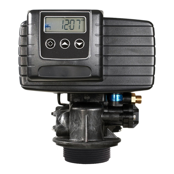
Installer manual Fleck 5600 SXT - Description Components description and location Drive cam Controller LCD screen Regen button Up button Down button Injector block Brine line *Meter Drain line Mixing device Outlet Inlet *Not included in case of timeclock 18 / 104... - Page 19 Installer manual Fleck 5600 SXT - Description Brine cam Motor Brine valve Piston Ref. MKT-IM-013 / E - 23.09.2020 19 / 104...
-
Page 20: System Regeneration Cycle
Installer manual Fleck 5600 SXT - Description System regeneration cycle 3.5.1 Downflow regeneration cycle (5-cycles operation) Service — normal use Untreated water is directed down through the resin bed and up through the riser tube. The hardness ions attach themselves to the resin and are removed from the raw water by being exchanged on the resin beads by sodium ions. - Page 21 Installer manual Fleck 5600 SXT - Description SERVICE NORMAL USE BACKWASH Outlet Inlet Outlet Inlet Drain Valve Valve SECOND BACKWASH BRINE DRAW & SLOW RINSE (Double backwash unit only) Outlet Inlet Outlet Inlet Drain Drain Valve Valve From brine tank...
-
Page 22: Upflow Regeneration Cycle (5-Cycles Operation)
Installer manual Fleck 5600 SXT - Description 3.5.2 Upflow regeneration cycle (5-cycles operation) Service — normal use Untreated water is directed down through the resin bed and up through the riser tube. The hardness ions attach themselves to the resin and are removed from the raw water being exchanged on the resin beads against sodium ions. - Page 23 Installer manual Fleck 5600 SXT - Description SERVICE NORMAL USE BRINE DRAW & SLOW RINSE Outlet Inlet Outlet Inlet Drain Valve Valve From brine tank BACKWASH RAPID RINSE Outlet Inlet Outlet Inlet Drain Drain Valve Valve SERVICE BRINE REFILL NORMAL USE...
-
Page 24: Filter Cycle (3-Cycles Operation)
Installer manual Fleck 5600 SXT - Description 3.5.3 Filter cycle (3-cycles operation) Service — normal use Untreated water is directed down through the filter media and up through the riser tube. The impurities are retained by the media. The water is filtered as it passes through the media. - Page 25 Installer manual Fleck 5600 SXT - Description SERVICE NORMAL USE BACKWASH Outlet Inlet Outlet Inlet Drain Valve Valve SERVICE RAPID RINSE NORMAL USE Outlet Inlet Outlet Inlet Drain Valve Valve Untreated water Ref. MKT-IM-013 / E - 23.09.2020 25 / 104...
-
Page 26: Configurations For Downflow Softener, Upflow Softener And Filter
Installer manual Fleck 5600 SXT - Description Configurations for downflow softener, upflow softener and filter To configure the valve as downflow softener, upflow softener or filter, the valve body, the piston and the cycle cam must be set as shown below. -
Page 27: Upflow Softener
Installer manual Fleck 5600 SXT - Description 3.6.2 Upflow softener Upflow piston P/N 25593 Upflow valve body with mixing P/N 28405-40 Red drive cam P/N 17885 Ref. MKT-IM-013 / E - 23.09.2020 27 / 104... -
Page 28: Filter
Installer manual Fleck 5600 SXT - Description 3.6.3 Filter Downflow piston P/N 27077 Plugged BLFC and injector Downflow valve body without mixing P/N 28405-10 Black single backwash drive cam P/N 17438 28 / 104 Ref. MKT-IM-013 / E - 23.09.2020... -
Page 29: Options Available On The Valve
Installer manual Fleck 5600 SXT - Description Options available on the valve Mixing device The valve can be equipped with a mixing device (1) whose function is to regulate the hardness of the water at the outlet. The mixing can be set from 0% to 50% of hard water (i.e. 0 turn = 0% of hard water with 100% of treated water and 1-½ turn = 50% of hard water with 50% of treated... -
Page 30: System Sizing
Installer manual Fleck 5600 SXT - System sizing System sizing Recommended Injector/DLFC/BLFC-Valve configuration Brine Tank Resin Injector DLFC BLFC syst. Diameter volume [in] Color Color [gpm] DF [gpm] UF [gpm] 5600/ 0000 Black 0.125 0.125 1650 5 - 8 Brown... -
Page 31: Determining The Required Volume Of Resin
Installer manual Fleck 5600 SXT - System sizing Service velocity Inlet water hardness °f °dH [bed volume per hour] [mg/l as CaCO °TH 8 - 40 <350 <35 <19.6 8 - 30 350 to 450 35 - 45 19.6 - 25.2 8 - 20 >450... -
Page 32: Resin Exchange Capacity And Capacity Of The Unit
Installer manual Fleck 5600 SXT - System sizing = Fs × BV with: service max service : service flow rate [m service max : service velocity [BV/h] service BV: bed volume of resin [m Knowing this required volume of resin, it is possible now to determine the needed tank. Note that at least a third of the total volume of the tank must be kept as free space so that the bed expansion during backwash is sufficient to ensure correct cleaning of the resin. -
Page 33: Valve Configuration
Installer manual Fleck 5600 SXT - System sizing Salt amount Corresponding resin °f.m °dH.m [g/L exchange capacity [per L [per L resin resin resin [g/L ] as CaCO resin 53.8 5.38 3.01 55.5 5.55 58.5 5.85 3.27 62.7 6.27 66.9 6.69... -
Page 34: Cycle Time Calculation
Installer manual Fleck 5600 SXT - System sizing regeneration of the unit. From this data, determine the required backwash flow rate as well as the brine draw and slow rinse flow rate. In most cases, the fast rinse flow rate will be the same as the backwash flow rate, however for certain valve types the fast rinse flow rate will be the same as the service flow rate. - Page 35 Installer manual Fleck 5600 SXT - System sizing • the resin volume previously determined; • the salt amount used per regeneration; • the volume of water to use for backwash, brine draw, slow rinse and fast rinse. To calculate the backwash duration: = (N ×...
-
Page 36: Salt Amount Definition
Installer manual Fleck 5600 SXT - System sizing To calculate fast rinse duration: The fast rinse is aimed at eliminating an excess of salt in the resin bed and also recompacting the resin in the tank. Depending on the valve type, the fast rinse flow rate is controlled by the DLFC or it has about the same flow rate as in service. -
Page 37: 1650 Injectors
Installer manual Fleck 5600 SXT - System sizing 4.4.1 1650 injectors INJECTOR 000 Total Rinse Draw Inlet pressure [bar] INJECTOR 00 Total Rinse Draw Inlet pressure [bar] INJECTOR 0 Total Rinse Draw Inlet pressure [bar] Ref. MKT-IM-013 / E - 23.09.2020... - Page 38 Installer manual Fleck 5600 SXT - System sizing INJECTOR 1 Total Rinse Draw Inlet pressure [bar] INJECTOR 2 Total Rinse Draw Inlet pressure [bar] 38 / 104 Ref. MKT-IM-013 / E - 23.09.2020...
-
Page 39: Installation
Installer manual Fleck 5600 SXT - Installation Installation CAUTION Risk of injury due to electrical shock or pressurized elements ! It is strictly forbidden for not qualified personal, to accede to system’s internal parts to perform any kind of technical action. -
Page 40: Water
Installer manual Fleck 5600 SXT - Installation • keep the media tank in an upright position. Do not turn on its side, upside down, or drop it. Turning the tank upside down may cause media to enter the valve or might clog the upper screen;... -
Page 41: Mechanical
Installer manual Fleck 5600 SXT - Installation 5.3.4 Mechanical Caution - material Risk of damage due to wrong lubricant use ! Do not use petroleum-based lubricants such as vaseline, oils, or hydrocarbon-based lubricants. Use only approved silicone grease or soapy water ! •... -
Page 42: Valve Connection To Piping
Installer manual Fleck 5600 SXT - Installation Valve connection to piping The connections should be hand tightened using PTFE (plumber’s tape) on the threads if using the threaded connection type. In case of heat welding (metal type connection), the connections should not be made to the valve when soldering. - Page 43 Installer manual Fleck 5600 SXT - Installation • failure to provide enough vertical compensation may lead to different kinds of damage, either on the valve thread which is connected to the tank, or on the female thread connection of the tank.
-
Page 44: Block Diagram And Configuration Example
Installer manual Fleck 5600 SXT - Installation Block diagram and configuration example Block diagram Pressure gauge Main inlet User’s line Check valve to prevent water harm Filter cartridge By-pass Pressure regulator Meter Suggested options Mixing device Can be integrated in the... -
Page 45: Regeneration Flows
Installer manual Fleck 5600 SXT - Installation Regeneration flows Metered immediate control A meter immediate control measures water usage and regenerates the system as soon as the calculated system capacity is depleted. The control calculates the system capacity by dividing the unit capacity (typically expressed in °TH*m... -
Page 46: Electrical Connections
Installer manual Fleck 5600 SXT - Installation Electrical connections 5.8.1 Downflow configuration W1: Black W2: Red W3: Green W4: Yellow W5: White W6: Blue W7: Orange W8: Violet Transformer Info The microswitch SW2 is connected on C and NC. 46 / 104... -
Page 47: Upflow Configuration
Installer manual Fleck 5600 SXT - Installation 5.8.2 Upflow configuration W1: Black W2: Red W3: Green W4: Yellow W5: White W6: Blue W7: Orange W8: Violet Transformer Info The microswitch SW2 is connected on C and NO. Ref. MKT-IM-013 / E - 23.09.2020... -
Page 48: Bypassing
Installer manual Fleck 5600 SXT - Installation Bypassing A bypass valve system should be installed on all water conditioning systems. Bypass valves isolate the softener from the water system and allow unconditioned water to be used. Service or routine maintenance procedures may also require that the system is bypassed. - Page 49 Installer manual Fleck 5600 SXT - Installation Caution - material Risk of damage due to over-force ! The drain line plastic elbow must always be hand-tighten without using the elbow as a lever. The drain plastic elbow is not designed to support the weight of the tube. The tube has to have its own support.
-
Page 50: Overflow Line Connection
Installer manual Fleck 5600 SXT - Installation Air gap Drain 5.11 Overflow line connection In the event of a malfunction, the brine tank overflow fitting will direct “overflow” to the drain instead of spilling on the floor. This fitting should be on the side of the brine tank. Most brine tank manufacturers feature a pre-drilled hole for the tank overflow connector. -
Page 51: Brine Line Connection
Installer manual Fleck 5600 SXT - Installation 5.12 Brine line connection Mandatory The brine line must be built with 3/8'' semi rigid piping ! Caution - material Risk of malfunction due to the use of wrong equipment ! Flexible and semi-flexible hoses may shrink because of the vacuum during brine draw. -
Page 52: Programming
Installer manual Fleck 5600 SXT - Programming Programming Display 1. Service icon • Appears in service mode; • Flashes if a regeneration cycle has been queued. 2. Error / • Appears in case of error, see Troubleshooting [ → Page 87], or in Information icon diagnostic mode, see.Diagnostic [... - Page 53 Installer manual Fleck 5600 SXT - Programming 3. Parameter Master programming and diagnostic modes: display • C: Unit capacity; • CD: Current day; • CT: Regeneration control type; • DF: Display format; • Dn, n=1 to 7: Day of week;...
-
Page 54: Commands
Installer manual Fleck 5600 SXT - Programming 8. Programming • Appears in programming modes. icon Commands Info Menus are displayed in a defined and incremental order. If none of the buttons are pushed for 5 minutes in the Programming mode, or if there is a power failure, the controller returns to Service mode without saving. -
Page 55: Day Of Override (Do)
Installer manual Fleck 5600 SXT - Programming 6.4.2 Day of override (DO) 1. Press simultaneously for 5 seconds to enter the menus sequence. 2. Select the number of days of override with 3. Press to validate the selection and advance to the next parameter. -
Page 56: Master Programming Mode Chart
Installer manual Fleck 5600 SXT - Programming 6.5.1 Master programming mode chart Parameter Options Definition Note Display format US units Metric units Regeneration dF1b Std DF single Standard for 9000 Twin valve flow backwash dF2b Std DF double backwash FLtr Filter To be used with standard piston only. - Page 57 Installer manual Fleck 5600 SXT - Programming Parameter Options Definition Note Fixed reserve 0 to 50 Only displayed for volumetric capacity regenerations and if set in reserve selection. Days override 0 to 99 Regeneration 00:00:00 to Hour Regeneration time will not appear...
-
Page 58: Entering Master Programming Mode
Installer manual Fleck 5600 SXT - Programming 6.5.2 Entering master programming mode 1. Press and hold until the programming icon replaces the service icon and the parameter display reads TD. 2. Set the time to 12:01 PM with 3. Press to validate the selection and return to the service mode, or wait for 10 seconds. -
Page 59: Number Of Tanks (Nt)
Installer manual Fleck 5600 SXT - Programming 1. Press to select the regeneration control type. 2. Press to validate the selection and move to the next parameter. 6.5.6 Number of tanks (NT) Select the number of tanks. Options: • NT 1: single tank system;... -
Page 60: Feedwater Hardness (H)
Installer manual Fleck 5600 SXT - Programming Info The filter capacity parameter is only available if the regeneration flow has been programmed for filter. The filter capacity can be set from 0.1 to 9’999 x1’000 Ltr if DF = Ltr or from 1 to 9’999 -> 1 to 9’999 x1’000 grains if DF = GAL. -
Page 61: Days Override (Do)
Installer manual Fleck 5600 SXT - Programming 6.5.11.2 Reserve capacity (RC) Info This parameter is not shown if RS is set to SF. The fixed reserve capacity can be set up to a volume equivalent to 50% of the initial volumetric capacity. -
Page 62: Day Of Week (Dn, N = 1 To 7)
Installer manual Fleck 5600 SXT - Programming Info Setting a cycle step to 0 will cause the controller to skip that step during regeneration, but keeps the following steps available. The different regeneration cycles are listed in sequence based on the regeneration flow selected for the system. -
Page 63: Meter Pulse (K)
Installer manual Fleck 5600 SXT - Programming Options: • P0.7: ¾" paddle wheel meter (Standard setting for 4600, 5600 and 9100); • t0.7: ¾" turbine meter; • P1.0: 1" paddle wheel meter (Standard setting for 2750 and 9000); • t1.0: 1" turbine meter;... -
Page 64: Current Flow Rate (Fr)
Installer manual Fleck 5600 SXT - Programming 6.7.2 Current flow rate (FR) Info The display is updated every second. 1. Current flow rate display (L/min or gpm depending on display format programmed): 6.7.3 Peak flow rate (PF) Info The controller registers the highest flow rate (L/min) since the last regeneration. -
Page 65: Software Version (Sv)
Installer manual Fleck 5600 SXT - Programming 6.7.7 Software version (SV) Info Shows the version of the software used by the controller. 1. Software version display: Resetting the controller Mandatory Once you have completed this operation, check all programming steps ! Info There are two options to reset: partial and hard reset. -
Page 66: Commissioning
Installer manual Fleck 5600 SXT - Commissioning Commissioning Info This chapter is available for standard regeneration flows. Contact your supplier if the actual regeneration is not standard and if you need assistance. Water filling, draining and waterproofness inspection 1. With the bypass still in bypass position (inlet and outlet of the valve closed), plug in the SXT controller to the power source. -
Page 67: Sanitization
Installer manual Fleck 5600 SXT - Commissioning The system is ready and in service. Sanitization 7.2.1 Disinfection of water softeners The materials of construction of the modern water softener will not support bacterial growth, nor will these materials contaminate a water supply. In addition, during normal use, a softener may become polluted with organic matter, or in some cases with bacteria from the water supply. -
Page 68: Electro Chlorination
Installer manual Fleck 5600 SXT - Commissioning 7.2.3 Electro chlorination Valves or systems already equipped with an electrochlorinator device or system will be sanitized during the brine draw phase. 68 / 104 Ref. MKT-IM-013 / E - 23.09.2020... -
Page 69: Operation
Installer manual Fleck 5600 SXT - Operation Operation Display 8.1.1 Display during operation Examples: • Valve in service with day time: • Valve in service with volume remaining before regeneration: • Remaining days before next regeneration: • In volumetric regeneration flow, reserve 1223 litres remaining: •... -
Page 70: Recommendations
Installer manual Fleck 5600 SXT - Operation Recommendations • Use only regeneration salts designed for water softening in accordance with EN973; • for optimal system operation, the use of clean salt, free from impurities, is recommended (for example salt pellets);... -
Page 71: Operation During A Power Failure
Installer manual Fleck 5600 SXT - Operation Operation during a power failure • Current valve position, cycle step time elapsed, and time of day is stored 24 hours during a power failure, and will be restored upon power restoration; • in regeneration, when power is shutting down, the controller saves the current regeneration data. -
Page 72: Maintenance
Installer manual Fleck 5600 SXT - Maintenance Maintenance Mandatory Cleaning, maintenance and service operation shall take place at regular intervals and must be done by qualified personnel only in order to guarantee the proper functioning of the complete system. Report maintenance done in the Maintenance chapter of the User Guide document. -
Page 73: Regeneration Test
Installer manual Fleck 5600 SXT - Maintenance 9.1.3 Regeneration test 9.1.3.1 Valve used for softening 1. Check condition of brine tank and any associated equipment. 2. Check salt level in brine tank. 3. Initiate regeneration test. ð Check brine draw during brine draw stage. -
Page 74: Recommended Maintenance Plan
Installer manual Fleck 5600 SXT - Maintenance Recommended maintenance plan 9.2.1 Valve used for softening Items 1 year 2 year 3 year 4 year 5 year Injector & filter Clean Clean Clean Clean Clean/ replace if necessary BLFC*** Clean Clean... - Page 75 Installer manual Fleck 5600 SXT - Maintenance Items 1 year 2 year 3 year 4 year 5 year Valve Check Check Check Check Check watertightness Valve to piping Check Check Check Check Check watertightness * Wear parts - durability strongly affected by raw water quality and regeneration frequency.
-
Page 76: Valve Used For Filtration
Installer manual Fleck 5600 SXT - Maintenance 9.2.2 Valve used for filtration Items 1 year 2 year 3 year 4 year 5 year DLFC*** Clean Clean Clean Clean Clean/ replace if necessary Bypass (if Clean Clean Clean Clean Clean/replace present,... -
Page 77: Recommendations
Installer manual Fleck 5600 SXT - Maintenance Recommendations 9.3.1 Use original spare parts Caution - material Risk of damage due to use of non-genuine spare parts ! To ensure correct operation and safety of the device, only use original spare parts and accessories recommended by the manufacturer. -
Page 78: Controller Motor Replacement
Installer manual Fleck 5600 SXT - Maintenance 9.4.2 Controller motor replacement 1. Using a flat screwdriver, unscrew (4) and remove the cover (3). 2. Disconnect the motor (1). 3. Using a Philips screwdriver, unscrew (2) and remove the motor (1). -
Page 79: Controller Replacement
Installer manual Fleck 5600 SXT - Maintenance 9.4.3 Controller replacement 1. Using a Philips screwdriver, unscrew (1) and remove the cover (2) paying attention for the wire. 2. Press the board clips (3) and release the controller cover (6). 3. Using a flat screwdriver, unscrew (5) and remove the controller (4). -
Page 80: Piston And/Or Brine Valve And/Or Seal And Spacer Kit Replacement
Installer manual Fleck 5600 SXT - Maintenance 9.4.4 Piston and/or brine valve and/or seal and spacer kit replacement 1. Remove the power head, see Power head disassembly/replacement. 2. Using a flat screwdriver or an 8 mm wrench, unscrew (3) and remove the top plate (4). - Page 81 Installer manual Fleck 5600 SXT - Maintenance Item Part number Description Packaging quantity 12763 Stuffer Ref. MKT-IM-013 / E - 23.09.2020 81 / 104...
-
Page 82: Microswitches And/Or Drive Cam Replacement
Installer manual Fleck 5600 SXT - Maintenance 9.4.5 Microswitches and/or drive cam replacement 1. Using a Philips screwdriver, unscrew (1) and remove the cover (2). 2. Disconnect the wire on the microswitches (6). 3. Using a Philips screwdriver, unscrew (8). 4. Remove the protection plate (7) and the micorswitches (6). -
Page 83: Brine Cam Replacement
Installer manual Fleck 5600 SXT - Maintenance 9.4.6 Brine cam replacement 1. Remove the power head, see Power head disassembly/replacement. 2. Using a flat screwdriver, unscrew (1). 3. Remove the washer (2) and the brine cam (3). 4. Change the brine cam (3). -
Page 84: Injector Cleaning
Installer manual Fleck 5600 SXT - Maintenance 9.4.7 Injector cleaning 1. Using a flat screwdriver or an 8 mm wrench, remove the screws (6). 2. Remove the cap injector (5). 3. Remove the seal (4). 4. Remove the filter (2). -
Page 85: Blfc Cleaning
Installer manual Fleck 5600 SXT - Maintenance 9.4.8 BLFC cleaning 1. Using a wrench, remove the BLFC holder (1). 2. Using pliers, remove the cage (4) form the BLCF holder (1). 3. Remove the BLFC washer (3) from the BLFC holder (1). 4. Clean the BLFC washer (3) with a terry cloth. -
Page 86: Valve On Tank Assembly
Installer manual Fleck 5600 SXT - Maintenance 9.4.9 Valve on tank assembly 1. Lubricate the seals with approved silicone grease. 2. Spin the valve (1) onto the tank (2), ensuring the threads are not cross-threaded. 3. Rotate the valve (1) clockwise and freely, without using force until it comes to a stop. -
Page 87: Troubleshooting
Installer manual Fleck 5600 SXT - Troubleshooting Troubleshooting Problem Cause Solution Softener fails to Interrupted power or switched off Restore the controller and regenerate automatically power source. connect to constant power source. Disconnected/faulty meter cable. Check connections in the power head and on the meter cover. - Page 88 Installer manual Fleck 5600 SXT - Troubleshooting Problem Cause Solution Resin loss through drain Top distributor missing or broken. Add or replace the top distributor. line Air in water system. Ensure the presence of air check system in the brine tank.
- Page 89 Installer manual Fleck 5600 SXT - Troubleshooting Problem Cause Solution Softener fails to draw Plugged drain line flow control. Clean drain line flow control. brine Plugged injector and/or filter. Clean or replace injector and/or filter. Low water pressure. Raise inlet pressure to 1.8 bar minimum.
-
Page 90: Error Detection
Installer manual Fleck 5600 SXT - Troubleshooting 10.1 Error detection Errors codes appear on the service display. Info It can take up to 1 minute before an error can be detected and displayed. 10.1.1 Motor stall/cam sense error Info The valve drive takes more than 6 minutes to go to the next regeneration cycle and the board hasn’t received expected signals from microswitches. -
Page 91: Motor Run-On Error/Cycle Sense Error
Installer manual Fleck 5600 SXT - Troubleshooting 10.1.2 Motor run-ON error/cycle sense error Info The valve performed an unforeseen cycle. This error message is only valid until controller version 2.6. 1. Unplug the unit and plug back in. Allow the controller to attempt to find position again. -
Page 92: Memory Error
Installer manual Fleck 5600 SXT - Troubleshooting 10.1.4 Memory error Info The controller board has a memory failure. 1. Perform a master reset. 2. Reconfigure the system via master programming mode. 3. Step the valve through a manual regeneration. 4. If the error reoccurs, unplug the unit. -
Page 93: Spare Parts And Options
Installer manual Fleck 5600 SXT - Spare parts and options Spare parts and options 11.1 Valve parts list Item Part number Description Packaging quantity 29100 End plug retainer kit 5600 24116-US Piston assy 4600/5600 Ref. MKT-IM-013 / E - 23.09.2020... - Page 94 Installer manual Fleck 5600 SXT - Spare parts and options Item Part number Description Packaging quantity 24117-US Piston assy 4600/5600 LWU 27077-US Piston assy 4600SXT/5600SXT/6600/6700 DF 18928 Piston assy 4600/5600 Filter 24115 S&S Kit residential 24509-01 Mixing assy residential 29101...
-
Page 95: Power Head Parts List
Installer manual Fleck 5600 SXT - Spare parts and options 11.2 Power head parts list Item Part number Description Packaging quantity PH56SXT-003 PH 4600/5600 SXT Eco PH56SXT-004 PH 4600/5600 SXT Eco UF 25329 Drive Motor assy 24V/50-60Hz 29131 Kit back cover black 4600/5600/6600... -
Page 96: Safety Brine Valves List
Installer manual Fleck 5600 SXT - Spare parts and options Item Part number Description Packaging quantity BU28723 Front panel & label SXT 40422SP Wire Nut Tan 19791-01SP Turbine Meter Cable elec 0.450 m BR43346-E0 Circuit board SXT programmed eco 11.3... -
Page 97: Safety Brine Valves 2310 Parts List
Installer manual Fleck 5600 SXT - Spare parts and options 11.4 Safety brine valves 2310 parts list Item Part number Description Packaging quantity 60014SP Body Assy SBV 2310 18312SP Retainer, drain 19805SP Nut SBV 2310 Plastic 60068-30SP New Float assy 2310... -
Page 98: 1" Bsp Female Brass Bypass With Mixing
Installer manual Fleck 5600 SXT - Spare parts and options Item Part number Description Packaging quantity BU28502 Bypass 1” BSP Female Stainless Steel 13709 Coupling Assy residential 29104 Kit mounting/adapter 2 clips & 2 screws residential 11.5.2 1" BSP female brass bypass with mixing... -
Page 99: Plastic Bypass (No Yoke)
Installer manual Fleck 5600 SXT - Spare parts and options Item Part number Description Packaging quantity 24509-02 Mixing assy 4600 Hot Water 11.5.3 Plastic bypass (no yoke) Item Part number Description Packaging quantity BU26054 Bypass plastic 29104 Kit mounting/adpater 2 clips & 2 screws... -
Page 100: Distribution Systems Parts List
Installer manual Fleck 5600 SXT - Spare parts and options 11.6 Distribution systems parts list Item Part number Description Packaging quantity 27827 Distributor assy, 1” high flow 1 m 10 25645 Distributor assy, 1” high flow 1 m 95 BU28508 Distributor assy, 1”... -
Page 101: Air Checks List
Installer manual Fleck 5600 SXT - Spare parts and options 11.7 Air checks list Item Brine Part Description Packaging system number quantity 1600 18168 Air checks 500A, 915mm (36") 26773 Air checks 500A, 1m25 23473 Air checks 500 HW 11.8... - Page 102 Installer manual Fleck 5600 SXT - Spare parts and options 11.9 CE compliance parts list Item Part number Description Packaging quantity 18280SP Top distributor 1” grey 18280-01SP Top distributor 1” wide slots natural 18280-02SP Top distributor 1” narrow slots red...
- Page 103 This will help to reduce the impact on the environment, health, safety and help to promote recycling. Pentair do not collect used product for recycling. Contact your local recycling center for more information.
- Page 104 All indicated Pentair trademarks and logos are property of Pentair. Third party registered and unregistered trademarks and logos are the property of their respective owners. © 2020 Pentair. All rights reserved.