Pentair FLECK 5800 SXT Installer Manual
Hide thumbs
Also See for FLECK 5800 SXT:
- User manual (37 pages) ,
- Service manual (24 pages) ,
- Installation (3 pages)
Table of Contents
Advertisement
Quick Links
Advertisement
Table of Contents

Related Manuals for Pentair FLECK 5800 SXT


Summary of Contents for Pentair FLECK 5800 SXT
- Page 1 FLECK 5800 SXT...
-
Page 2: Table Of Contents
Installer Manual Fleck 5800 - SXT - Table of content Table of content Generalities ......... . 7 1.1. - Page 3 Installer Manual Fleck 5800 - SXT - Table of content System sizing ........25 4.1.
- Page 4 Installer Manual Fleck 5800 - SXT - Table of content 6.4.1. Day of Override (DO) ......... 47 6.4.2.
- Page 5 Installer Manual Fleck 5800 - SXT - Table of content Commissioning ........64 7.1.
- Page 6 Installer Manual Fleck 5800 - SXT - Table of content Troubleshooting ........77 10.1.
-
Page 7: Generalities
Author Description 18.04.2017 First edition 1.3. Manufacturer identifier, product Manufacturer: Pentair Manufacturing Italy Srl Via Masaccio, 13 56010 Lugnano di Vicopisano (PI) – Italy Product: Fleck 5800 - SXT 1.4. Intended use The device is intended to be used for domestic applications only and it is purpose-built for water treatment. -
Page 8: Abbreviations Used
Installer Manual Fleck 5800 - SXT - Generalities 1.5. Abbreviations used DF............Down Flow UF............Up Flow HW............Hot Water Inj ............Injector DLFC ............Drain Line Flow Controller BLFC / Refill Flow Controller....Brine Line Flow Controller QC............Quick Connect Regen ............ -
Page 9: Procedure For Technical Support
Pentair Quality System EMEA products benefit, under specific conditions, from a manufacturer warranty that may be invoked by Pentair’s direct customers. Users should contact the vendor of this product for applicable conditions and in case of a potential warranty claim. -
Page 10: Safety
Installer Manual Fleck 5800 - SXT - Safety Safety 2.1. Safety pictograms definition Caution Warning Warns of a risk of minor injury or major Warns against serious personal injury material damage to the device or and damage to health. environment. Danger... -
Page 11: Personnel
Installer Manual Fleck 5800 - SXT - Safety 2.3.1. Personnel Only qualified and professional personnel, based on their training, experience and instruction as well as their knowledge of the regulations, the safety rules and operations performed, are authorized to carry out necessary work. 2.3.2. -
Page 12: Description
Installer Manual Fleck 5800 - SXT - Description Description 3.1. Technical specifications Design specifications/ratings Valve body ..........Fiber-reinforced polymer Rubber components ....... EP / EPDM / Silicon Valve material certification ....DM174, ACS, CE Weight (valve with controller) ....2 kg (max) Recommended operating pressure .. -
Page 13: Performance Flow Rate Characteristics
Installer Manual Fleck 5800 - SXT - Description Environmental conditions • Indoor use only; • Temperature from 5°C to 40°C; • Maximum relative humidity 80% for temperatures up to 31°C decreasing linearly to 50% relative humidity at 40°C; • Mains supply voltage fluctuations up to ±10% of the nominal voltage. 3.1.1. -
Page 14: Outline Drawing
Installer Manual Fleck 5800 - SXT - Description 3.2. Outline drawing 14 / 92 Ref. MKT-IM-004 / A - 18.04.2017... -
Page 15: Description And Components Location
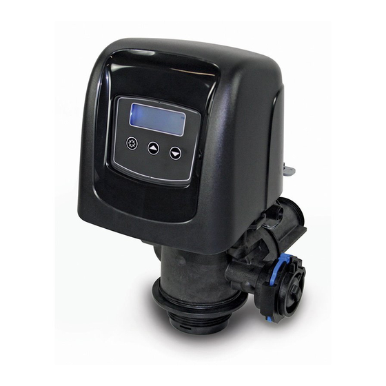
Installer Manual Fleck 5800 - SXT - Description 3.3. Description and components location Controller LCD screen Regen button Up button Down button Brine line Injector block Drain line Outlet Mixing device Inlet *Meter Piston Brine valve *Not included in case of timeclock Ref. -
Page 16: System Regeneration Cycle
Installer Manual Fleck 5800 - SXT - Description 3.4. System regeneration cycle Note This valve allows to do down flow or up flow regenerations. 3.4.1. Downflow regeneration cycle (5-cycles operation) Service — normal use Untreated water is directed down through the resin bed and up through the riser tube. The hardness ions attach themselves to the resin and are removed from the raw water being exchanged on the resin beads against sodium ions. - Page 17 Installer Manual Fleck 5800 - SXT - Description Note For illustration purpose only. Always verify inlet and outlet marking on the valve. SERVICE NORMAL USE BACKWASH Outlet Inlet Outlet Inlet Drain Valve Valve BRINE DRAW & SLOW RINSE RAPID RINSE Outlet Inlet Outlet...
-
Page 18: Upflow Regeneration Cycle (5-Cycles Operation)
Installer Manual Fleck 5800 - SXT - Description 3.4.2. Upflow regeneration cycle (5-cycles operation) Service — normal use Untreated water is directed down through the resin bed and up through the riser tube. The hardness ions attach themselves to the resin and are removed from the raw water being exchanged on the resin beads against sodium ions. - Page 19 Installer Manual Fleck 5800 - SXT - Description Note For illustration purpose only. Always check for inlet and outlet marking on the valve. SERVICE NORMAL USE BRINE DRAW & SLOW RINSE Outlet Inlet Outlet Inlet Drain Valve Valve From brine tank BACKWASH RAPID RINSE...
-
Page 20: Upflow Fill First Regeneration Cycle (5-Cycles Operation)
Installer Manual Fleck 5800 - SXT - Description 3.4.3. Upflow fill first regeneration cycle (5-cycles operation) Service — normal use Untreated water is directed down through the resin bed and up through the riser tube. The hardness ions attach themselves to the resin and are removed from the raw water being exchanged on the resin beads against sodium ions. - Page 21 Installer Manual Fleck 5800 - SXT - Description Note For illustration purpose only. Always check for inlet and outlet marking on the valve. SERVICE NORMAL USE BRINE REFIL Inlet Outlet Inlet Outlet Valve Valve To brine tank BRINE DRAW & SLOW RINSE BACKWASH Inlet Outlet...
-
Page 22: Filter Cycle (3-Cycles Operation)
Installer Manual Fleck 5800 - SXT - Description 3.4.4. Filter cycle (3-cycles operation) Service — normal use Untreated water is directed down through the media and up through the riser tube. The impurities are retained by the media. The water is filtered as it passes through the media. Backwash —... -
Page 23: Configurations For Downflow Softener, Upflow Softener And Filter
Installer Manual Fleck 5800 - SXT - Description 3.5. Configurations for downflow softener, upflow softener and filter 3.5.1. Downflow softener The injector is in the upper hole and the plug in the lower hole. 3.5.2. Upflow softener The injector is in the lower hole and the plug in the upper hole. Note... -
Page 24: Options Available On The Valve
Installer Manual Fleck 5800 - SXT - Description 3.6. Options available on the valve Mixing device The valve can be equipped with a mixing device (1) whose function is to regulate the hardness of the water at the outlet. The mixing can be set from 0% to 50% of hard water (i.e. 0 turn = 0% of hard water with 100% of treated water and 1-½... -
Page 25: System Sizing
Installer Manual Fleck 5800 - SXT - System sizing System sizing 4.1. Recommendations 4.1.1. Injector/DLFC/BLFC-Valve configuration Tank Resin Injector DLFC BLFC Valve diameter volume type [in] Color Color [gpm] DF [gpm] UF [gpm] 0000 Black 5 - 7 0.125 Brown 8 - 14 0.125 9 - 21... - Page 26 Installer Manual Fleck 5800 - SXT - System sizing The softening and regeneration reactions are driven under certain conditions. To allow these reactions to take place, make sure that the velocity is convenient during the different phases for proper ion exchange. This velocity is given in the resin manufacturer specifications sheet. Depending on the inlet water hardness, the service velocity for standard softening must be between: Inlet water hardness Service velocity...
-
Page 27: Determining The Required Volume Of Resin
Installer Manual Fleck 5800 - SXT - System sizing 4.2.2. Determining the required volume of resin When sizing a softener, make sure that the volume of resin in the tank (bed volume) will be sufficient so that even when the peak flow rate is reached, the velocity is still between the above values depending on the hardness. - Page 28 Installer Manual Fleck 5800 - SXT - System sizing Resin exchange capacity as a function of the salt dosage: Salt amount Corresponding resin exchange °f.m °dH.m [g/L capacity in [g/L ] as CaCO [per L [per L resin resin resin resin 29.9 2.99...
-
Page 29: Valve Configuration
Installer Manual Fleck 5800 - SXT - System sizing To calculate the system volume capacity: / TH with: capacity capacity inlet : system volume capacity [m capacity : system mass capacity [kg as CaCO ] or [°f.m or °dH.m capacity : system combined capacity [°f.m or °dH.m capacity... -
Page 30: Cycle Time Calculation
Installer Manual Fleck 5800 - SXT - System sizing To determine the injector size: The velocities to be respected for brine draw and slow rinse are given on the resin manufacturer specifications. Generally speaking, the injector has to allow a flow rate of about 4BV / h (corresponding to the flow rate of brine being drawn added to the flow rate of raw water passing through the injector nozzle to create the suction effect). - Page 31 Installer Manual Fleck 5800 - SXT - System sizing To calculate the brine draw duration: Knowing the injector flow rate at the working pressure: brine draw brine with: : brine draw duration [min] brine draw : brine volume to be drawn [L] see Refill calculation brine page 32 : injection draw flow rate [L/min]...
-
Page 32: Salt Amount Definition
Installer Manual Fleck 5800 - SXT - System sizing To calculate the refill duration: The refill flow rate is controlled by the refill controller (BLFC). The relation between the BLFC size, the tank size and the resin volume is given in the valve specifications. To calculate the refill duration: refill BLFC... -
Page 33: 1650 Injector Flow Rates
Installer Manual Fleck 5800 - SXT - System sizing 4.4. 1650 Injector flow rates The following tables and graphics represent the injectors flow rate as a function of the inlet pressure for the different injector sizes. INJECTOR 000 Total Rinse Draw Inlet pressure [bar] INJECTOR 00... - Page 34 Installer Manual Fleck 5800 - SXT - System sizing INJECTOR 0 Total Rinse Draw Inlet pressure [bar] INJECTOR 1 Total Rinse Draw Inlet pressure [bar] INJECTOR 2 Total Rinse Draw Inlet pressure [bar] 34 / 92 Ref. MKT-IM-004 / A - 18.04.2017...
- Page 35 Installer Manual Fleck 5800 - SXT - System sizing INJECTOR 3 Total Rinse Draw Inlet pressure [bar] INJECTOR 4 Total Rinse Draw Inlet pressure [bar] INJECTOR 5 Total Rinse Draw Inlet pressure [bar] Ref. MKT-IM-004 / A - 18.04.2017 35 / 92...
-
Page 36: Installation
Installer Manual Fleck 5800 - SXT - Installation Installation Mandatory It is strictly forbidden for not qualified personal, to accede to system’s internal parts to perform any kind of technical action. Be sure to disconnect the electrical power, close the water inlet and depressurize the system before opening the front cover to access internal parts. -
Page 37: Water
Installer Manual Fleck 5800 - SXT - Installation 5.3.2. Water • Water temperature must not exceed 43°C. • A minimum of 1.4 bar (dynamic pressure on injector) of water pressure is required for the regeneration valve to operate effectively. Mandatory Do not exceed a maximum of 8.6 bar inlet pressure. -
Page 38: Integration Constraints
Installer Manual Fleck 5800 - SXT - Installation • It is not recommended to use sealants on the threads. Use PTFE (plumber’s tape) on the threads of the drain elbow, and other NPT/BSP threads. • The installation of a prefilter is always recommended (100μ nominal). •... -
Page 39: Top-Mounted Valve Installation
Installer Manual Fleck 5800 - SXT - Installation 5.5.1. Top-mounted valve installation When pressurized, any composite tank will expand both vertically and circumferential. In order to compensate the vertical expansion, the piping connections to the valve must be flexible enough to avoid overstress on the valve and tank. - Page 40 • In any case, any failure caused by improper installation and/or piping connections may void the warranty of Pentair products. • In the same way, using lubricant* on the valve thread is not allowed and will void the warranty for the valve and tank.
-
Page 41: Block Diagram And Configuration Example
Installer Manual Fleck 5800 - SXT - Installation 5.6. Block diagram and configuration example Configuration example V580SC-001 27833 21675 18168 Block diagram By-pass Main inlet Gauge Gauge User’s line Check valve to prevent water hammer and eventual hot water returns. Turbine Mixing Drain... -
Page 42: Regeneration Types
Installer Manual Fleck 5800 - SXT - Installation 5.7. Regeneration types Metered: The controller monitors the volume of water used. Once it calculates that there is not enough capacity for the next days operation, a regeneration cycle will be initiated immediately or at a pre-set time. •... -
Page 43: By-Passing
Installer Manual Fleck 5800 - SXT - Installation 5.9. By-passing A bypass valve system should be installed on all water conditioning systems. Bypass valves isolate the softener from the water system and allow unconditioned water to be used. Service or routine maintenance procedures may also require that the system is bypassed. -
Page 44: Drain Line Connection
Installer Manual Fleck 5800 - SXT - Installation 5.10. Drain line connection Note Standard commercial practices are expressed here. Local codes may require changes to the following suggestions. Check with local authorities before installing a system. Preferably, the unit should not be more than 6.1 m from the drain. Use an appropriate adapter fitting to connect plastic tubing to the drain line connection of the valve. -
Page 45: Overflow Line Connection
Installer Manual Fleck 5800 - SXT - Installation 5.11. Overflow line connection In the event of a malfunction, power failure, etc, the brine tank overflow fitting will direct “overflow” to the drain instead of spilling on the floor. This fitting should be on the side of the cabinet or brine tank. -
Page 46: Programming
Installer Manual Fleck 5800 - SXT - Programming Programming 6.1. Display 1. Parameter display → C: Unit capacity; → CD: Current day; → Cn, n=1 to 20: Cycle number; → CR: Variable reserve capacity; → CT: Regeneration control type; ... -
Page 47: Commands
Installer Manual Fleck 5800 - SXT - Programming 2. Data display 3. PM indicator → Appears if controller set in US unit. 4. Flow indicator → Flashes when outlet flow is detected. 5. x1000 indicator → Appears when the displayed number is bigger than 9999. 6. -
Page 48: Regeneration Time (Rt)
Installer Manual Fleck 5800 - SXT - Programming 6.4.2. Regeneration time (RT) Determine the time of regeneration. Adjust the regeneration time with Press to validate the selection and advance to the next parameter. 6.4.3. Feed Water Hardness (H) Determine the feed water hardness in °tH. Adjust the water hardness with Press to validate the selection and advance to the next parameter. -
Page 49: Master Programming Mode
Installer Manual Fleck 5800 - SXT - Programming 6.5. Master programming mode Note As soon as programming mode is entered, all parameters can be displayed or set to suit the needs. Depending on the current programming, some functions will not be displayed or will not be changeable. - Page 50 Installer Manual Fleck 5800 - SXT - Programming Parameter Options Definition Note Meter delayed Meter immediate Regeneration control type Time clock Day of the week 0.1 to Only displayed for volumetric Unit capacity °TH*m 9’999’000 regenerations. Filter capacity 1 to 999’900 Only displayed for filter.
- Page 51 Installer Manual Fleck 5800 - SXT - Programming Parameter Options Definition Note BD, BW, RF, Cycle number, RR, SP, SR, Only displayed for O-dF and O-UF. n=1 to 20 Day of week, Regeneration setting for each day of On - OFF n=1 to 7 the week.
-
Page 52: Entering Master Programming Mode
Installer Manual Fleck 5800 - SXT - Programming 6.5.2. Entering master programming mode Press and hold until the programming icon replaces the service icon and the parameter display reads TD. Set the time to 12:01 PM with Press to validate the selection and return to the service mode, or wait for 10 seconds. -
Page 53: Regeneration Control Type (Ct)
Installer Manual Fleck 5800 - SXT - Programming Press to select the regeneration flow. Press to validate the selection and move to the next parameter. 6.5.6. Regeneration control type (CT) Select the controller type. Options: • Fd: Meter delayed; • FI: Meter immediate;... -
Page 54: Feedwater Hardness (H)
Installer Manual Fleck 5800 - SXT - Programming 6.5.9. Feedwater hardness (H) Set the feedwater hardness. Note The feedwater hardness parameter is only available if the controller type has been programmed for volumetric regeneration. Mandatory Enter the feedwater hardness in °TH, ppm or grains of hardness for softener system. Note... -
Page 55: Days Override (Do)
Installer Manual Fleck 5800 - SXT - Programming Press to set the safety factor. Press to validate the selection and move to the next parameter. 6.5.10.2 Fixed reserve capacity (RC) Set the reserve capacity. Note The fixed reserve capacity parameter is only available if this option has been set in reserve selection. -
Page 56: Regeneration Time (Rt)
Installer Manual Fleck 5800 - SXT - Programming 6.5.12. Regeneration time (RT) Set the regeneration time. Note Regeneration time is the time of the day when regenerations occur for delayed regeneration of any type and calendar override regeneration. AA Press to set the regeneration time. -
Page 57: Day Of Week (Dn, N = 1 To 7)
Installer Manual Fleck 5800 - SXT - Programming 6.5.13.3 For regeneration type O-UF and O-DF Note The regeneration cycles are identified as C1 to C20. Mandatory The last cycle must be set with LC. AE Press to set the type of regeneration cycle. AF Press to validate the selection. -
Page 58: Flow Meter Type (Fm)
Installer Manual Fleck 5800 - SXT - Programming 6.5.16. Flow meter type (FM) Select the flow meter type. Options: • P0.7: ¾" paddle wheel meter; • t0.7: ¾" turbine meter (Standard setting for 5800 SXT); • P1.0: 1" paddle wheel meter; •... -
Page 59: Flow Based Relay Setting (Vr)
Installer Manual Fleck 5800 - SXT - Programming 6.5.18.1 Relay start time (ST) Set the relay start time. Note This option is available only if RE is set to tb. Note The relay start time can be set from 0 minute to the total of time of all the cycles minus 1 minute. -
Page 60: Filter Programming
Installer Manual Fleck 5800 - SXT - Programming 6.5.19.1 Relay volume interval (VO) Set the relay volume interval. Note This option is available only if VR is set to Fb. Note The relay volume interval can be set from 1 to the total capacity in litres. BD Press to set the relay volume interval. -
Page 61: Diagnostic
Installer Manual Fleck 5800 - SXT - Programming 6.7. Diagnostic Note Depending on current settings, some displays cannot be viewed. Note If none of the buttons are pushed for 1 minute in the diagnostic mode the controller returns to Service mode. 6.7.1. -
Page 62: Volume Since Last Regeneration (Vu)
Installer Manual Fleck 5800 - SXT - Programming 6.7.5. Volume since last regeneration (VU) Note Shows the volume used since the last regeneration (L). Volume since last regeneration display (L or Gal depending on display format programmed). 6.7.6. Reserve capacity (RC) Note... -
Page 63: Resetting The Controller
Installer Manual Fleck 5800 - SXT - Programming 6.8. Resetting the controller Note There are two methods to reset. 6.8.1. Soft reset (SR) Caution All the parameters are set to default values, except volume remaining in volumetric systems and days since last regeneration in time clock systems. Press and hold for 25 seconds while in normal service mode until SR is displayed. -
Page 64: Commissioning
Installer Manual Fleck 5800 - SXT - Commissioning Commissioning Note This chapter is available for standard regeneration types. Contact your supplier if the actual regeneration is not standard and if you need assistance. 7.1. Water filling, draining and waterproofness inspection 7.1.1. -
Page 65: Additional Tips
Installer Manual Fleck 5800 - SXT - Commissioning 7.1.2. Additional tips You can start programming from the beginning by resetting the amount of media, see chapter 6.8. Resetting the controller, page 63. 7.2. Sanitization 7.2.1. Disinfection of water softeners The materials of construction of the modern water softener will not support bacterial growth, nor will these materials contaminate a water supply. -
Page 66: Electro Chlorination
Installer Manual Fleck 5800 - SXT - Commissioning Brine tank softeners Backwash the softener and add the required amount of hypochlorite to the well of the brine tank. The brine tank should have water in it to permit the chlorine solution to be carried into the softener. Proceed with the normal regeneration. -
Page 67: Operation
Installer Manual Fleck 5800 - SXT - Operation Operation 8.1. Display during operation Examples: • Valve in service with day time: • Valve in service with volume remaining before regeneration: • Remaining days before next regeneration: • In volumetric regeneration mode, reserve 1223 litres remaining: •... -
Page 68: Manual Regeneration
Installer Manual Fleck 5800 - SXT - Operation 8.3. Manual regeneration Mandatory The controller must be in service in order to enable this procedure. 8.3.1. Manual delayed regeneration Press once for delayed regeneration. → The regeneration starts at the programmed regeneration time. See chapter 6.5.12. Regeneration time (RT), page 56. -
Page 69: Maintenance
Installer Manual Fleck 5800 - SXT - Maintenance Maintenance Mandatory Cleaning and maintenance shall take place at regular intervals in order to guarantee the proper functioning of the complete system, and be documented in the Maintenance chapter in the User Guide document. 9.1. -
Page 70: Replacing The Controller
Installer Manual Fleck 5800 - SXT - Maintenance 9.2.2. Replacing the controller Operation Press the cover clips (2) on each side and open the cover (1). Press the board clips (3) and release the controller (4). Disconnect the old controller. Connect the new controller, see 5.8. -
Page 71: Replacing The Controller Motor
Installer Manual Fleck 5800 - SXT - Maintenance 9.2.3. Replacing the controller motor Operation Remove the controller, see 9.2.2. Replacing the controller, page 70. Disconnect the optical sensor (3). Disconnect the motor. Open the motor clips (1) and pull out the old motor (2). Change the motor (2). -
Page 72: Replacing The Gearing System
Installer Manual Fleck 5800 - SXT - Maintenance 9.2.4. Replacing the gearing system Operation Remove the controller, see 9.2.2. Replacing the controller, page 70. Using a 6 mm wrench or flat screwdriver, unscrew (2). Using a 8 mm wrench or flat screwdriver, unscrew (1). Separate the gearing system (3) from the valve body (4). -
Page 73: Replacing The Piston And/Or The Brine Valve
Installer Manual Fleck 5800 - SXT - Maintenance 9.2.5. Replacing the piston and/or the brine valve Operation Remove the gearing system, see “Replacing the gearing system”, page 72. Remove the screws (1). Remove the piston and the piston cover (2) by pulling the piston cover on the points indicated by arrows. -
Page 74: Replacing The Seals And Spacers Cartridge
Installer Manual Fleck 5800 - SXT - Maintenance 9.2.6. Replacing the seals and spacers cartridge Operation Remove the piston, see“Replacing the piston and/or the brine valve”, page 73. Remove the seals and spacers cartridge (1). Change the seals and spacers cartridge (1). Lubricate the seals and spacers cartridge (1) with approved silicon grease. -
Page 75: Cleaning The Injector
Installer Manual Fleck 5800 - SXT - Maintenance 9.2.7. Cleaning the injector Operation Remove the screws (4). Remove the cap injector (3). Remove the seal (5) taking note of its position. Caution Depending of configuration, the position of the seal can be different as shown. The mid part of the seal should be aligned with the position of the injector. -
Page 76: Replacing The Optical Sensor
Installer Manual Fleck 5800 - SXT - Maintenance 9.2.8. Replacing the optical sensor Operation Remove the controller, see 9.2.2. Replacing the controller, page 70. Disconnect the wire from the motor to the optical sensor (4). Release the optical sensor support (1) by pushing it back and up as shown. Release the optical sensor (3) from its support (1) by pressing the clips (2). -
Page 77: Troubleshooting
Installer Manual Fleck 5800 - SXT - Troubleshooting Troubleshooting Problem Cause Solution Cord plugged into intermittent or Connect to constant power source. switched off power source. Water softener Disconnected / faulty meter cable. Reconnect / replace cable. fails to regenerate Defective power cord. - Page 78 Installer Manual Fleck 5800 - SXT - Troubleshooting Problem Cause Solution Check flow to drain. Clean flow Plugged Drain Line. control. Excessive water in Dirty or damaged brine valve. Clean or replace brine valve. brine tank and/or Plugged injector. Clean injector and replace screen. salty water to Increase pressure to allow injector to service.
-
Page 79: Error Detection
Installer Manual Fleck 5800 - SXT - Troubleshooting 10.1. Error detection Errors codes appear on the service display. Note It can take up to 1 minute before an error can be detected and displayed. 10.2. Error types and causes 10.2.1. Motor stall / cam sense error Note... -
Page 80: Regeneration Failure
Installer Manual Fleck 5800 - SXT - Troubleshooting 10.2.3. Regeneration failure Note The system has not regenerated for more than 99 days or 7 days if the controller type has been set to day of week. Perform a manual regeneration to reset the error code. If the system is metered, verify that it is measuring flow by running service water and watching for the flow indicator on the display. -
Page 81: Spare Parts
Installer Manual Fleck 5800 - SXT - Spare parts Spare parts 11.1. Plastic turbine meter assembly Packaging Item Part number Description quantity 60626-01 Meter turbine assembly ¾" SXT BR19791-01 Meter cable turbine assembly 19797 Meter turbine assembly 5800 BU19569 Clip 13314 Screw Ref. -
Page 82: Valve Parts List
Installer Manual Fleck 5800 - SXT - Spare parts 11.2. Valve parts list Packaging Item Part number Description quantity Screw, hex washer head, #10-24 x 0.81" 18261 Piston and seal kit assembly, downflow 5800 BR61837 Piston and seal kit assembly, upflow 5800 BR61838 Brine valve 4600 / 5600 60032... - Page 83 Installer Manual Fleck 5800 - SXT - Spare parts Packaging Item Part number Description quantity Injector assembly, 1610, #00, violet 18272-00 Injector assembly, 1610, #0, red 18272-0 Injector assembly, 1610, #1, white 18272-1 Injector assembly, 1610, #2, blue 18272-2 Injector assembly, 1610, #3, yellow 18272-3 Label 0.5 gpm_1.5 lbs salt/min 10759...
-
Page 84: Power Head Parts List
Installer Manual Fleck 5800 - SXT - Spare parts Packaging Item Part number Description quantity DFLC, 1" assembly 15 gpm 26147-15 Plug, brine valve with o-ring 560 CD Not shown 40947-01 BLFC module plug assembly with o-ring Not shown 26958 11.3. -
Page 85: Bypass Valve Assembly List
Installer Manual Fleck 5800 - SXT - Spare parts 11.4. Bypass valve assembly list 11.4.1. Plastic bypass (no yoke) Packaging Item Part number Description quantity Bypass plastic BU26054 Screw, slot ind, hex, 8-18 x 0.60" 13314 Clip mounting BU13255 O-ring-119 13305 Yoke, 1", BSP, male, plastic 18706-10... -
Page 86: 1" Bsp Female Stainless Steel Bypass
Installer Manual Fleck 5800 - SXT - Spare parts 11.4.2. 1" BSP female stainless steel bypass 86 / 92 Ref. MKT-IM-004 / A - 18.04.2017... - Page 87 Installer Manual Fleck 5800 - SXT - Spare parts Packaging Item Part number Description quantity BU28502 Bypass Stainless Steel 1" BSP Screw Hex Hd Mach 1/4-20 X 1 Or Slot Hex 13386 Bypass handle red 24419-10 Screw, Hex washer head 10-24 x 0.5" 15727 Label bypass standard 13604-01...
-
Page 88: Safety Brine Valve
Installer Manual Fleck 5800 - SXT - Spare parts 11.5. Safety brine valve Packaging Item Part number Description quantity 60014 Safety brine assembly, 2310 26746 Elbow assembly, safety brine valve 11183 O-ring-017 19625 Brine Valve 1650 Plastic Nut assembly 19649 Flow disperser PWG19652-01 Poppet assembly, SBV, with o-ring... -
Page 89: Safety Brine Valves List
Installer Manual Fleck 5800 - SXT - Spare parts Packaging Item Part number Description quantity 26773 Air Check 500 (1,25 m) 23473 Air Check 500 (0,915 m) HW 11.6. Safety brine valves list 2300 2310 BV 44 Brine Packaging Item Part number Description System... -
Page 90: Scrapping
This will help to reduce the impact on the environment, health, safety and help to promote recycling. Pentair does not collect used product for recycling. Contact your local recycling center for more information. - Page 91 Installer Manual Fleck 5800 - SXT - Scrapping PAGE INTENTIONALLY LEFT BLANK Ref. MKT-IM-004 / A - 18.04.2017 91 / 92...
- Page 92 www.pentairaquaeurope.com...