Extreme Networks Summit 200-24 Installation And User Manual
Summit 200 series switch
Hide thumbs
Also See for Summit 200-24:
- Hardware installation manual (112 pages) ,
- Hardware manual (352 pages) ,
- Installation and user manual (338 pages)
Table of Contents

Related Manuals for Extreme Networks Summit 200-24


Summary of Contents for Extreme Networks Summit 200-24
- Page 1 Summit 200 Series Switch Installation and User Guide Software Version 6.2e.2 Extreme Networks, Inc. 3585 Monroe Street Santa Clara, California 95051 (888) 257-3000 http://www.extremenetworks.com Published: June 2003 Part Number: 100149-00 Rev 01...
- Page 2 Networks logo are trademarks of Extreme Networks, Inc., which may be registered or pending registration in certain jurisdictions. The Extreme Turbodrive logo is a service mark of Extreme Networks, which may be registered or pending registration in certain jurisdictions. Specifications are subject to change without notice.
-
Page 3: Table Of Contents
Related Publications Chapter 1 Summit 200 Series Switch Overview Summit 200 Series Switches Summary of Features Summit 200-24 Switch Physical Features Summit 200-24 Switch Front View Summit 200-24 Switch Rear View Summit 200-48 Switch Physical Features Summit 200-48 Switch Front View... - Page 4 Summit 200 Series Switch Numerical Ranges Names Symbols Line-Editing Keys Command History Common Commands Configuring Management Access User Account Administrator Account Default Accounts Creating a Management Account Domain Name Service Client Services Checking Basic Connectivity Ping Traceroute Summit 200 Series Switch Installation and User Guide...
- Page 5 Enabling and Disabling Switch Ports Configuring Switch Port Speed and Duplex Setting Switch Port Commands Load Sharing on the Switch Load-Sharing Algorithms Configuring Switch Load Sharing Load-Sharing Example Verifying the Load-Sharing Configuration Switch Port-Mirroring Summit 200 Series Switch Installation and User Guide Contents...
- Page 6 Contents Port-Mirroring Commands Port-Mirroring Example Extreme Discovery Protocol EDP Commands Chapter 7 Virtual LANs (VLANs) Overview of Virtual LANs Benefits Types of VLANs Port-Based VLANs Tagged VLANs VLAN Names Default VLAN Renaming a VLAN Configuring VLANs on the Switch VLAN Configuration Commands...
- Page 7 Configuring NAT Configuring NAT Rules Creating NAT Rules Creating Static and Dynamic NAT Rules Creating Portmap NAT Rules Creating Auto-Constrain NAT Rules Advanced Rule Matching Configuring Timeouts Displaying NAT Settings Disabling NAT Summit 200 Series Switch Installation and User Guide Contents...
- Page 8 Configuring DiffServ Physical and Logical Groupings Verifying Configuration and Performance QoS Monitor Displaying QoS Profile Information Modifying a QoS Configuration Traffic Rate-Limiting Dynamic Link Context System DLCS Guidelines DLCS Limitations DLCS Commands Summit 200 Series Switch Installation and User Guide...
- Page 9 Overview of IP Unicast Routing Router Interfaces Populating the Routing Table Subnet-Directed Broadcast Forwarding Proxy ARP ARP-Incapable Devices Proxy ARP Between Subnets Relative Route Priorities Configuring IP Unicast Routing Verifying the IP Unicast Routing Configuration Summit 200 Series Switch Installation and User Guide Contents...
- Page 10 OSPF Timers and Authentication Configuring RIP RIP Configuration Example Displaying RIP Settings Resetting and Disabling RIP Configuring OSPF Configuring OSPF Wait Interval Displaying OSPF Settings OSPF LSD Display Resetting and Disabling OSPF Settings Summit 200 Series Switch Installation and User Guide...
- Page 11 Safety Information Important Safety Information Power Power Cord Connections Lithium Battery Appendix B Technical Specifications Summit 200-24 Switch Summit 200-48 Switch Appendix C Supported Standards Appendix D Software Upgrade and Boot Options Downloading a New Image Rebooting the Switch Saving Configuration Changes...
- Page 12 Contents Appendix E Troubleshooting LEDs Using the Command-Line Interface Port Configuration VLANs Debug Tracing TOP Command Contacting Extreme Technical Support Index Index of Commands Summit 200 Series Switch Installation and User Guide...
-
Page 13: Preface
• Internet Protocol (IP) concepts • Simple Network Management Protocol (SNMP) NOTE If the information in the release notes shipped with your switch differs from the information in this guide, follow the release notes. Summit 200 Series Switch Installation and User Guide... -
Page 14: Conventions
The publications related to this one are: • ExtremeWare Release Notes • Summit 200 Series Switch Release Notes Documentation for Extreme Networks products is available on the World Wide Web at the following location: • http://www.extremenetworks.com/ Summit 200 Series Switch Installation and User Guide... -
Page 15: Summit 200 Series Switch Overview
• Summit 200 Series Switches on page 15 • Summary of Features on page 15 • Summit 200-24 Switch Physical Features on page 16 • Summit 200-48 Switch Physical Features on page 19 • Mini-GBIC Type and Hardware/Software Support on page 22... -
Page 16: Summit 200-24 Switch Physical Features
• Traffic mirroring for ports Summit 200-24 Switch Physical Features The Summit 200-24 switch is a compact enclosure (see Figure 1) one rack unit in height (1.75 inches or 44.45 mm) that provides 24 autosensing 10BASE-T/100BASE-TX ports using RJ-45 connectors. It also... - Page 17 For information on the mini-GBIC, see “Mini-GBIC Type and Hardware/Software Support” on page 22. Full-Duplex The Summit 200-24 switch provides full-duplex support for all ports. Full-duplex allows frames to be transmitted and received simultaneously and, in effect, doubles the bandwidth available on a link. All 10/100 Mbps ports on the Summit 200-24 switch autonegotiate for half- or full-duplex operation.
-
Page 18: Summit 200-24 Switch Rear View
The switch acting as the stack master will be assigned the number 0, which is the default. Summit 200-24 Switch Rear View Figure 2 shows the rear view of the Summit 200-24 switch. Figure 2: Summit 200-24 switch rear view Power socket... -
Page 19: Summit 200-48 Switch Physical Features
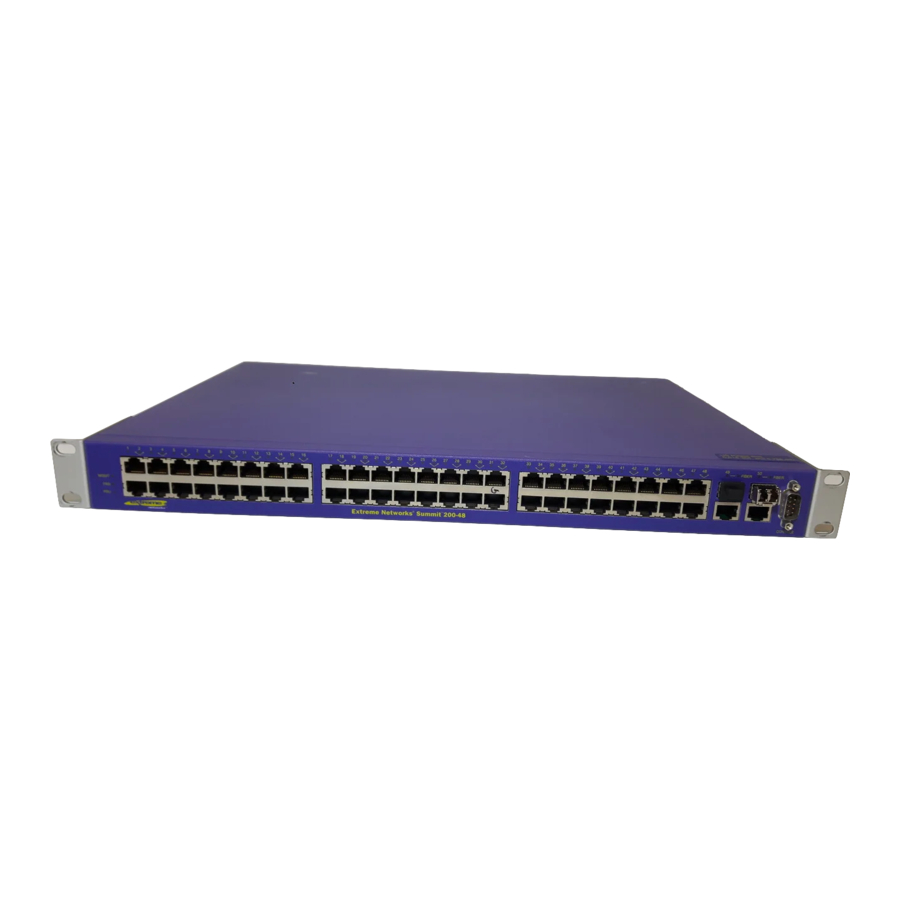
This label shows the unique Ethernet MAC address assigned to this device. NOTE The Summit 200-24 switch certification and safety label is located on the bottom of the switch. Summit 200-48 Switch Physical Features The Summit 200-48 switch is a compact enclosure (see Figure 3) one rack unit in height (1.75 inches or 44.45 mm) that provides 48 autosensing 10BASE-T/100BASE-TX ports using RJ-45 connectors. - Page 20 10/100Mbps Ethernet. The switch also has four Gigabit Ethernet uplink ports. These ports are labeled 49 and 50 on the front panel of the switch. Two of the ports are 10/100/1000BASE-T ports using RJ-45 connectors. The other two ports are unpopulated receptacles for mini-SFP GBICs, using optical fibers with LC connectors.
-
Page 21: Summit 200-48 Switch Rear View
Figure 4 shows the rear view of the Summit 200-48 switch. Figure 4: Summit 200-48 switch rear view Power Socket The Summit 200-48 switch automatically adjusts to the supply voltage. The power supply operates down to 90 V. Summit 200 Series Switch Installation and User Guide Indicates The Summit switch is operating normally. -
Page 22: Mini-Gbic Type And Hardware/Software Support
The Summit 200-48 switch certification and safety label is located on the bottom of the switch. Mini-GBIC Type and Hardware/Software Support The Summit 200 series switch supports the SFP GBIC, also known as the mini-GBIC, in three types: the SX mini-GBIC, which conforms to the 1000BASE-SX standard, the LX mini-GBIC, which conforms to the 1000BASE-LX standard, and the ZX mini-GBIC, a long-haul mini-GBIC that conforms to the IEEE 802.3z... - Page 23 General Total system budget Total optical system budget for the SX mini-GBIC is 11.5 dB. Extreme Networks recommends that 3 dB of the total budget be reserved for losses induced by cable splices, connectors, and operating margin. While 8.5 dB remains available for cable-induced attenuation, the 1000BASE-SX standard specifies supported distances of 275 meters over 62.5 micron multimode fiber and 550 meters over 50 micron...
- Page 24 (for example 0.25 dB/km), Extreme Networks recommends that 3 dB of the total budget be reserved for losses induced by cable splices, connectors, and operating margin. Figure 5 shows the total optical system budget between long range GBICs in various end-to-end combinations (ZX, ZX Rev 03, LX70, and LX100).
- Page 25 Table 9: Minimum attenuation requirements GBIC Type LX70 LX100 ZX (prior to Transceivers Rev 03) ZX Rev 03 ZX mini Summit 200 Series Switch Installation and User Guide Receivers ZX (prior to LX70 LX100 Rev 03) 9 dB 13 dB 7 dB...
- Page 26 Summit 200 Series Switch Overview Summit 200 Series Switch Installation and User Guide...
-
Page 27: Switch Installation
Determining the Switch Location The Summit 200 series switch is suited for use in the office, where it can be free-standing or mounted in a standard 19-inch equipment rack. Alternately, the device can be rack-mounted in a wiring closet or equipment room. -
Page 28: Following Safety Information
The Summit 200 series switch switch can be mounted in a rack, or placed free-standing on a tabletop. Rack Mounting CAUTION Do not use the rack mount kits to suspend the switch from under a table or desk, or to attach the switch to a wall. To rack mount the Summit 200 series switch: 1 Place the switch upright on a hard flat surface, with the front facing you. -
Page 29: Free-Standing
This relates only to stacking the devices directly one on top of one another. Apply the pads to the underside of the device by sticking a pad at each corner of the switch. Place the devices on top of one another, ensuring that the corners align. -
Page 30: Powering On The Switch
Cable connector: 9-pin female Screen Shell Ground Powering On the Switch To turn on power to the switch, connect the AC power cable to the switch and then to the wall outlet. Turn the on/off switch to the on position. Direction Screen Ground... -
Page 31: Checking The Installation
During the POST, all ports are temporarily disabled, the port LED is off, and the MGMT LED flashes. The MGMT LED flashes until the switch successfully passes the POST. If the switch passes the POST, the MGMT LED is solid green. If the switch fails the POST, the MGMT LED is amber. -
Page 32: Installing Or Replacing A Mini-Gigabit Interface Connector (Mini-Gbic)
WARNING! Mini-GBICs can emit invisible laser radiation. Avoid direct eye exposure to beam. Mini-GBICs are a class 1 laser device. Use only devices approved by Extreme Networks. NOTE Remove the LC fiber-optic connector from the mini-GBIC prior to removing the mini-GBIC from the switch. -
Page 33: Removing And Inserting A Mini-Gbic
If you see an amber blinking Mini-GBIC port status LED on your Summit 200 series switch, the mini-GBIC installed in your switch is one that is not approved or supported by Extreme Networks. To correct this problem, ensure that you install a mini-GBIC that is approved and supported by Extreme Networks. - Page 34 To insert a mini-GBIC connector: 1 Holding the mini-GBIC by its sides, insert the mini-GBIC into the SFP receptacle on the switch. 2 Push the mini-GBIC into the SFP receptacle until you hear an audible click, indicating the mini-GBIC is securely seated in the SFP receptacle.
-
Page 35: Summary Of Features
• Software Factory Defaults on page 40 ExtremeWare is the full-featured software operating system that is designed to run on the Summit 200 series switch. This section describes the supported ExtremeWare features for the Summit 200 series switch. Summary of Features The Summit 200 series switch supports the following ExtremeWare features: •... -
Page 36: Virtual Lans (Vlans)
For more information on VLANs, see Chapter 7, “Virtual LANs (VLANs)”. Spanning Tree Protocol The Summit 200 series switch supports the IEEE 802.1D Spanning Tree Protocol (STP), which is a bridge-based mechanism for providing fault tolerance on networks. STP enables you to implement parallel paths for network traffic, and ensure that: •... -
Page 37: Quality Of Service
For information on load sharing, see Chapter 6, “Configuring Ports on a Switch”. ESRP-Aware Switches Extreme switches that are not running ESRP, but are connected on a network that has other Extreme switches running ESRP are ESRP-aware. When ESRP-aware switches are attached to ESRP-enabled switches, the ESRP-aware switches reliably perform fail-over and fail-back scenarios in the prescribed recovery times. -
Page 38: Software Licensing
ExtremeWare Overview and the FDB timer used by the other vendor’s layer 2 switch. As such, ESRP can be used with layer 2 switches from other vendors, but the recovery times vary. The VLANs associated with the ports connecting an ESRP-aware switch to an ESRP-enabled switch must be configured using an 802.1Q tag on the connecting port, or, if only a single VLAN is involved, as... -
Page 39: Security Licensing For Features Under License Control
Certain additional ExtremeWare security features, such as the use of Secure Shell (SSH2) encryption, might be under United States export restriction control. Extreme Networks ships these security features in a disabled state. In order to enable the use of these features, you must first obtain an export license, which you can do through Extreme Networks (at no extra charge). -
Page 40: Software Factory Defaults
ExtremeWare Overview Software Factory Defaults Table 11 shows factory defaults for ExtremeWare features supported on the Summit 200 series switch. Table 11: ExtremeWare Software Feature Factory Defaults for the Summit 200 Series Item Default Setting Serial or Telnet user account... -
Page 41: Accessing The Switch
If an asterisk (*) appears in front of the command-line prompt, it indicates that you have outstanding configuration changes that have not been saved. For more information on saving configuration changes, see Appendix D, “Software Upgrade and Boot Options”. Summit 200 Series Switch Installation and User Guide... -
Page 42: Syntax Helper
1-3,6 Summit 200 Series Switch Numerical Ranges Commands that require you to enter one or more port numbers on a Summit 200 series switch use the parameter in the syntax. A portlist can be a range of numbers, for example: <portlist>... -
Page 43: Names
Names All named components of the switch configuration must have a unique name. Names must begin with an alphabetical character and are delimited by whitespace, unless enclosed in quotation marks. Symbols You may see a variety of symbols shown as part of the command syntax. These symbols explain how to enter the command, and you do not type them as part of the command itself. -
Page 44: Command History
ExtremeWare “remembers” the last 49 commands you entered. You can display a list of these commands by using the following command: history Common Commands Table 14 describes common commands used to manage the switch. Commands specific to a particular feature are described in the other chapters of this guide. Table 14: Common Commands Command clear session <number>... - Page 45 [<name> | all] disable cli-config-logging disable clipaging disable idletimeouts disable ports <portlist> Summit 200 Series Switch Installation and User Guide Description Configures a recovery option for instances where an exception occurs in ExtremeWare. Specify one of the following: •...
-
Page 46: Configuring Management Access
If you specify the keyword all, the switch erases the currently selected configuration image in flash memory and reboots. As a result, all parameters are reset to default settings. Summit 200 Series Switch Installation and User Guide... -
Page 47: Administrator Account
Summit200-24:2> Administrator Account An administrator-level account can view and change all switch parameters. It can also add and delete users, and change the password associated with any account name. The administrator can disconnect a management session that has been established by way of a Telnet connection. If this happens, the user logged on by way of the Telnet connection is notified that the session has been terminated. -
Page 48: Creating A Management Account
Creating a Management Account The switch can have a total of 16 management accounts. You can use the default names (admin and user), or you can create new names and passwords for the accounts. Passwords can have a minimum of 0 characters and can have a maximum of 31 characters. -
Page 49: Domain Name Service Client Services
<domain_name> config dns-client delete <ipaddress> nslookup <hostname> show dns-client Summit 200 Series Switch Installation and User Guide utility can be used to return the IP address of a hostname. Description Adds a DNS name server(s) to the available server list for the DNS client. -
Page 50: Checking Basic Connectivity
Traceroute command enables you to trace the routed path between the switch and a destination traceroute endstation. The command syntax is: traceroute traceroute [<ip_address> | <hostname>] {from <src_ipaddress>} {ttl <TTL>} {port <port>}... - Page 51 Uses the specified source address in the ICMP packet. If not specified, the from address of the transmitting interface is used. Configures the switch to trace up to the time-to-live number of the switch. Uses the specified UDP port number. port...
- Page 52 Accessing the Switch Summit 200 Series Switch Installation and User Guide...
-
Page 53: Overview
• Access the CLI by connecting a terminal (or workstation with terminal-emulation software) to the console port. • Access the switch remotely using TCP/IP through one of the switch ports. Remote access includes: — Telnet using the CLI interface. — SSH2 using the CLI interface. -
Page 54: Using The Console Interface
Managing the Switch Using the Console Interface The CLI built into the switch is accessible by way of the 9-pin, RS-232 port labeled console, located on the front of the Summit 200 series switch. Once the connection is established, you will see the switch prompt and you can log in. - Page 55 IP address of the VLAN using the command-line interface, Telnet, or Web interface. All VLANs within a switch that are configured to use BOOTP to get their IP address use the same MAC address. Therefore, if you are using BOOTP relay through a router, the BOOTP server must be capable of differentiating its relay based on the gateway portion of the BOOTP packet.
-
Page 56: Disconnecting A Telnet Session
For example: config iproute add default 123.45.67.1 7 Save your configuration changes so that they will be in effect after the next switch reboot, by typing: save 8 When you are finished using the facility, log out of the switch by typing:... -
Page 57: Controlling Telnet Access
Because SSH2 is currently under U.S. export restrictions, before enabling SSH2, you must first obtain a security license, which you can do through Extreme Networks. The procedure for obtaining a security license key is described in Chapter 3, “ExtremeWare Overview”. -
Page 58: Using Snmp
ISBN 0-13-8121611-9 Published by Prentice Hall. Accessing Switch Agents To have access to the SNMP agent residing in the switch, at least one VLAN must have an IP address assigned to it. Supported MIBs In addition to private MIBs, the switch supports the standard MIBs listed in Appendix C. - Page 59 • System contact (optional)—The system contact is a text field that enables you to enter the name of the person(s) responsible for managing the switch. • System name—The system name is the name that you have assigned to this switch. The default name is the model name of the switch (for example, Summit1 switch).
-
Page 60: Displaying Snmp Settings
You cannot configure RADIUS and TACACS+ at the same time. You can define a primary and secondary RADIUS server for the switch to contact. When a user attempts to login using Telnet, http, or the console, the request is relayed to the primary RADIUS server, and then to the secondary RADIUS server, if the primary does not respond. - Page 61 RADIUS port number to use when talking to the RADIUS server. The default port value is 1645. The client IP address is the IP address used by the RADIUS server for communicating back to the switch. RADIUS commands are described in Table 19.
- Page 62 Unconfigures the radius client configuration. Unconfigures the radius accounting client configuration. AAA server application, © [type] [version] [prefix] -------------- --------- type = nas type=nas type nas type proxy -------- pm1. pm2. Summit 200 Series Switch Installation and User Guide...
- Page 63 RADIUS Per-Command Configuration Example Building on this example configuration, you can use RADIUS to perform per-command authentication to differentiate user capabilities. To do so, use the Extreme-modified RADIUS Merit software that is available from the Extreme Networks web server at http://www.extremenetworks.com/extreme/support/otherapps.htm or by contacting Extreme...
- Page 64 *, configure iproute *, disable *, show fdb delete *, configure rip add albert command, the enable command, but can perform no other functions on the switch. We has these capabilities. gerald with support for per-command authentication: users .
-
Page 65: Configuring Tacacs
RADIUS client. The ExtremeWare version of TACACS+ is used to authenticate prospective users who are attempting to administer the switch. TACACS+ is used to communicate between the switch and an authentication database. -
Page 66: Using Network Login
• Until authentication takes place, ports on the VLAN are kept in a non-forwarding state. • Each mode requires the user to open a web browser with the IP address of the switch. This is the only address that the client can reach in a non-authenticated state. -
Page 67: Using Network Login In Campus Mode
VLAN. In this case, network login can be enabled on one port for each VLAN. Example Configuration Using Campus Mode This example creates a permanent VLAN named corp on the switch. This VLAN will be used for authentication through a RADIUS server. The RADIUS server is 10.201.26.243 and the IP address of the... - Page 68 Managing the Switch switch is 10.201.26.11. The secret is “secret”. A temporary VLAN named temporary is created and port 9 is added. Network login is enabled on the port. create vlan corp config corp ipaddress 10.201.26.11/24 config radius primary server 10.201.26.243 client-ip 10.201.26.11...
-
Page 69: Using Network Login In Isp Mode
Using Network Login in ISP Mode In ISP mode, a RADIUS server might be used to provide user authentication. No Extreme-specific lines are required for the dictionary or the user file. Configuring ISP Mode Configure the switch to use network login in ISP mode, using this command: enable netlogin ports <portlist>... -
Page 70: Dhcp Server On The Switch
9 vlan corp DHCP Server on the Switch A DHCP server with limited configuration capabilities is included in the switch to provide IP addresses to clients. DHCP is enabled on a per port, per VLAN basis. To enable or disable DHCP on a port in a VLAN, use one of the following commands: enable dhcp ports <portlist>... -
Page 71: Disabling Network Login
The following example enables EAPOL frame flooding on a Summit 200 series switch: enable eapol-flooding When EAPOL flooding is enabled on the switch, you can verify that status by using the command: show config The following example disables EAPOL frame flooding on a Summit 200 series switch:... -
Page 72: Using The Simple Network Time Protocol
4 If you would like this switch to use a directed query to the SNTP server, configure the switch to use the SNTP server(s). If the switch listens to SNTP broadcasts, skip this step. To configure the switch to use a directed query, use the following command: config sntp-client [primary | secondary] server [<ip_address>... - Page 73 5 Optionally, the interval for which the SNTP client updates the real-time clock of the switch can be changed using the following command: config sntp-client update-interval <seconds> The default sntp-client update-interval 6 You can verify the configuration using the following commands: —...
- Page 74 Istanbul, Turkey; Jerusalem, Israel; Harare, Zimbabwe Kuwait; Nairobi, Kenya; Riyadh, Saudi Arabia; Moscow, Russia; Tehran, Iran Abu Dhabi, UAE; Muscat; Tblisi; Volgograd; Kabul New Delhi, Pune, Allahabad, India Wellington, New Zealand; Fiji, Marshall Islands Summit 200 Series Switch Installation and User Guide...
-
Page 75: Sntp Configuration Commands
SNTP Example In this example, the switch queries a specific SNTP server and a backup SNTP server. The switch is located in Cupertino, CA, and an update occurs every 20 minutes. The commands to configure the switch are as follows:... - Page 76 Managing the Switch Summit 200 Series Switch Installation and User Guide...
-
Page 77: Configuring Ports On A Switch
By default, all ports are enabled. To enable or disable one or more ports, use the following command: [enable | disable] ports <portlist> For example, to disable ports 3, 5, and 12 through 15 on a Summit 200 series switch, use the following command: disable ports 3,5,12-15 Even though a port is disabled, the link remains enabled for diagnostic purposes. - Page 78 3-5 auto-polarity off NOTE If you attempt to invoke this command on a Gigabit Ethernet switch port, the system displays a message indicating that the specified port is not supported by this feature. When autopolarity is disabled on one or more Ethernet ports, you can verify that status by using the...
-
Page 79: Switch Port Commands
<portlist> enable sharing <port> grouping <portlist> {address-based} restart ports <portlist> show ports {<portlist>} collisions Summit 200 Series Switch Installation and User Guide Description Changes the configuration of a group of ports. Specify the following: • auto off—The port will not autonegotiate the settings. -
Page 80: Load Sharing On The Switch
Load sharing must be enabled on both ends of the link or a network loop may result. The load-sharing algorithms do not need to be the same on both ends. This feature is supported between Extreme Networks switches only, but may be compatible with third-party trunking or link-aggregation algorithms. Check with an Extreme Networks technical representative for more information. -
Page 81: Configuring Switch Load Sharing
Configuring Switch Load Sharing To set up a switch to load share among ports, you must create a load-sharing group of ports. The first port in the load-sharing group is configured as the “master” logical port. This is the reference port used in configuration commands. -
Page 82: Load-Sharing Example
The following rules apply to the Summit 200 series switch: • Ports on the switch must be of the same port type. For example, if you use 100 Mbps ports, all ports on the switch must be 100 Mbps ports. -
Page 83: Port-Mirroring Commands
For optimum performance, mirror three or fewer ports at any given time. On the Summit 200-48 switch, all ports specified by mirror filters as well as the mirror output port must belong to the same port group. Port group 1 consists of ports 1 through 24 and port 49; port group 2 consists of ports 25 through 48 and port 50. -
Page 84: Extreme Discovery Protocol
Configuring Ports on a Switch Extreme Discovery Protocol The Extreme Discovery Protocol (EDP) is used to gather information about neighbor Extreme Networks switches. EDP is used to by the switches to exchange topology information. Information communicated using EDP includes: • Switch MAC address (switch ID). -
Page 85: Overview Of Virtual Lans
The term “VLAN” is used to refer to a collection of devices that communicate as if they were on the same physical LAN. Any set of ports (including all ports on the switch) is considered a VLAN. LAN segments are not restricted by the hardware that physically connects them. The segments are defined by flexible user groups you create with the command-line interface. -
Page 86: Types Of Vlans
VLANs. For example, on the Summit 200-24 switch in Figure 10, ports 1 through 8, and port 26 are part of VLAN Sales; ports 9 through 16, and port 25 are part of VLAN Finance; and ports 17 through 24 are part of VLAN Marketing. - Page 87 2 for each VLAN you want to have span across the switches. At least one port on each switch must be a member of the corresponding VLANs, as well. Figure 12 illustrates two VLANs spanning two switches. On system 1, ports 1 through 8, and port 26 are part of VLAN Accounting;...
-
Page 88: Tagged Vlans
VLAN named default with an 802.1Q VLAN tag (VLANid) of 1 assigned. Not all ports in the VLAN must be tagged. As traffic from a port is forwarded out of the switch, the switch determines (in real time) if each destination port should use tagged or untagged packet formats for that VLAN. - Page 89 Slot 7, Ports 1-8 & 17-24 In Figure 13 and Figure 14: • The trunk port on each switch carries traffic for both VLAN Marketing and VLAN Sales. • The trunk port on each switch is tagged. • The server connected to port 16 on system 1 has a NIC that supports 802.1Q tagging.
-
Page 90: Vlan Names
• All other stations use untagged traffic. As data passes out of the switch, the switch determines if the destination port requires the frames to be tagged or untagged. All traffic coming from and going to the server is tagged. Traffic coming from and going to the trunk ports is tagged. -
Page 91: Renaming A Vlan
• Once you change the name of the default VLAN, it cannot be changed back to default. • You cannot create a new VLAN named default. • You cannot change the VLAN name MacVlanDiscover. Although the switch accepts a name change, once it is rebooted, the original name is recreated. -
Page 92: Vlan Configuration Examples
<name> ipaddress VLAN Configuration Examples The following Summit 200 series switch example creates a tag-based VLAN named video. It assigns the VLANid 1000. Ports 4 through 8 are added as tagged ports to the VLAN. create vlan video... -
Page 93: Mac-Based Vlans
You can configure the source MAC address-to-VLAN mapping either offline or dynamically on the switch. For example, you could use this application for a roaming user who wants to connect to a network from a conference room. In each room, the user plugs into one of the designated ports on the switch and is mapped to the appropriate VLAN. -
Page 94: Mac-Based Vlan Limitations
The timed downloads are configurable in 24 hour intervals. When a switch reboots, the configuration is automatically downloaded immediately after booting, per the configured primary and secondary servers. - Page 95 00:00:00:00:ab:02 mac-group any engineering config mac-vlan add mac-address 00:00:00:00:cd:04 mac-group any sales config mac-vlan add mac-address 00:00:00:00:ab:50 mac-group any sales config mac-vlan add mac-address 00:00:00:00:cd:60 mac-group any sales save Summit 200 Series Switch Installation and User Guide...
- Page 96 Virtual LANs (VLANs) Summit 200 Series Switch Installation and User Guide...
-
Page 97: Overview Of The Fdb
FDB are flooded to all members of the VLAN. FDB Entry Types The Summit 200 series switch supports up to 8,191 layer 2 FDB entries and 2,047 layer 3 FDB entries. The following are four types of entries in the FDB: •... -
Page 98: How Fdb Entries Get Added
Blackhole entries are useful as a security measure or in special circumstances where a specific destination address must be discarded. Blackhole entries are treated like permanent entries in the event of a switch reset or power off/on cycle. Blackhole entries are never aged-out of the database. -
Page 99: Configuring Fdb Entries
<name> blackhole {source-mac | dest-mac | both} delete fdbentry {<mac_address> vlan <name> | all} Summit 200 Series Switch Installation and User Guide Description Clears dynamic FDB entries that match the filter. When no options are specified, the command clears all FDB entries. -
Page 100: Fdb Configuration Examples
EDP traffic, and packets destined to a permanent MAC address matching that port number, are forwarded. The default setting is enabled. Enables MAC address learning on one or more ports. Summit 200 Series Switch Installation and User Guide... -
Page 101: Overview Of Access Policies
Each packet arriving on an ingress port is compared to the access list in sequential order and is either forwarded to a specified QoS profile or dropped. These forwarded packets can also be modified by changing the 802.1p value and/or the DiffServe code point. Using access lists has no impact on switch performance. -
Page 102: Routing Access Policies
There are between twelve and fourteen access masks available in the Summit 200 series switch, depending on which features are enabled on the switch. Each access mask is created with a unique name and defines a list of fields that will be examined by any access control list that uses that mask (and by any rate limit that uses the mask). -
Page 103: Rate Limits
For packets that match a particular list and arrive at a rate that exceeds the limit, you can specify the following actions: • Drop—Drop the packets. Excess packets are not forwarded. • Permit with rewrite—Forward the packet, but modify the packet’s DiffServe code point. Summit 200 Series Switch Installation and User Guide Using Access Control Lists... -
Page 104: How Access Control Lists Work
Specifying a Default Rule You can specify a default access control list to define the default access to the switch. You should use an access mask with a low precedence for the default rule access control list. If no other access control list entry is satisfied, the default rule is used to determine whether the packet is forwarded or dropped. -
Page 105: Adding Access Mask, Access List, And Rate Limit Entries
5 blocks of ports on the hardware. The maximum number of rate-limiting rules allowed is 315 (63*5). This number is part of the total access control list rules (1014). Summit 200 Series Switch Installation and User Guide... -
Page 106: Deleting Access Mask, Access List, And Rate Limit Entries
NOTE On the Summit 200-48 switch, ACL ingress and egress ports must belong to the same port group. Port group 1 consists of ports 1 through 24 and port 49; port group 2 consists of ports 25 through 48 and port 50. -
Page 107: Access Control List Configuration Commands
[permit {qosprofile <qosprofile>} {set code-point <code_point>} {set dot1p <dot1p_value>} | permit-established | deny] Summit 200 Series Switch Installation and User Guide Description Creates an access list. The list is applied to all ingress packets. Options include: • <name>—Specifies the access control list name. - Page 108 SYN/ACK bit fields. • egressport—Specify the egress port • ports—Specifies the ingress port(s) on which this rule is applied. • precedence—Specifies the access mask precedence number. The range is 1 to 25,600. Summit 200 Series Switch Installation and User Guide...
- Page 109 {set code-point <code_point>} {set dot1p <dot1p_value>} limit <rate_in_Mbps> {exceed-action [drop | set code-point <code_point>} Summit 200 Series Switch Installation and User Guide Description Creates a rate limit. The rule is applied to all ingress packets. Options include: • <rule_name>—Specifies the rate limit name, from 1 to 31 characters.
-
Page 110: Access Control List Examples
This example uses an access list that permits TCP sessions (Telnet, FTP, and HTTP) to be established in one direction. The switch, shown in Figure 15, is configured as follows: • Two VLANs, NET10 VLAN and NET20 VLAN, are defined. - Page 111 10.10.10.100/32 ports 2 permit qp1 create access-list tcp2_1 ip_addr_mask ipprotocol tcp dest-ip 10.10.10.100/32 source-ip 10.10.20.100/32 ports 10 permit qp1 Figure 17 illustrates the outcome of this access list. Summit 200 Series Switch Installation and User Guide 10.10.20.1 NET20 VLAN ICMP Using Access Control Lists 10.10.20.100...
- Page 112 NOTE This rule has a higher precedence than the rule “tcp2_1” and “tcp1_2”. Figure 19 shows the final outcome of this access list. ICMP 10.10.20.100 Host B EW_035 EW_036 Summit 200 Series Switch Installation and User Guide...
- Page 113 The commands to create this rate limit is as follows: create access-mask port2_mask source-ip/24 ports precedence 100 create rate-limit port2_limit port2_mask source-ip 10.10.10.0/24 port 2 permit qp1 set code-point 7 limit 10 exceed-action drop Summit 200 Series Switch Installation and User Guide 10.10.20.100 10.10.20.1 NET20 VLAN...
-
Page 114: Using Routing Access Policies
Adding an Access Profile Entry Next, configure the access profile, using the following command: config access-profile <access_profile> add {<seq_number>} {permit | deny} [ipaddress <ipaddress> <mask> {exact}] The following sections describe the command. config access-profile add Summit 200 Series Switch Installation and User Guide... -
Page 115: Deleting An Access Profile Entry
VLAN can use only one access profile. Routing Access Policies for RIP If you are using the RIP protocol, the switch can be configured to use an access profile to determine: • Trusted Neighbor—Use an access profile to determine trusted RIP router neighbors for the VLAN on the switch running RIP. - Page 116 RIP protocol is used to communicate with other routers on the network. The administrator wants to allow all internal access to the VLANs on the switch, but no access to the router that connects to the Internet. The remote router that connects to the Internet has a local interface connected to the corporate backbone.
-
Page 117: Routing Access Policies For Ospf
• ASBR Filter—For switches configured to support RIP and static route re-distribution into OSPF, an access profile can be used to limit the routes that are advertised into OSPF for the switch as a whole. To configure an ASBR filter policy, use the following command: config ospf asbr-filter [<access_profile>... -
Page 118: Making Changes To A Routing Access Policy
Propagation of changes applied to RIP access policies depends on the protocol timer to age-out entries. NOTE Changes to profiles applied to OSPF typically require rebooting the switch, or disabling and re-enabling OSPF on the switch. Removing a Routing Access Policy To remove a routing access policy, you must remove the access profile from the routing protocol or VLAN. -
Page 119: Routing Access Policy Commands
ABR. Configures the router to use the access policy to limit the routes that are advertised into OSPF for the switch as a whole for switches configured to support RIP and static route re-distribution into OSPF. Routing Access Policy Commands... - Page 120 Configures the router to use the access policy to limit the routes that are advertised into OSPF for the switch as a whole for switches configured to support direct route re-distribution into OSPF. Configures RIP to suppress certain routes when performing route advertisements.
-
Page 121: Overview
NAT device rewrite the source IP address and Layer 4 port of the packets. Figure 23: NAT Overview Inside Outside switch Outgoing Outgoing Private Internet Network Incoming Incoming EW_078 Summit 200 Series Switch Installation and User Guide... -
Page 122: Network Address Translation (Nat)
NAT operates by replacing the inside IP packet’s source IP and Layer 4 port with an outside IP and Layer 4 port. The NAT switch maintains a connection table to map the return packets on the outside VLAN back into their corresponding inside sessions. -
Page 123: Nat Modes
The outside IP address and Layer 4 port space is evenly distributed to all possible inside hosts. This guarantees that no single inside host can prevent other traffic from flowing through the NAT device. Summit 200 Series Switch Installation and User Guide , it routes all traffic destined for... -
Page 124: Configuring Nat
All return packets must arrive on the same outside VLAN on which the session went out. For most configurations, make sure that the outside IP addresses specified in the rule are part of the outside VLAN’s subnet range, so that the switch can proxy the address resolution protocol (ARP) for those addresses. -
Page 125: Creating Nat Rules
IP addresses the switch will translate the inside IP addresses to. If the netmask for both the source and NAT addresses is /32, the switch will use static NAT translation. If the netmask for both the source and NAT addresses are not both /32, the switch will use dynamic NAT translation. -
Page 126: Creating Auto-Constrain Nat Rules
L4-ports. If you use the L4-port command after the destination IP/mask, the rule will match only if the port(s) specified are the destination L4-ports. Both options may be used together to further limit the rule. keywords, you can further limit the scope of the NAT rule so that Summit 200 Series Switch Installation and User Guide... -
Page 127: Configuring Timeouts
This command displays the current NAT connection table, including source IP/Layer 4 port mappings from inside to outside. Summit 200 Series Switch Installation and User Guide Description Configures the timeout for a TCP session that has been torn down or reset. The default setting is 60 seconds. -
Page 128: Disabling Nat
Network Address Translation (NAT) Disabling NAT To disable NAT, use the following command: disable nat Summit 200 Series Switch Installation and User Guide... -
Page 129: Chapter 11 Ethernet Automatic Protection Switching
Metropolitan Area Network (MAN) or large campuses (see Figure 24). Figure 24: Gigabit Ethernet fiber EAPS MAN ring Transit node Transit node Transit Gigabit Ethernet Fiber node EAPS MAN ring Transit node Master node EW_070 Summit 200 Series Switch Installation and User Guide... - Page 130 NOTE In order to use EAPS, you must enable EDP on the switch. For more information on EDP, refer to Chapter 6.
-
Page 131: Fault Detection And Recovery
NOTE The control VLAN is not blocked. Messages sent on the control VLAN must be allowed into the switch for the master node to determine whether the ring is complete. Figure 26: EAPS fault detection and protection switching S3 sends "link down"... -
Page 132: Restoration Operations
When the transit nodes receive the message to flush their forwarding databases, they perform these steps: 1 Flush their forwarding databases on the protected VLANs. 2 If the port state is set to Preforwarding, unblock all the previously blocked protected VLANs for the port. Summit 200 Series Switch Installation and User Guide... -
Page 133: Summit 200 Series Switches In Multi-Ring Topologies
Summit 200 series switches. Summit 200 series switches support EAPS Version 1 (EAPSv1) and only support a single EAPS domain per switch. • Depending on the network topology and the versions of EAPS (EAPSv1 vs. EAPSv2) running on the other EAPS nodes, there might be a requirement to configure STP support for EAPSv1 to prevent super loops—in the event of a break in the common link between the nodes interconnecting the... -
Page 134: Commands For Configuring And Monitoring Eaps
{<name>} [detail] unconfig eaps <name> [primary | secondary] port Description Configures the switch as either the EAPS master node or as an EAPS transit node for the specified domain. Configures the values of the polling timers the master node uses for the EAPS health-check packet that is circulated around the ring for the specified EAPS domain. -
Page 135: Creating And Deleting An Eaps Domain
The following command example identifies this switch as the master node for the domain named eaps_1. config eaps eaps_1 mode master The following command example identifies this switch as a transit node for the domain named eaps_1. config eaps eaps_1 mode transit Configuring EAPS Polling Timers... -
Page 136: Configuring The Primary And Secondary Ports
To configure a node port as primary or secondary, use the following command: config eaps <name> [primary | secondary] port <port number> The following command example adds port 2 of the switch to the EAPS domain “eaps_1” as the primary port. -
Page 137: Configuring The Eaps Control Vlan
Because the QoS profiles Qp7 and Qp8 share the same hardware queue in the Summit 200 series switch, you must limit the amount of traffic that uses these profiles; otherwise, the Summit 200 series switch may drop EAPS control packets, preventing EAPS from operating reliably. -
Page 138: Enabling And Disabling An Eaps Domain
To disable a specific EAPS domain, use the following command: disable eaps <name> Enabling and Disabling EAPS To enable the EAPS function for the entire switch, use the following command: enable eaps To disable the EAPS function for the entire switch, use the following command:... - Page 139 "rhsc" EAPS Domain has following Protected Vlan(s): Vlan Name "blue" "traffic" Number of Protected Vlans: 2 Summit 200 Series Switch Installation and User Guide command displays detailed EAPS show eaps {<name>} detail [Running: Yes] Port status: Up Tag status: Tagged...
- Page 140 Indicates whether EAPS is enabled on this domain. • Yes—EAPS is enabled on this domain. • no—EAPS is not enabled. The configured EAPS mode for this switch: transit or master. The port numbers assigned as the EAPS primary and secondary ports. On the master node, the port distinction indicates which port is blocked to avoid a loop.
- Page 141 1. These fields apply only to transit nodes; they are not displayed for a master node. 2. This list is displayed when you use the detail keyword in the show eaps command. Summit 200 Series Switch Installation and User Guide Description •...
- Page 142 Ethernet Automatic Protection Switching Summit 200 Series Switch Installation and User Guide...
-
Page 143: Overview Of Policy-Based Quality Of Service
• Dynamic Link Context System on page 154 Policy-based Quality of Service (QoS) is a feature of ExtremeWare and the Extreme switch architecture that allows you to specify different service levels for traffic traversing the switch. Policy-based QoS is an effective control mechanism for networks that have heterogeneous traffic patterns. -
Page 144: Applications And Types Of Qos
Quality of Service (QoS) NOTE As with all Extreme switch products, QoS has no impact on switch performance. Using even the most complex traffic groupings has no cost in terms of switch performance. Applications and Types of QoS Different applications have different QoS requirements. The following applications are ones that you will most commonly encounter and need to prioritize: •... -
Page 145: Web Browsing Applications
Table 37 lists the commands used to configure QoS. Table 37: QoS Configuration Commands Command config ports <portlist> qosprofile <qosprofile> config vlan <name> qosprofile <qosprofile> Summit 200 Series Switch Installation and User Guide ™ -based applications. In addition, Web-based Key QoS Parameters Minimum bandwidth, priority... -
Page 146: Traffic Groupings
Chapter 9. By supplying a named QoS profile at the end of the access list command syntax, you can prescribe the bandwidth management and priority handling for that traffic grouping. This level of packet filtering has no impact on performance. Summit 200 Series Switch Installation and User Guide... -
Page 147: Mac-Based Traffic Groupings
FDB: clear fdb Blackhole MAC Address Using the option configures the switch to not forward any packets to the destination MAC blackhole address on any ports for the VLAN specified. The option is configured using the following... -
Page 148: Explicit Class Of Service (802.1P And Diffserv) Traffic Groupings
Configuring 802.1p Priority Extreme switches support the standard 802.1p priority bits that are part of a tagged Ethernet packet. The 802.1p bits can be used to prioritize the packet, and assign it to a particular QoS profile. When a packet arrives at the switch, the switch examines the 802.1p priority field maps it to a specific hardware queue when subsequently transmitting the packet. - Page 149 Configuring 802.1p Priority When a packet is transmitted by the switch, you can configure the 802.1p priority field that is placed in the 802.1Q tag. You can configure the priority to be a number between 0 and 7, using the following command: config vlan <name>...
-
Page 150: Configuring Diffserv
Observing DiffServ Information When a packet arrives at the switch on an ingress port, the switch examines the first six of eight TOS bits, called the code point. The switch can assign the QoS profile used to subsequently transmit the packet based on the code point. - Page 151 An access list can be used to change the DiffServ code point in the packet prior to the packet being transmitted by the switch. This is done with no impact on switch performance. To replace the DiffServ code point, you will use an access list to set the new code point value. See Chapter 9, “Access Policies”, for more information on using access lists.
-
Page 152: Physical And Logical Groupings
QoS profile when the traffic is transmitted out to any other port. To configure a source port traffic grouping, use the following command: config ports <portlist> qosprofile <qosprofile> In the following modular switch example, all traffic sourced from port 7 uses the QoS profile named qp3 when being transmitted. config ports 7 qosprofile qp3... -
Page 153: Verifying Configuration And Performance
Verifying Configuration and Performance Once you have created QoS policies that manage the traffic through the switch, you can use the QoS monitor to determine whether the application performance meets your expectations. QoS Monitor The QoS monitor is a utility that monitors the incoming packets on a port or ports. The QoS monitor keeps track of the number of frames and the frames per second, sorted by 802.1p value, on each... -
Page 154: Modifying A Qos Configuration
Traffic Rate-Limiting The Summit 200 series switch rate-limiting method is based on creating a rate limit, a specific type of access control list. Traffic that matches a rate limit is constrained to the limit set in the access control list. -
Page 155: Dlcs Guidelines
EEM Policy Manager or ExtremeWare EPICenter Policy Manager. • When the host is moved from one port to another port on a switch, the old entry does not age out unless the host is rebooted or a user login operation is performed after the host is moved. - Page 156 Quality of Service (QoS) Summit 200 Series Switch Installation and User Guide...
-
Page 157: Status Monitoring
In this way, statistics can help you get the best out of your network. Status Monitoring The status monitoring facility provides information about the switch. This information may be useful for your technical support representative if you have a problem. ExtremeWare includes many show commands that display information about different switch functions and facilities. - Page 158 Status Monitoring and Statistics Table 44 describes commands that are used to monitor the status of the switch. Table 44: Status Monitoring Commands Command show diag show log {<priority>} show log config show memory {detail} show switch show tech-support show version Description Displays software diagnostics.
-
Page 159: Port Statistics
To view port statistics, use the following command: show ports <portlist> stats The following port statistic information is collected by the switch: • Link Status—The current status of the link. Options are: — Ready (the port is ready to accept a link). -
Page 160: Port Monitoring Display Keys
To view port receive errors, use the following command: show ports <portlist> rxerrors The following port receive error information is collected by the switch: • Receive Bad CRC Frames (RX CRC)—The total number of frames received by the port that were of the correct length, but contained a bad FCS value. -
Page 161: Setting The System Recovery Level
Information that is useful when performing detailed troubleshooting procedures. By default, log entries that are assigned a critical or warning level remain in the log after a switch reboot. Issuing a clear log command does not remove these static entries. To remove log entries of all... -
Page 162: Local Logging
• Message—The message contains the log information with text that is specific to the problem. Local Logging The switch maintains 1,000 messages in its internal log. You can display a snapshot of the log at any time by using the following command: show log {<priority>}... -
Page 163: Remote Logging
Remote Logging In addition to maintaining an internal log, the switch supports remote logging by way of the UNIX syslog host facility. To enable remote logging, follow these steps: 1 Configure the syslog host to accept and log messages. 2 Enable remote logging by using the following command:... -
Page 164: Logging Commands
Disables logging to a remote syslog host. Enables the logging of CLI configuration commands to the Syslog for auditing purposes. The default setting is enabled. Enables the log display. Enables logging to a remote syslog host. Summit 200 Series Switch Installation and User Guide... -
Page 165: Rmon
The workstation does not have to be on the same network as the probe, and can manage the probe by in-band or out-of-band connections. RMON Features of the Switch Of the nine groups of IETF Ethernet RMON statistics, the switch supports these four groups: • Statistics • History •... -
Page 166: Configuring Rmon
RMON requires one probe per LAN segment, and standalone RMON probes traditionally have been expensive. Therefore, Extreme’s approach has been to build an inexpensive RMON probe into the agent of each system. This allows RMON to be widely deployed around the network without costing more than traditional network management. -
Page 167: Event Actions
By default, RMON is disabled. However, even in the disabled state, the switch response to RMON queries and sets for alarms and events. By enabling RMON, the switch begins the processes necessary for collecting switch statistics. Event Actions The actions that you can define for each alarm are shown in Table 49. - Page 168 Status Monitoring and Statistics Summit 200 Series Switch Installation and User Guide...
-
Page 169: Spanning Tree Protocol (Stp)
STP is a part of the 802.1D bridge specification defined by the IEEE Computer Society. To explain STP in terms used by the 802.1D specification, the switch will be referred to as a bridge. Overview of the Spanning Tree Protocol STP is a bridge-based mechanism for providing fault tolerance on networks. -
Page 170: Defaults
• Manufacturing is defined on switch Y, switch Z, and switch M. • Engineering is defined on switch Y, switch Z, and switch M. • Marketing is defined on all switches (switch A, switch B, switch Y, switch Z, and switch M). Summit 200 Series Switch Installation and User Guide... - Page 171 STP could configure the topology in a number of ways to make it loop-free. In Figure 30, the connection between switch A and switch B is put into blocking state, and the connection between switch Y and switch Z is put into blocking state. After STP converges, all the VLANs can communicate, and all bridging loops are prevented.
-
Page 172: Configuring Stp On The Switch
STP topology. • All VLANs in each switch are members of the same STPD. STP can block traffic between switch 1 and switch 3 by disabling the trunk ports for that connection on each switch. Switch 2 has no ports assigned to VLAN marketing. Therefore, if the trunk for VLAN marketing on switches 1 and 3 is blocked, the traffic for VLAN marketing will not be able to traverse the switches. - Page 173 <stpd_name> add vlan <name> config stpd <stpd_name> forwarddelay <value> config stpd <stpd_name> hellotime <value> Summit 200 Series Switch Installation and User Guide Description Adds a VLAN to the STPD. Specifies the time (in seconds) that the ports in this STPD spend in the listening and learning states when the switch is the Root Bridge.
- Page 174 2 * (Hello Time + 1) and less than, or equal to 2 * (Forward Delay –1). Specifies the path cost of the port in this STPD. The range is 1 through 65,535. The switch automatically assigns a default path cost based on the speed of the port, as follows: •...
-
Page 175: Stp Configuration Example
STP Configuration Example The following Summit 200 series switch example creates and enables an STPD named Backbone_st. It assigns the Manufacturing VLAN to the STPD. It disables STP on ports 1 through 7 and port 12. create stpd backbone_st config stpd backbone_st add vlan manufacturing... - Page 176 Spanning Tree Protocol (STP) Summit 200 Series Switch Installation and User Guide...
-
Page 177: Overview Of Ip Unicast Routing
Each host using the IP unicast routing functionality of the switch must have a unique IP address assigned. In addition, the default gateway assigned to the host must be the IP address of the router interface. -
Page 178: Ip Unicast Routing
IP address and subnet on different VLANs. In Figure 32, a switch is depicted with two VLANs defined; Finance and Personnel. Ports 2 and 4 are assigned to Finance; ports 3 and 5 are assigned to Personnel. Finance belongs to the IP network 192.207.35.0;... -
Page 179: Populating The Routing Table
Populating the Routing Table The switch maintains an IP routing table for both network routes and host routes. The table is populated from the following sources: • Dynamically, by way of routing protocol packets or by ICMP redirects exchanged with other routers. -
Page 180: Subnet-Directed Broadcast Forwarding
Route sharing is useful only in instances where you are constrained for bandwidth. This is typically not the case using Extreme switches. Using route sharing makes router troubleshooting more difficult because of the complexity in predicting the path over which the traffic will travel. -
Page 181: Arp-Incapable Devices
When the IP host tries to communicate with the host at address 100.101.45.67, the IP hosts communicates as if the two hosts are on the same subnet, and sends out an IP ARP Request. The switch answers on behalf of the device at address 100.101.45.67, using its own MAC address. All subsequent data packets from 100.101.102.103 are sent to the switch, and the switch routes the packets to... -
Page 182: Configuring Ip Unicast Routing
[rip | bootp | icmp | static | ospf-intra | ospf-inter | ospf-as-external | ospf-extern1 | ospf-extern2] <priority> Configuring IP Unicast Routing This section describes the commands associated with configuring IP unicast routing on the switch. To configure routing, follow these steps: 1 Create and configure two or more VLANs. -
Page 183: Verification Commands
255.255.255.255 is assumed. When mac_address is not specified, the MAC address of the switch is used in the ARP Response. When always is specified, the switch answers ARP Requests without filtering requests that belong to the same subnet of the receiving router interface. - Page 184 1 is used. Use the unicast-only or multicast-only options to specify a particular traffic type. If not specified, both unicast and multicast traffic uses the default route. Summit 200 Series Switch Installation and User Guide...
- Page 185 {vlan <name>} Disables the generation of ICMP messages for disable ip-option loose-source-route disable ip-option record-route disable ip-option record-timestamp disable ip-option strict-source-route Summit 200 Series Switch Installation and User Guide Description Deletes a static address from the routing table. Deletes a blackhole address from the routing table.
- Page 186 IP interfaces. Enables the generation of ICMP port unreachable messages (type 3, code 3) when a TPC or UDP request is made to the switch, and no application is waiting for the request, or access policy denies the request. The default setting is enabled.
-
Page 187: Routing Configuration Example
{vlan <name>} unconfig icmp unconfig irdp Routing Configuration Example Figure 33 illustrates a switch that has two VLANs defined as follows: • Finance — Contains ports 2 and 4. — IP address 192.207.35.1. • Personnel —... -
Page 188: Displaying Router Settings
(FDB) table. If no option is specified, all IP FDB entries are displayed. Displays the contents of the IP routing table or the route origin priority. Displays IP statistics for the CPU of the system. Summit 200 Series Switch Installation and User Guide... -
Page 189: Resetting And Disabling Router Settings
{vlan <name>} disable irdp {vlan <name>} unconfig icmp unconfig irdp Summit 200 Series Switch Installation and User Guide Resetting and Disabling Router Settings Description Removes dynamic entries in the IP ARP table. Permanent IP ARP entries are not affected. -
Page 190: Configuring Dhcp/Bootp Relay
Configuration Protocol (DHCP) or BOOTP requests coming from clients on subnets being serviced by the switch and going to hosts on different subnets. This feature can be used in various applications, including DHCP services between Windows NT servers and clients running Windows 95. To configure the relay function, follow these steps: 1 Configure VLANs and IP unicast routing. -
Page 191: Configuring Udp-Forwarding
ICMP messages associated with unreachables, port-unreachables, time-exceeded, parameter-problems, redirects, time-stamp, and address-mask requests. For ICMP packets that are typically routed, you can apply access lists to restrict forwarding behavior. Access lists are described in Chapter 9. Summit 200 Series Switch Installation and User Guide... -
Page 192: Udp-Forwarding Commands
Displays the profile names, input rules of UDP port, destination IP address, or VLAN and the source VLANs to which the profile is applied. Removes the UDP-forwarding profile configuration for one or all VLANs. Summit 200 Series Switch Installation and User Guide... -
Page 193: Overview
Published by Addison-Wesley Publishing Company Overview The switch supports the use of two interior gateway protocols (IGPs); the Routing Information Protocol (RIP) and the Open Shortest Path First (OSPF) protocol for IP unicast routing. RIP is a distance-vector protocol, based on the Bellman-Ford (or distance-vector) algorithm. The distance-vector algorithm has been in use for many years, and is widely deployed and understood. -
Page 194: Rip Versus Ospf
To determine the best path to a distant network, a router using RIP always selects the path that has the least number of hops. Each router that data must traverse is considered to be one hop. Summit 200 Series Switch Installation and User Guide... -
Page 195: Routing Table
• Support for next-hop addresses, which allows for optimization of routes in certain environments. • Multicasting. RIP version 2 packets can be multicast instead of being broadcast, reducing the load on hosts that do not support routing protocols. Summit 200 Series Switch Installation and User Guide Overview of RIP... -
Page 196: Overview Of Ospf
The cost of a route is described by a single metric. NOTE A Summit 200 series switch can support up to two non-passive OSPF interfaces, and cannot be a designated or a backup designated router. Link-State Database Upon initialization, each router transmits a link-state advertisement (LSA) on each of its interfaces. -
Page 197: Areas
Hiding this information enables a significant reduction in LSA traffic, and reduces the computations needed to maintain the LSDB. Routing within the area is determined only by the topology of the area. Summit 200 Series Switch Installation and User Guide Overview of OSPF... - Page 198 The CLI command to control the NSSA function is similar to the command used for configuring a stub area, as follows: config ospf area <area_id> nssa {summary | nosummary} stub-default-cost <cost> {translate} Summit 200 Series Switch Installation and User Guide...
- Page 199 Virtual links are also used to repair a discontiguous backbone area. For example, in Figure 35, if the connection between ABR1 and the backbone fails, the connection using ABR2 provides redundancy so that the discontiguous area can continue to communicate with the backbone using the virtual link. Summit 200 Series Switch Installation and User Guide...
-
Page 200: Point-To-Point Support
OSPF routers and does not elect a DR or BDR. If you have three or more routers on the VLAN, OSPF will fail to synchronize if the neighbor is not configured. EW_017 Summit 200 Series Switch Installation and User Guide... -
Page 201: Route Re-Distribution
Both RIP and OSPF can be enabled simultaneously on the switch. Route re-distribution allows the switch to exchange routes, including static routes, between the two routing protocols. Figure 36 is an example of route re-distribution between an OSPF autonomous system and a RIP autonomous system. -
Page 202: Ospf Timers And Authentication
VLAN in the area at the time of configuration. If you add more VLANs to the area, you must configure the timers and authentication for the new VLANs explicitly. Summit 200 Series Switch Installation and User Guide... -
Page 203: Configuring Rip
{vlan <name>} config rip updatetime {<seconds>} config rip vlan [<name> | all] cost <number> enable rip Summit 200 Series Switch Installation and User Guide Description Configures RIP on an IP interface. When an IP interface is created, per-interface RIP configuration is disabled by default. - Page 204 Enables triggered updates. Triggered updates are a mechanism for immediately notifying a router’s neighbors when the router adds or deletes routes, or changes the metric of a route. The default setting is enabled. Summit 200 Series Switch Installation and User Guide...
-
Page 205: Rip Configuration Example
RIP Configuration Example RIP Configuration Example Figure 37 illustrates a switch that has two VLANs defined as follows: • Finance, which contains ports 2 and 4 and has the IP address 192.207.35.1 • Personnel, which contains ports 3 and 5 and has the IP address 192.207.36.1 Figure 37: RIP configuration example 192.207.35.1... -
Page 206: Displaying Rip Settings
{vlan <name>} Configuring OSPF Each switch that is configured to run OSPF must have a unique router ID. It is recommended that you manually set the router ID of the switches participating in OSPF, instead of having the switch automatically choose its router ID based on the highest interface IP address. - Page 207 <routerid> <areaid>] authentication [simple-password <password> | md5 <md5_key_id> <md5_key>| none | encrypted [simple-password <password> | md5 <md5_key_id> <md5_key>] Summit 200 Series Switch Installation and User Guide Description Configures the OSPF link type. Specify one of the following: • auto—ExtremeWare automatically determines the OSPF link type based on the interface type.
- Page 208 Configures an OSPF area as a stub area. exported into OSPF. If none is specified, no RIP and static routes are filtered. Configures OSPF database overflow. Configures an aggregated OSPF external route using the IP addresses specified. Summit 200 Series Switch Installation and User Guide...
- Page 209 <100M_cost> <1G_cost> config ospf routerid [automatic | <routerid>] config ospf spf-hold-time {<seconds>} config ospf vlan <name> area <areaid> Summit 200 Series Switch Installation and User Guide Description Deletes an aggregated OSPF external route. Removes a virtual link. Disables OSPF on one or all VLANs (router interfaces).
- Page 210 Enables the distribution of RIP routes into the OSPF domain. Once enabled, the OSPF router is considered to be an ASBR. The default tag number is 0. The default setting is disabled. Summit 200 Series Switch Installation and User Guide...
-
Page 211: Configuring Ospf Wait Interval
NOTE The OSPF standard specifies that wait times are equal to the dead router wait interval. Summit 200 Series Switch Installation and User Guide Description Enables the distribution of static routes into the OSPF domain. -
Page 212: Displaying Ospf Settings
If detail is specified, each entry includes complete LSA information. Displays virtual link information about a particular router or all routers. command. You can specify show ospf lsdb stats Summit 200 Series Switch Installation and User Guide option summary option displays the... -
Page 213: Resetting And Disabling Ospf Settings
{vlan <name> | area <areaid>} Resets one or all OSPF interfaces to the default Summit 200 Series Switch Installation and User Guide Description Deletes an OSPF area. Once an OSPF area is removed, the associated OSPF area and OSPF interface information is removed. - Page 214 Interior Gateway Routing Protocols Summit 200 Series Switch Installation and User Guide...
-
Page 215: Overview
IGMP query packets. IGMP query should be enabled when the switch is configured to perform IP unicast routing. IGMP snooping is a layer 2 function of the switch, and is enabled by default. It does not require multicast routing to be enabled. IGMP snooping optimizes the usage of network bandwidth and prevents multicast traffic from being flooded to parts of the network that do not need it. -
Page 216: Configuring Igmp And Igmp Snooping
10 to 2,147,483,647 seconds (68 years). The default setting is 260 seconds. Enables IGMP on a router interface. If no VLAN is specified, IGMP is enabled on all router interfaces. The default setting is enabled. Summit 200 Series Switch Installation and User Guide... -
Page 217: Displaying Igmp Snooping Configuration Information
Description Enables IGMP snooping on the switch. Specify the forward-mcrouter-only option to have the switch forward all multicast traffic to the multicast router only; otherwise, the switch forwards all multicast traffic to any IP router. Specify the with-proxy option to enable the IGMP snooping proxy. - Page 218 IP Multicast Groups and IGMP Snooping Summit 200 Series Switch Installation and User Guide...
-
Page 219: Safety Information
Safety Information Important Safety Information WARNING! Read the following safety information thoroughly before installing your Extreme Networks switch. Failure to follow this safety information can lead to personal injury or damage to the equipment. Installation, maintenance, removal of parts, and removal of the unit and components must be done by qualified service personnel only. -
Page 220: Power Cord
If service personnel disregard the instructions and attempt to replace the bq4830/DS1644, replace the lithium battery with the same or equivalent type, as recommended by the manufacturer. ), Type SVT or SJT, Summit 200 Series Switch Installation and User Guide... - Page 221 • The weight of the lithium contained in each coin cell is approximately 0.035 grams. • Two types of batteries are used interchangeably: — CR chemistry uses manganese dioxide as the cathode material. — BR chemistry uses poly-carbonmonofluoride as the cathode material. Summit 200 Series Switch Installation and User Guide Important Safety Information...
- Page 222 Safety Information Summit 200 Series Switch Installation and User Guide...
-
Page 223: Technical Specifications
Technical Specifications This appendix provides technical specifications for the following Summit 200 series switches: • Summit 200-24 Switch on page 223 • Summit 200-48 Switch on page 226 Summit 200-24 Switch Physical and Environmental Dimensions Weight Temperature and Humidity Power... - Page 224 Korean MIC Mark (MIC Approval, Emissions and Immunity) Mexico NOM/NYCE (Product Safety and EMC Approval) GOST (Russia) Taiwan CNS 13438:1997 Class A (BSMI Approval, Emissions) Certification Marks CE (European Community) TUV/GS (German Notified Body) TUV/S (Argentina) Summit 200 Series Switch Installation and User Guide...
- Page 225 Summit 200-24 Switch GOST (Russian Federation) C-Tick (Australian Communication Authority) ACN 090 029 066 Underwriters Laboratories (USA and Canada) MIC (South Korea) BSMI, Republic of Taiwan NOM (Mexican Official Normalization, Electronic Certification and Normalization) Summit 200 Series Switch Installation and User Guide...
-
Page 226: Summit 200-48 Switch
Storage Temperature: –40° to 70 ° C (–40° to 158° F) Operating Humidity: 10% to 95% relative humidity, noncondensing Standards: EN60068 to Extreme IEC68 schedule Power AC Line Frequency: 50 Hz to 60 Hz Input Voltage Options: 90 VAC to 264 VAC, auto-ranging Current Rating: 100-120/200-240 VAC 2.0/1.0 A... - Page 227 International Country Specific Certification Marks ACN 090 029 066 Summit 200 Series Switch Installation and User Guide FCC 47 CFR Part 15 Class A (US Emissions) ICES-003 Class A (Canada Emissions) 89/336/EEC EMC Directive ETSI/EN 300 386:2001 (EU Telecommunications Emissions...
- Page 228 Technical Specifications Summit 200 Series Switch Installation and User Guide...
-
Page 229: Supported Standards
Supported Standards ExtremeWare supports the following standards for the Summit 200 series switch. Standards and Protocols RFC 1058 RIP RFC 1723 RIP v2 RFC 1112 IGMP RFC 2236 IGMP v2 RFC 2328 OSPF v2 (incl. MD5 authentication) RFC 2154 OSPF with Digital Signatures... - Page 230 Supported Standards Summit 200 Series Switch Installation and User Guide...
-
Page 231: Downloading A New Image
• Boot Option Commands on page 236 Downloading a New Image The image file contains the executable code that runs on the switch. It comes preinstalled from the factory. As new versions of the image are released, you should upgrade the software running on your system. -
Page 232: Software Upgrade And Boot Options
Software Upgrade and Boot Options The switch can store up to two images: a primary and a secondary. When you download a new image, you must select into which image space (primary or secondary) the new image should be placed. If you do select not an image space, the system uses the primary image space. -
Page 233: Returning To Factory Defaults
• Modify the configuration using a text editor, and later download a copy of the file to the same switch, or to one or more different switches. • Send a copy of the configuration file to the Extreme Networks Technical Support department for problem-solving purposes. -
Page 234: Using Tftp To Download The Configuration
To download a complete configuration, use the following command: download configuration [<hostname> | <ipaddress>] <filename> After the ASCII configuration is downloaded by way of TFTP, you are prompted to reboot the switch. The downloaded configuration file is stored in current switch memory during the rebooting process, and is not retained if the switch has a power failure. -
Page 235: Remember To Save
Upgrading BootROM Upgrading BootROM is done using TFTP (from the CLI), after the switch has booted. Upgrade the BootROM only when asked to do so by an Extreme Networks technical representative. To upgrade the BootROM, use the following command: download bootrom [<hostname> | <ipaddress>] <filename>]... -
Page 236: Boot Option Commands
Software Upgrade and Boot Options For example, to change the image that the switch boots from in flash memory, press stored in primary or for the image stored in secondary. Then, press the selected on-board flash memory. To boot to factory default configuration, press the configured on-board flash. - Page 237 <hostname>] <filename> {every <time>} upload configuration cancel use configuration [primary | secondary] use image [primary | secondary] Summit 200 Series Switch Installation and User Guide Description Uploads the current run-time configuration to the specified TFTP server. If every <time> is specified, the switch automatically saves the configuration to the server once per day, at the specified time.
- Page 238 Software Upgrade and Boot Options Summit 200 Series Switch Installation and User Guide...
-
Page 239: Appendix E Troubleshooting
Switch does not power up: All products manufactured by Extreme Networks use digital power supplies with surge protection. In the event of a power surge, the protection circuits shut down the power supply. To reset, unplug the switch for 1 minute, plug it back in, and attempt to power up the switch. -
Page 240: Using The Command-Line Interface
Ensure that you enter the IP address of the switch correctly when invoking the Telnet facility. Check that Telnet access was not disabled for the switch. If you attempt to log in and the maximum number of Telnet sessions are being used, you should receive an error message indicating so. -
Page 241: Port Configuration
Because the other network device is not participating in auto-negotiation (and does not advertise its capabilities), parallel detection on the Extreme switch is only able to sense 10 Mbps versus 100 Mbps speed, and not the duplex mode. Therefore, the switch establishes the link in half duplex mode using the correct speed. -
Page 242: Vlans
Check to ensure that the transmit fiber goes to the receive fiber side of the other device, and vice-versa. All gigabit fiber cables are of the cross-over type. The Extreme switch has auto-negotiation set to on by default for gigabit ports. These ports need to be set to auto off (using the command ) if you are connecting it to config port <port #>... -
Page 243: Stp
CPU utilization by process. Contacting Extreme Technical Support If you have a network issue that you are unable to resolve, contact Extreme Networks technical support. Extreme Networks maintains several Technical Assistance Centers (TACs) around the world to answer networking questions and resolve network problems. - Page 244 Troubleshooting Summit 200 Series Switch Installation and User Guide...
-
Page 245: Index
BootROM menu, accessing prompt upgrading BPDU tunneling cable types and distances certification marks Summit 200-24 switch Summit 200-48 switch command history command shortcuts line-editing keys named components numerical ranges, Summit 200 series switch symbols syntax helper using... - Page 246 Telnet session Ethernet ports, autopolarity detection feature Events, RMON export restrictions security licensing SSH2 encryption protocol Extensible Authentication Protocol. See EAP Extreme Discovery Protocol See EDP ExtremeWare factory defaults features adding an entry aging entries blackhole entries configuration commands (table)
- Page 247 Summit 200-24 switch Summit 200-48 switch History, RMON ICMP configuration commands (table) IEEE 802.1Q IEEE 802.1x EAP Over LANs (EAPOL) Extensible Authentication Protocol (EAP) IGMP configuration commands (table) description disabling reset and disable commands (table) snooping...
- Page 248 VLANs port-mirroring and protocol analyzers description example switch configuration commands (table) power supply specifications Summit 200-24 switch Summit 200-48 switch powering on the switch power-off specifications Summit 200-24 switch Summit 200-48 switch primary image private community, SNMP...
- Page 249 60, 65 removing using Routing Information Protocol. See RIP routing table, populating routing. See IP unicast routing safety certifications Summit 200-24 switch Summit 200-48 switch safety information saving configuration changes scheduling configuration download secondary image security licensing description obtaining serial port.
- Page 250 Index socket, power software licensing security features SSH2 protocol, Extreme Networks support website Spanning Tree Protocol. See STP speed, ports split horizon SSH2 protocol authentication key description enabling licensing, Extreme Networks support website TCP port number stand-alone switch, enabling and disabling ports...
- Page 251 Summit 200 Series Switch Installation and User Guide types UDP-Forwarding voice applications, QoS web browsing applications, and QoS weight Summit 200-24 Summit 200-48 Index...
- Page 252 Index Summit 200 Series Switch Installation and User Guide...
-
Page 253: Index Of Commands
Summit 200 Series Switch Installation and User Guide config iproute add config iproute add blackhole config iproute add default config iproute delete 99, 147... - Page 254 163, 164 disable dhcp ports vlan disable diffserv examination ports 45, 161 disable dlcs disable dlcs ports disable eapol-flooding Summit 200 Series Switch Installation and User Guide 45, 72 45, 56, 91, 182 91, 92 145, 152 105, 107 105, 108...
- Page 255 Summit 200 Series Switch Installation and User Guide 134, 138 disable sntp-client disable ssh2 disable stpd disable stpd port disable syslog...
- Page 256 71, 72 134, 138 147, 154 183, 188 183, 188, 190 183, 188 182, 188 158, 162, 165 158, 165 57, 60 202, 212 80, 82 80, 151, 152, 154 80, 160 Summit 200 Series Switch Installation and User Guide...
- Page 257 Summit 200 Series Switch Installation and User Guide 80, 159 80, 159 147, 152, 153 106, 110 80, 81 73, 94, 154, 158, 235...
- Page 258 Index of Commands Summit 200 Series Switch Installation and User Guide...