GEM Q50 eSyStep Operating Instructions Manual
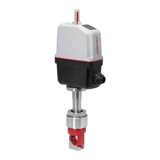
Motorized pinch valve
Hide thumbs
Also See for Q50 eSyStep:
- Operating instructions manual (52 pages) ,
- Operating instructions manual (53 pages)

Related Manuals for GEM Q50 eSyStep


Summary of Contents for GEM Q50 eSyStep
- Page 1 GEMÜ Q50 eSyStep Elektromotorisch betätigtes Schlauchquetschventil Motorized pinch valve Betriebsanleitung Operating instructions...
- Page 2 Alle Rechte, wie Urheberrechte oder gewerbliche Schutzrechte, werden ausdrücklich vorbehalten. All rights including copyrights or industrial property rights are expressly reserved. Dokument zum künftigen Nachschlagen aufbewahren. Keep the document for future reference. © GEMÜ Gebr. Müller Apparatebau GmbH & Co. KG 19.08.2021 GEMÜ Q50 2 / 108...
-
Page 3: Table Of Contents
Handnotbetätigung ........13 Inspektion und Wartung ........14 Fehlerbehebung ........... 15 Ausbau ..............16 Entsorgung ............17 Rücksendung ............18 Einbauerklärung nach 2006/42/EG (Maschinen- richtlinie) ............. 19 Konformitätserklärung nach 2014/30/EU (EMV- Richtlinie) ............www.gemu-group.com 3 / 108 GEMÜ Q50 eSyStep... -
Page 4: Allgemeines
Mögliche Folgen bei Nichtbeachtung. stücks! spezifisches Maßnahmen zur Vermeidung der Gefahr. Symbol Warnhinweise sind dabei immer mit einem Signalwort und teilweise auch mit einem gefahrenspezifischen Symbol ge- kennzeichnet. Folgende Signalwörter bzw. Gefährdungsstufen werden einge- setzt: GEMÜ Q50 eSyStep 4 / 108 www.gemu-group.com... -
Page 5: Sicherheitshinweise Am Produkt
Bei Betrieb: 9. Dokument am Einsatzort verfügbar halten. 10. Sicherheitshinweise beachten. 11. Das Produkt gemäß diesem Dokument bedienen. 12. Das Produkt entsprechend der Leistungsdaten betreiben. 13. Das Produkt ordnungsgemäß instand halten. 14. Wartungsarbeiten bzw. Reparaturen, die nicht in dem Do- kument beschrieben sind, nicht ohne vorherige Abstim- mung mit dem Hersteller durchführen. -
Page 6: Produktbeschreibung
Druckstück Edelstahl Ventilkörper 3.3 Beschreibung Ventilkörper Edelstahl/PA6 Das 2/2-Wege-Schlauchquetschventil GEMÜ Q50 eSyStep Verriegelungsring wird elektrisch betätigt. Der Antrieb eSyStep ist als Antrieb mit Schlauchaufnahme integriertem Stellungsregler ausgeführt. Das Ventil führt einen Schlauch, der zur Steuerung und Regelung von Medien durch Schlauchträger... -
Page 7: Typenschild
Baujahr 12103529 I 0001 Zählnummer Artikelnummer Rückmeldenummer Der Herstellungsmonat ist unter der Rückmeldenummer ver- schlüsselt und kann bei GEMÜ erfragt werden. Das Produkt wurde in Deutschland hergestellt. 4 Bestimmungsgemäße Verwendung GEFAHR Explosionsgefahr ▶ Gefahr von Tod oder schwersten Ver- letzungen. -
Page 8: Bestelldaten
3 Schlauch - Außendurchmesser 19,100 mm (3/4") Außendurchmesser 4 Werkstoff Ventilkörper Kunststoff Ausführung, Schlauchträger Edelstahl & Schlauchaufnahme PA 5 Spannung/Frequenz 24 V DC 6 Regelmodul Stellungsregler 7 Befestigungsflansch Mit Befestigungsflansch oben 8 Antriebsausführung Antriebsgröße 0 GEMÜ Q50 eSyStep 8 / 108 www.gemu-group.com... -
Page 9: Technische Daten
Antrieb Antriebsgröße 0 0,95 kg Ventilkörper 0,066 kg Edelstahl/PA6 0,228 kg Mechanische Umweltbe- Klasse 4M8 nach EN 60721-3-4:1998 dingungen: Vibration: 5g nach IEC 60068-2-6 Test Fc Schocken: 25g nach IEC 60068-2-27 Test Ea www.gemu-group.com 9 / 108 GEMÜ Q50 eSyStep... - Page 10 ≤ ±0,3 % v. E. Temperaturdrift: ≤ ±0,1 % / 10°K Auflösung: 12 bit Verpolschutz: ja (bis ± 24 V DC) 6.7.2 Digitale Eingangssignale Eingänge: Funktion über IO-Link wählbar (siehe Tabelle Funktionsübersicht Ein- und Ausgangssignale) GEMÜ Q50 eSyStep 10 / 108 www.gemu-group.com...
- Page 11 Min. cycle time: 20 ms (eSyStep Stellungsregler, Code S0, S5, S6) Vendor-ID: Device-ID: 1906801 (eSyStep Stellungsregler, Code S0, S5, S6), Product-ID: eSyStep Positioner (Code S0, S5, S6) ISDU Unterstützung: SIO Betrieb: IO-Link Spezifikation: V1.1 www.gemu-group.com 11 / 108 GEMÜ Q50 eSyStep...
- Page 12 6 Technische Daten IODD-Dateien können über https://ioddfinder.io-link.com/ oder www.gemu-group.com heruntergeladen werden. GEMÜ Q50 eSyStep 12 / 108 www.gemu-group.com...
-
Page 13: Ventilkörper, Ohne Befestigungsflansch
133,5 59,4 332,0 56,0 60,0 84,0 47,8 63,0 34,0 72,0 Maße in mm * D1 = Durchmesser ohne Dichtung, D2 = Durchmesser mit Dichtung 7.1 Ventilkörper, ohne Befestigungsflansch 12,0 12,0 Maße in mm www.gemu-group.com 13 / 108 GEMÜ Q50 eSyStep... -
Page 14: Herstellerangaben
▶ Schlauchleitungen fachgerecht verlegen und nicht unter- pitel „Technische Daten“). halb des Mindestbiegeradius biegen, siehe Herstelleran- gaben. 4. Lösungsmittel, Chemikalien, Säuren, Kraftstoffe u. ä. nicht Schlauchleitungen nicht knicken oder verdrehen. mit GEMÜ Produkten und deren Ersatzteilen in einem ● Raum lagern. HINWEIS 9 Einbau Werkzeug! ▶... -
Page 15: Einbaulage
3. Alle Sicherheits- und Schutzeinrichtungen wieder anbrin- gen bzw. in Funktion setzen. 9.4 Montage mit Befestigungsflansch 1. Das Gehäuse vor der Montage des Antriebs gemäß Bohr- bild im Kapitel „Abmessungen“ so bearbeiten, dass der Ventilkörper durch die Aussparung geführt werden kann. -
Page 16: Elektrischer Anschluss
7-poliger Stecker Fa. Binder, Typ 693 Signalname Uv, 24 V DC Versorgungsspannung Digitaleingang 1 Digitaleingang 2 Digitalein- / ausgang Digitalausgang, IO-Link n.c. Anschluss X2 5-poliger M12-Einbaustecker, A-kodiert Signalname I+/U+, Sollwerteingang I-/U-, Sollwerteingang I+/U+, Istwertausgang GEMÜ Q50 eSyStep 16 / 108 www.gemu-group.com... - Page 17 Auf / Zu / Error / Error+Warnung Analogeingang 4 – 20 mA / 0 – 20 mA / 0 – 4 – 20 mA 4 – 20 mA 10 V Analogausgang 4 – 20 mA / 0 – 20 mA / 0 – 4 – 20 mA 4 – 20 mA 10 V www.gemu-group.com 17 / 108 GEMÜ Q50 eSyStep...
-
Page 18: Spezifische Daten Io-Link (Pin 6)
Steckverbinder und die Stromaufnahme des Antriebs sind nicht konform zur IO-Link Spezifikation. 11.1 Betrieb an IO-Link 11.1.1 Betrieb an SPS als 24 V Gerät Der elektromotorische Antrieb GEMÜ eSyStep kann ohne Einschränkungen direkt an einer SPS-Steuerung betrieben werden. Technische Daten des Produkts und der SPS müssen eingehalten werden. Position... - Page 19 2. Pin 4 (CQ) des Masters mit Pin 6 des Produkts verbinden. Im IO-Link Betrieb kann Pin 6 nicht als Ausgangssignal von der SPS-Steuerung ausgewertet werden. Position Benennung eSyStep SPS mit Versorgungsspannung USB IO-Link Master USB-Schnittstelle Netzstecker Laptop www.gemu-group.com 19 / 108 GEMÜ Q50 eSyStep...
- Page 20 Spannungsversorgungen verbunden ist. In dem Fall erfolgt der Anschluss des Masters wie bei gleicher Spannungs- versorgung ● Pin 4 (CQ) IO-Link Master mit Pin 6 des Produkts verbinden. Pin 3 (L-) IO-Link Master nicht anschließen. (L-) Position Benennung eSyStep B1 und B2 Versorgungsspannungen USB IO-Link Master GEMÜ Q50 eSyStep 20 / 108 www.gemu-group.com...
-
Page 21: Prozessdaten
1 → Process valve in Closed position Operating mode 0 → Normal operation 1 → Initialization mode Valve position analog 8 … 23 Position of the valve in the range 0 … 1000 www.gemu-group.com 21 / 108 GEMÜ Q50 eSyStep... -
Page 22: Parameterübersicht
„eSyStep Positio- ner“ 0x13 Product ID Produkt ID auslesen „eSyStep Positio- ner“ 0x15 Serial number Seriennummer aus- „XXXXXXXX/YYYY“ lesen 0x16 Hardware revision Hardware Version „Rev. XX/XX“ auslesen 0x17 Firmware revision Softwareversion „V X.X.X.X.“ auslesen GEMÜ Q50 eSyStep 22 / 108 www.gemu-group.com... - Page 23 2 → Output error 3 → Output error & warning 0x4E R / W Logic digital inputs / Input 1 Logischen Digitalen 0 → Active high outputs Eingang 1 konfigu- 1 → Active low rieren www.gemu-group.com 23 / 108 GEMÜ Q50 eSyStep...
- Page 24 0 … 4095 Endlage ZU 0 … 4095 0x60 Analog values Poti Analogwert Poten- 0 … 4095 tiometer Supply voltage Analogwert Versor- 0 … 4095 gungsspannung Temperature Analogwert Tempe- 0 … 4095 ratursensor GEMÜ Q50 eSyStep 24 / 108 www.gemu-group.com...
- Page 25 R / W I max Maximalen Stro- 200 … 220 meingang festlegen (20,0 … 22,0 mA) R / W U max Maximalen Span- 100 … 110 nungseingang fest- (10,0 … 11,0 V) legen www.gemu-group.com 25 / 108 GEMÜ Q50 eSyStep...
- Page 26 2 → 0 … 10 V R / W Minimalen Signal- 0 … Max ausgang festlegen (0,0 % … Max) R / W Maximalen Signal- 1000 Min … 1000 ausgang festlegen (Min … 100 %) GEMÜ Q50 eSyStep 26 / 108 www.gemu-group.com...
-
Page 27: Parameter
R / W 1 Byte Data storage index Data Storage Cmd UIntegerT8 1 Byte State Property UIntegerT8 4 Byte Data Storage Size UIntegerT32 4 Byte Parameter Checks- UIntegerT32 41 Byte Index List OctetStringT www.gemu-group.com 27 / 108 GEMÜ Q50 eSyStep... - Page 28 Parameter Type Values Index Rights 0x0D 8 Byte Profile ArrayT 0x8000 Characteristics 0x8002 0x8003 0x8100 Beschreibung Parameterwerte Indexname Parameter Werte Beschreibung Profile Characteristics 0x8000 Geräte-Identifikation Objekte 0x8002 Prozessdatenabbildung 0x8003 Diagnose 0x8100 Externe Identifikation GEMÜ Q50 eSyStep 28 / 108 www.gemu-group.com...
- Page 29 11.4.8 Product name Mit dem Parameter Product name kann der Gerätename im ASCII Format ausgelesen werden. Index Sub- Off- Access Length Indexname Parameter Type Values Index Rights 0x12 18 Byte Product name StringT "eSyStep Positioner" www.gemu-group.com 29 / 108 GEMÜ Q50 eSyStep...
- Page 30 Mit dem Parameter Application specific tag kann ein 32 Zeichen langer Text im Gerät gespeichert werden. Zum Beispiel Einbauort, Funktion, Einbau-Datum..Index Sub- Off- Access Length Indexname Parameter Type Values Index Rights 0x18 R / W 32 Byte Application StringT „**************** " specific tag GEMÜ Q50 eSyStep 30 / 108 www.gemu-group.com...
- Page 31 Off- Access Length Indexname Parameter Type Values Index Rights 0x25 39 Byte Detailed Device Sta- ArrayT Siehe Kapitel 12.5 Events Beschreibung Parameterwerte Indexname Parameter Werte Beschreibung Detailed Device Status Siehe Kapitel 12.5 Events www.gemu-group.com 31 / 108 GEMÜ Q50 eSyStep...
- Page 32 Mit dem Parameter Function digital inputs können Funktionen der digitalen Eingänge konfiguriert werden. Index Sub- Off- Access Length Indexname Parameter Type Default Values Rights 0x4B R / W 3 Bit Function digital in- Input 1 uint:8 puts R / W 3 Bit Input 2 uint:8 GEMÜ Q50 eSyStep 32 / 108 www.gemu-group.com...
- Page 33 Bei aktivem Signal arbeitet das Gerät normal. Bei Weg- fall des Signals fährt das Gerät in Sicherheitsstellung. Die Si- cherheitsstellung wird mittels des Parameters Error Action (Index 0x4F (siehe 'Error Action')) definiert. (Init) Eingang kann als Initialisierungs-Eingang verwendet werden. www.gemu-group.com 33 / 108 GEMÜ Q50 eSyStep...
- Page 34 (Output Error & Warning) Fehler und Warnungen ausgeben. (Input Init) Ein- / Ausgang als Initialisierungseingang konfigu- rieren. Type in- / output (Push-Pull) Ausgang als Push-Pull konfigurieren. (NPN) Ausgang als NPN konfigurieren. (PNP) Ausgang als PNP konfigurieren. GEMÜ Q50 eSyStep 34 / 108 www.gemu-group.com...
- Page 35 (Active low) Eingang 2 invertiert. Input / output 1 (Active high) Ein- / Ausgang nicht invertiert. (Active low) Ein- / Ausgang invertiert. Output 2 (Active high) Ausgang nicht invertiert. (Active low) Ausgang invertiert. www.gemu-group.com 35 / 108 GEMÜ Q50 eSyStep...
- Page 36 (Hold) Antrieb bleibt bei einem Fehler in der aktuellen Stel- lung stehen. (Open) Antrieb fährt bei einem Fehler in Stellung AUF. (Close) Antrieb fährt bei einem Fehler in Stellung ZU. Error time 1 … 1000 Zeitverzögerung zwischen Fehlererkennung und Fehlermel- dung festlegen. GEMÜ Q50 eSyStep 36 / 108 www.gemu-group.com...
- Page 37 Betriebsmodus für Stellungsregler aktiviert. Betriebsmodus für AUF/ZU-Steuerung aktiviert. IO-Link process data (Disabled) Verwendung von IO-Link Prozessdaten (siehe Ka- pitel 11.2, Seite 21) ist deaktiviert. (Enabled) Verwendung von IO-Link Prozessdaten (siehe Kapi- tel 11.2, Seite 21) ist aktiviert. www.gemu-group.com 37 / 108 GEMÜ Q50 eSyStep...
- Page 38 Beschreibung Parameterwerte Indexname Parameter Werte Beschreibung Initialized positions Open 0 … 4092 Analogwert Ventilstellung AUF Close 0 … 4092 Analogwert Ventilstellung ZU Stroke 0 … 4092 Analogwert Hub (Differenz zwischen AUF und ZU). GEMÜ Q50 eSyStep 38 / 108 www.gemu-group.com...
- Page 39 Aktuellen Analogwert des Potentiometers auslesen. Supply voltage 0 … 4095 Aktuellen Analogwert der Versorgungsspannung auslesen. Temperature 0 … 4095 Aktuellen Analogwert des Temperatursensors auslesen. Set value (W) 0 … 4095 Aktuellen Analogwert des Sollwerts auslesen. www.gemu-group.com 39 / 108 GEMÜ Q50 eSyStep...
- Page 40 Kraft des Ventils einstellen. Werkseitig je nach Ventiltyp vor- eingestellt. Force initialization 1 … 6 Kraft während der Initialisierung einstellen. Werksseitig je nach Ventiltyp voreingestellt. Krafteinstellungen Antriebsgröße Einstellparameter Kraft AG0 und AG1 Kleinste Kraft Maximale Kraft GEMÜ Q50 eSyStep 40 / 108 www.gemu-group.com...
- Page 41 Parameter Werte Beschreibung Open / close tight Open tight 800 … 1000 Dichtschließfunktion Ventilposition AUF einstellen. (80,0 … 100,0 %) Close tight 0 … 200 Dichtschließfunktion Ventilposition ZU einstellen. (0 … 20,0 %) www.gemu-group.com 41 / 108 GEMÜ Q50 eSyStep...
- Page 42 Min Pos … 1000 Hubbegrenzung des Regelbereichs in Ventilposition AUF ein- (Min Pos … stellen. 100,0 %) Min pos 0 … Max Pos Hubbegrenzung des Regelbereichs in Ventilposition ZU ein- (0,0 % … Max stellen. Pos) GEMÜ Q50 eSyStep 42 / 108 www.gemu-group.com...
- Page 43 Wert überschritten, kommt die Meldung „Sollwert zu groß“. U max 100 … 110 Maximalen Wert des Spannungseingangs festlegen. Wird der (10,0 … 11,0 V) eingestellte Wert überschritten, kommt die Meldung „Sollwert zu hoch. www.gemu-group.com 43 / 108 GEMÜ Q50 eSyStep...
-
Page 44: Events
Das Event tritt auf, wenn der Ventil ist blockiert (zum Bei- Ventil prüfen 0x8CE0 Motor blockiert ist. spiel Festkörper im Ventil ein- Ist das Ventil in Ordnung, Initia- geklemmt). lisierung durchführen Ventil korrodiert (fest geros- tet). GEMÜ Q50 eSyStep 44 / 108 www.gemu-group.com... - Page 45 Ventilstellung gelesen wird, die tilposition. in Richtung „Open“ nie erreicht Fehler beim Tausch einer werden kann. Membrane (Hub des Ventils im falschen Bereich). Antrieb wurde falsch auf Ventil aufgebaut (Hub des Ventils im falschen Bereich). www.gemu-group.com 45 / 108 GEMÜ Q50 eSyStep...
-
Page 46: Bedienung
ð LEDs OPEN und CLOSED blinken alternierend. 2. Ventil fährt automatisch in Stellung AUF. 3. Ventil fährt automatisch in Stellung ZU. 4. Initialisierungsmodus wird automatisch beendet. 5. Endlagen sind eingestellt. GEMÜ Q50 eSyStep 46 / 108 www.gemu-group.com... -
Page 47: Inspektion Und Wartung
4. Anlage bzw. Anlagenteil gegen Wiedereinschalten sichern. VORSICHT 5. Anlage bzw. Anlagenteil drucklos schalten. Verwendung falscher Ersatzteile! 6. GEMÜ Produkte, die immer in derselben Position sind, vier- ▶ Beschädigung des GEMÜ Produkts. mal pro Jahr betätigen. ▶ Herstellerhaftung und Gewährleistungsanspruch erlö- 7. - Page 48 2. Schlauchaufnahme demontieren (siehe Kapitel 13.3, Sei- te 48). 3. Antrieb A in Geschlossen-Position bringen. 3. Schlauchaufnahme 1 öffnen. 4. Schlauch entnehmen. 4. Druckstück 2 nach unten herausziehen. 13.3 Schlauchaufnahme demontieren 1. Schlauch entnehmen (siehe Kapitel 13.2, Seite 48). GEMÜ Q50 eSyStep 48 / 108 www.gemu-group.com...
- Page 49 13.6 Schlauchaufnahme montieren 1. Schlauchaufnahme demontieren (siehe Kapitel 13.3, Sei- te 48). 2. Schlauchaufnahme 1 einsetzen. 3. Befestigungsschraube c mit Innensechskantschlüssel festziehen. 13.7 Schlauch einsetzen 1. Schlauch entnehmen (siehe Kapitel 13.2, Seite 48). 2. Schlauch einlegen. www.gemu-group.com 49 / 108 GEMÜ Q50 eSyStep...
-
Page 50: Fehlerbehebung
Temperatur Fehler Betrieb Notstrom, Stellung AUF Betrieb Notstrom, Stellung ZU Betrieb Notstrom, Stellung unbekannt Sollwert zu klein Sollwert zu groß Wartung nötig, Stellung AUF Wartung nötig, Stellung ZU Wartung nötig, Stellung unbekannt GEMÜ Q50 eSyStep 50 / 108 www.gemu-group.com... - Page 51 Das Produkt schließt nicht bzw. nicht voll- Antriebsauslegung nicht für Betriebsbe- Antrieb verwenden, der für die Betriebsbe- ständig dingungen geeignet dingungen ausgelegt ist Fremdkörper im Produkt Das Produkt demontieren und reinigen Spannung nicht angelegt Spannung anlegen www.gemu-group.com 51 / 108 GEMÜ Q50 eSyStep...
-
Page 52: Ausbau
Entsorgung. 1. Auf Restanhaftungen und Ausgasung von eindiffundierten 1. Das Produkt reinigen. Medien achten. 2. Rücksendeerklärung bei GEMÜ anfordern. 2. Alle Teile entsprechend den Entsorgungsvorschriften / 3. Rücksendeerklärung vollständig ausfüllen. Umweltschutzbedingungen entsorgen. 4. Das Produkt mit ausgefüllter Rücksendeerklärung an GEMÜ... -
Page 53: Einbauerklärung Nach 2006/42/Eg (Maschinenrichtlinie)
1.1.5, 1.2.1, 1.2.2, 1.2.3, 1.2.5, 1.3., 1.3.2, 1.3.4, 1.3.7, 1.3.8, 1.3.9, 1.5.3, 1.5.5, 1.5.14, 1.6.1, 1.6.3 Ferner wird erklärt, dass die speziellen technischen Unterlagen gemäß Anhang VII Teil B erstellt wurden. Der Hersteller bzw. der Bevollmächtigte verpflichten sich, einzelstaatlichen Stellen auf begründetes Verlangen die speziellen Un- terlagen zu der unvollständigen Maschine zu übermitteln. -
Page 54: Konformitätserklärung Nach 2014/30/Eu (Emv-Richtlinie)
19 Konformitätserklärung nach 2014/30/EU (EMV-Richtlinie) 19 Konformitätserklärung nach 2014/30/EU (EMV-Richtlinie) EU-Konformitätserklärung gemäß 2014/30/EU (EMV-Richtlinie) Wir, die Firma GEMÜ Gebr. Müller Apparatebau GmbH & Co. KG Fritz-Müller-Straße 6-8 D-74653 Ingelfingen-Criesbach erklären, dass das unten aufgeführte Produkt die Sicherheitsanforderungen der EMV-Richtlinie 2014/30/EU erfüllt. Benennung des Produktes: GEMÜ... - Page 55 14 Troubleshooting ..........15 Removal .............. 16 Disposal .............. 17 Returns ..............18 Declaration of Incorporation according to 2006/42/EC (Machinery Directive) ....... 19 Declaration of conformity according to 2014/30/ EU (EMC Directive) ..........www.gemu-group.com 55 / 108 GEMÜ Q50 eSyStep...
-
Page 56: General Information
Warning notes are always marked with a signal word and sometimes also with a symbol for the specific danger. The following signal words and danger levels are used: DANGER Imminent danger! ▶ Non-observance can cause death or severe injury. GEMÜ Q50 eSyStep 56 / 108 www.gemu-group.com... -
Page 57: Safety Information On The Product
14. Do not carry out any maintenance work and repairs not de- scribed in this document without consulting the manufac- turer first. In cases of uncertainty: 15. Consult the nearest GEMÜ sales office. www.gemu-group.com 57 / 108 GEMÜ Q50 eSyStep... -
Page 58: Product Description
Valve body Stainless steel/PA6 3.3 Description Locking ring The GEMÜ Q50 eSyStep 2/2-way pinch valve is motorized. Tube holder The eSyStep actuator is designed as an actuator with integ- Tube carrier rated positioner. The valve guides a tube which is com-... -
Page 59: Product Label
12103529 I 0001 Counting number Item number Traceability number The month of manufacture is encoded in the traceability num- ber and can be obtained from GEMÜ. The product was manu- factured in Germany. 4 Correct use DANGER Danger of explosion ▶... -
Page 60: Order Data
4 Valve body material Plastic design, stainless steel tube carrier and PA tube holder 5 Voltage/frequency 24 V DC 6 Control module Positioner 7 Mounting flange With mounting flange above 8 Actuator version Actuator size 0 GEMÜ Q50 eSyStep 60 / 108 www.gemu-group.com... -
Page 61: Technical Data
Valve body 0.066 kg Stainless steel/PA6 0.228 kg Mechanical environ- Class 4M8 acc. to EN 60721-3-4:1998 mental conditions: Vibration: 5g acc. to IEC 60068-2-6 Test Fc Shock: 25g acc. to 60068-2-27 Test Ea www.gemu-group.com 61 / 108 GEMÜ Q50 eSyStep... - Page 62 Input type: passive Input resistance: 250 Ω Accuracy/linearity: ≤ ±0.3% of full flow Temperature drift: ≤ ±0.1% / 10°K Resolution: 12 bit Reverse battery protec- Yes (up to ± 24 V DC) tion: GEMÜ Q50 eSyStep 62 / 108 www.gemu-group.com...
- Page 63 PDout 3Byte; PDin 3 Byte; OnRequestData 2 Byte Min. cycle time: 20 ms (eSyStep positioner, code S0, S5, S6) Vendor-ID: Device-ID: 1906801 (eSyStep positioner, code S0, S5, S6), Product-ID: eSyStep Positioner (code S0, S5, S6) www.gemu-group.com 63 / 108 GEMÜ Q50 eSyStep...
- Page 64 6 Technical data ISDU support: SIO operation: IO-Link specification: V1.1 IODD files can be downloaded via https://ioddfinder.io-link.com/ or www.gemu-group.com. GEMÜ Q50 eSyStep 64 / 108 www.gemu-group.com...
-
Page 65: Valve Body, Without Mounting Flange
332.0 56.0 60.0 84.0 47.8 63.0 34.0 72.0 Dimensions in mm * D1 = diameter without seal, D2 = diameter with seal 7.1 Valve body, without mounting flange 12.0 12.0 Dimensions in mm www.gemu-group.com 65 / 108 GEMÜ Q50 eSyStep... -
Page 66: Manufacturer's Information
Do not kink or twist the tube lines. ● 4. Do not store solvents, chemicals, acids, fuels or similar NOTICE fluids in the same room as GEMÜ products and their spare parts. Tools ▶ The tools required for installation and assembly are not 9 Installation included in the scope of delivery. -
Page 67: Mounting Without Mounting Flange
2. Guide the valve body through the recess in the housing. The actuator's mounting flange must be flush with the housing. 3. Connect the mounting flange and housing using appropri- ate screws and washers (not included in the scope of de- livery). www.gemu-group.com 67 / 108 GEMÜ Q50 eSyStep... -
Page 68: Electrical Connection
Uv, 24 V DC supply voltage Digital input 1 Digital input 2 Digital input/output Digital output, IO-Link n.c. Connection X2 5-pin M12 plug, A-coded Signal name I+/U+, set value input I-/U-, set value input I+/U+, actual value output GEMÜ Q50 eSyStep 68 / 108 www.gemu-group.com... - Page 69 Digital input 2 Off/Open/Closed/Safe/On/Ini- Safe/On tialization Digital input/output Open/Closed/Error/Error and Error Error warning/Initialization Digital output Open/Closed/Error/Error and Closed Closed warning Analogue input 4–20 mA/0–20 mA/0–10 V 4–20 mA 4–20 mA Analogue output 4–20 mA/0–20 mA/0–10 V 4–20 mA 4–20 mA www.gemu-group.com 69 / 108 GEMÜ Q50 eSyStep...
-
Page 70: Specific Data Io-Link (Pin 6)
11.1 Operation on IO-Link 11.1.1 Operation on PLC as a 24 V device The motorized actuator GEMÜ eSyStep can be operated directly in a PLC control unit without limitations. Technical data of the product and of PLC must be complied with. - Page 71 During IO-Link operation, pin 6 cannot be evaluated by the PLC control unit as an output signal. Item Name eSyStep PLC with supply voltage USB IO-Link Master USB interface Mains plug – laptop www.gemu-group.com 71 / 108 GEMÜ Q50 eSyStep...
- Page 72 ● Connect pin 4 (CQ) IO-Link master with pin 6 of the product. Do not connect (pin 3) L- IO-Link master. (L-) Item Name eSyStep B1 and B2 Supply voltages USB IO-Link Master GEMÜ Q50 eSyStep 72 / 108 www.gemu-group.com...
-
Page 73: Process Data
1 → Process valve in Closed position Operating mode 0 → Normal operation 1 → Initialization mode Valve position analog 8 … 23 Position of the valve in the range 0 … 1000 www.gemu-group.com 73 / 108 GEMÜ Q50 eSyStep... -
Page 74: Parameter Overview
Read out product ID "eSyStep Posi- tioner" 0x15 Serial number Read out serial "XXXXXXXX/YYYY" number 0x16 Hardware revision Read out hardware "Rev. XX/XX" version 0x17 Firmware revision Read out software "V X.X.X.X." version GEMÜ Q50 eSyStep 74 / 108 www.gemu-group.com... - Page 75 1 → Active low Input / output 1 Configure logical di- 0 → Active high gital input/output 1 → Active low Output 2 Configure logical di- 0 → Active high gital output 1 → Active low www.gemu-group.com 75 / 108 GEMÜ Q50 eSyStep...
- Page 76 Operating times Open Operating time 0 to 255 OPEN (0 to 25.5s) Close Operating time 0 to 255 CLOSE (0 to 25.5s) 0x90 Drive sets Force Force, dependent on 1 … 6 valve used GEMÜ Q50 eSyStep 76 / 108 www.gemu-group.com...
- Page 77 1 → 4 to 20 mA 2 → 0 to 10 V Min. Determine minimum 0 to Max signal output (0.0% to Max) Determine max- 1000 Min to 1000 imum signal output (Min to 100%) www.gemu-group.com 77 / 108 GEMÜ Q50 eSyStep...
-
Page 78: Parameter
Index Rights 0x03 1 byte Data storage index Data Storage Cmd UIntegerT8 1 byte State Property UIntegerT8 4 bytes Data Storage Size UIntegerT32 4 bytes Parameter Check- UIntegerT32 41 bytes Index List OctetStringT GEMÜ Q50 eSyStep 78 / 108 www.gemu-group.com... - Page 79 8 bytes Profile ArrayT 0x8000 Characteristics 0x8002 0x8003 0x8100 Description of parameter values Index name Parameter Values Description Profile Characteristics 0x8000 Device identification objects 0x8002 Process data mapping 0x8003 Diagnostics 0x8100 External identification www.gemu-group.com 79 / 108 GEMÜ Q50 eSyStep...
- Page 80 The device name can be read out in ASCII format with the Product name parameter. Index Sub- Off- Access Length Index name Parameter Type Values Index Rights 0x12 18 byte Product name StringT "eSyStep Positioner" GEMÜ Q50 eSyStep 80 / 108 www.gemu-group.com...
- Page 81 A text with 32 characters can be stored in the device with the Application specific tag parameter. For example, installation location, function, installation date, etc. Index Sub- Off- Access Length Index name Parameter Type Values Index Rights 0x18 32 bytes Application StringT „**************** " specific tag www.gemu-group.com 81 / 108 GEMÜ Q50 eSyStep...
- Page 82 Index name Parameter Type Values Index Rights 0x25 39 byte Detailed Device ArrayT See chapter 12.5 Events Status Description of parameter values Index name Parameter Values Description Detailed Device Status See chapter 12.5 Events GEMÜ Q50 eSyStep 82 / 108 www.gemu-group.com...
- Page 83 The functions of the digital inputs can be configured with the Function digital inputs parameter. Index Sub- Off- Access Length Index name Parameter Type Default Values Rights 0x4B 3 bits Function digital in- Input 1 uint:8 puts 3 bits Input 2 uint:8 www.gemu-group.com 83 / 108 GEMÜ Q50 eSyStep...
- Page 84 If there is no signal, the device moves into the safety position. The safety position is defined by the parameter Error Action (index 0x4F (see "Error Action'"). (Init) Input can be used as an initialization input. GEMÜ Q50 eSyStep 84 / 108 www.gemu-group.com...
- Page 85 (Output Error & Warning) Output error and warnings. (Input Init) Configure input/output as initialization input. Type in- / output (Push-Pull) Configure output as Push-Pull. (NPN) Configure output as NPN. (PNP) Configure output as PNP. www.gemu-group.com 85 / 108 GEMÜ Q50 eSyStep...
- Page 86 (Active high) Input 2 not inversed. (Active low) Input 2 inversed. Input / output 1 (Active high) Input/output not inversed. (Active low) Input/output inversed. Output 2 (Active high) Output not inversed. (Active low) Output inversed. GEMÜ Q50 eSyStep 86 / 108 www.gemu-group.com...
- Page 87 (Open) Actuator moves to the OPEN position in case of an error. (Close) Actuator moves to the CLOSED position in case of an error. Error time 1 … 1000 Determine delay time between error detection and error mes- sage. www.gemu-group.com 87 / 108 GEMÜ Q50 eSyStep...
- Page 88 Operating mode for OPEN/CLOSE control activated. IO-Link process data (Disabled) Use of IO-Link process data (see “Process data“, page 73) is deactivated. (Enabled) Use of IO-Link process data (see “Process data“, page 73) is activated. GEMÜ Q50 eSyStep 88 / 108 www.gemu-group.com...
- Page 89 Description Initialized positions Open 0 … 4092 Analog value valve position OPEN Close 0 … 4092 Analog value valve position CLOSED Stroke 0 … 4092 Analog value stroke (difference between OPEN and CLOSED). www.gemu-group.com 89 / 108 GEMÜ Q50 eSyStep...
- Page 90 Read out current analog value of the supply voltage. Temperature 0 … 4095 Read out current analog value of the temperature sensor. Set value (W) 0 … 4095 Read out current analog value of the set value. GEMÜ Q50 eSyStep 90 / 108 www.gemu-group.com...
- Page 91 Force initialization 1 … 6 Set the force during initialization. Preset at the factory de- pending on the valve type. Force settings Actuator size Setting parameter Force AG0 and AG1 Minimum force Maximum force www.gemu-group.com 91 / 108 GEMÜ Q50 eSyStep...
- Page 92 Open / close tight Open tight 800 … 1000 Set the sealing function valve position OPEN. (80.0 … 100.0 %) Close tight 0 … 200 Set the sealing function valve position CLOSED. (0 … 20.0 %) GEMÜ Q50 eSyStep 92 / 108 www.gemu-group.com...
- Page 93 Set the stroke limiter of the control range in valve position (Min Pos to OPEN. 100.0%) Min pos 0 to Max Pos Set the stroke limiter of the control range in valve position (0.0% to Max CLOSED. Pos) www.gemu-group.com 93 / 108 GEMÜ Q50 eSyStep...
- Page 94 "Set value too high" is is- sued. U max 100 to 110 Determine maximum value of the voltage input. If the set (10.0 to 11.0 V) value is exceeded, the message "Set value too high" is is- sued. GEMÜ Q50 eSyStep 94 / 108 www.gemu-group.com...
-
Page 95: Events
Motor Unable To Move The event occurs when the Valve is blocked (for example, Check valve 0x8CE0 motor is blocked. solid stuck in valve). Carry out initialization if valve Valve corroded (rusted in is OK place). www.gemu-group.com 95 / 108 GEMÜ Q50 eSyStep... - Page 96 "Open" dir- Error when replacing a dia- ection. phragm (stroke of the valve in incorrect area). Actuator has been fitted on the valve incorrectly (stroke of the valve in the incorrect area). GEMÜ Q50 eSyStep 96 / 108 www.gemu-group.com...
-
Page 97: Operation
ð OPEN and CLOSED LEDs flash alternately. 2. Valve automatically moves into the OPEN position. 3. Valve automatically moves into the CLOSED position. 4. Initialization mode is automatically ended. 5. The end positions are set. www.gemu-group.com 97 / 108 GEMÜ Q50 eSyStep... -
Page 98: Inspection And Maintenance
Use of incorrect spare parts! 5. Depressurize the plant or plant component. ▶ Damage to the GEMÜ product. 6. Actuate GEMÜ products which are always in the same po- ▶ Manufacturer liability and guarantee will be void. sition four times a year. - Page 99 3. Move the actuator A to the closed position. 3. Open the tube holder 1. 4. Remove the tube. 13.3 Disassembling the tube holder 4. Pull the compressor 2 out downwards. 1. Remove the tube (see “Removing the tube“, page 99). www.gemu-group.com 99 / 108 GEMÜ Q50 eSyStep...
- Page 100 2. Insert the tube holder 1. 3. Tighten the fixing screw c using an Allen key. 13.7 Inserting the tube 1. Remove the tube (see “Removing the tube“, page 99). 2. Insert the tube. GEMÜ Q50 eSyStep 100 / 108 www.gemu-group.com...
-
Page 101: Troubleshooting
Emergency power operation, OPEN position Emergency power operation, CLOSED position Emergency power operation, position unknown Set value too small Set value too high Maintenance required, OPEN position Maintenance required, CLOSED position Maintenance required, position unknown www.gemu-group.com 101 / 108 GEMÜ Q50 eSyStep... - Page 102 The actuator design is not suitable for the Use an actuator that is designed for the close fully operating conditions operating conditions Foreign matter in the product Remove and clean the product Voltage is not connected Connect voltage GEMÜ Q50 eSyStep 102 / 108 www.gemu-group.com...
-
Page 103: Removal
3. Disassemble the product. Observe warning notes and goods can be processed only when this note is completed. If safety information. no return delivery note is included with the product, GEMÜ cannot process credits or repair work but will dispose of the 16 Disposal goods at the operator's expense. -
Page 104: Declaration Of Incorporation According To 2006/42/Ec (Machinery Directive)
18 Declaration of Incorporation according to 2006/42/EC (Machinery Directive) Declaration of Incorporation according to the EC Machinery Directive 2006/42/EC, Annex II, 1.B for partly completed machinery GEMÜ Gebr. Müller Apparatebau GmbH & Co. KG Fritz-Müller-Straße 6-8 74653 Ingelfingen-Criesbach, Germany declare that the following product Make: GEMÜ... -
Page 105: Declaration Of Conformity According To 2014/30/Eu (Emc Directive)
19 Declaration of conformity according to 2014/30/EU (EMC Directive) EU Declaration of Conformity in accordance with 2014/30/EU (EMC Directive) GEMÜ Gebr. Müller Apparatebau GmbH & Co. KG Fritz-Müller-Straße 6-8 74653 Ingelfingen-Criesbach, Germany declare that the product listed below complies with the safety requirements of the EMC Directive 2014/30/EU. - Page 106 GEMÜ Q50 106 / 108 www.gemu-group.com...
- Page 107 107 / 108 GEMÜ Q50...
- Page 108 Änderungen vorbehalten GEMÜ Gebr. Müller Apparatebau GmbH & Co. KG Subject to alteration *88727000* Fritz-Müller-Straße 6-8, 74653 Ingelfingen-Criesbach, Germany 08.2021 | 88727000 Phone +49 (0) 7940 1230 · info@gemue.de www.gemu-group.com...