Table of Contents
Advertisement
Quick Links
INSTALLATION/OPERATION &
AJX-44 SERIES
AJX-44CE
AJX-44CS
AJX-54 SERIES
AJX-54CE
AJX-54CS
October 13, 2014
P/N 7610-003-60-98 (Revision J)
TECHNICAL MANUAL
AJX-66 SERIES
AJX-76 SERIES
AND ASSOCIATED OPTION PACKAGES INCLUDING:
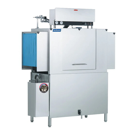
AJX-44 & AJX-54 SERIES RACK CONVEYOR DISHMACHINE
AJX-66CE
AJX-66CS
AJX-76CE
AJX-76CS
SIDE LOADER
AJX-80 SERIES
AJX-80CE
AJX-66CS
AJX-90 SERIES
AJX-90CE
AJX-90CS
Jackson WWS INC.
P.O. Box 1060
Barbourville, KY. 40906
(606) 523-9795
Fax: (606) 523-9196
www.jacksonwws.com
Advertisement
Table of Contents

Related Manuals for Jackson AJX-44 Series


Summary of Contents for Jackson AJX-44 Series
- Page 1 AJX-44 & AJX-54 SERIES RACK CONVEYOR DISHMACHINE INSTALLATION/OPERATION & TECHNICAL MANUAL AJX-44 SERIES AJX-66 SERIES AJX-80 SERIES AJX-44CE AJX-66CE AJX-80CE AJX-44CS AJX-66CS AJX-66CS AJX-54 SERIES AJX-76 SERIES AJX-90 SERIES AJX-54CE AJX-76CE AJX-90CE AJX-54CS AJX-76CS AJX-90CS AND ASSOCIATED OPTION PACKAGES INCLUDING: SIDE LOADER Jackson WWS INC.
- Page 2 The warranty registration card supplied with the machine must be returned to Jackson WWS within 30 days to validate the warranty. REPLACEMENT PARTS WARRANTY Jackson replacement parts are warranted for a period of 90 days from the date of installation or 180 days from the date of shipment from the factory, which ever occurs first.
- Page 3 STOP! PARE! ARRET! CALL 1-888-800-5672 TO REGISTER THIS PRODUCT! FAILURE TO DO SO WILL VOID THE WARRANTY! LLAME AL 1-888-800-5672 PARA REGISTRAR ESTE PRODUCTO! AL NO HACERLO LA GARANTIA SERA ANULADA! S.V.P . APPELER 1-888-800-5672 POUR ENREGISTRER CE PRODUIT, LA GARANTIE SERA ANNULEE POUR TOUT PRODUIT NON- ENREGISTREE...
- Page 4 REVISION MADE APPLICABLE REVISION DETAILS DATE 01-19-2009 Process Initial release of manual. 01-30-2009 Process Added 15kW heater option and adjusted amperage ratings. 10-06-2009 Added curtain installation diagram. Changed the part from a weldment (05700-021-67-50) to a cast- 10-09-2009 8044 ing (09515-003-58-12). Changed a dimension on page 30, the dimension between the 12-01-2009 mounting holes was indicated as 2.00”, but should have been...
- Page 5 80 = 80” wide machine 90 = 90” wide machine CE = Electrically heated CS = Steam heated Jackson WWS, INC. provides technical support for Model: all of the dishmachines detailed in this manual. We strongly recommend that you refer to this manual Serial No.:...
-
Page 6: Table Of Contents
TABLE OF CONTENTS SECTION DESCRIPTION PAGE SPECIFICATION INFORMATION Operating Characteristics Electrical Requirements AJX-44 Electric - Left to Right AJX-44 Electric - Right to Left AJX-44 Steam - Left to Right AJX-44 Steam - Right to Left AJX-66 Electric - Left to Right AJX-66 Electric - Right to Left AJX-66 Steam - Left to Right AJX-66 Steam - Right to Left... -
Page 7: Description Page
208-230 Volt, 50-60 Hz, 1 Phase 208-460 Volt, 50-60 Hz, 3 Phase AJX-66CS, AJX-76CS, AJX-80CS & AJX-90CS 208-230 Volt, 50-60 Hz, 1 Phase 208-460 Volt, 50-60 Hz, 3 Phase Conveyor Side Loader/Drain Quench Schematics Exhaust Fan Hook-Up Schematics VII. JACKSON MAINTENANCE & REPAIR CENTERS... -
Page 8: Specification Information
SECTION 1: SPECIFICATION INFORMATION... -
Page 9: Operating Characteristics
SECTION 1: SPECIFICATION INFORMATION OPERATING CHARACTERISTICS RACKS PER HOUR: AJX-44, 66, 80, 54, 76, 90 (High Temp) AJX-44, 66, 80, 54, 76, 90 (Low Temp) STEAM COIL TANK HEAT (TS MODELS ONLY): DISHES OR GLASSES PER HOUR: STEAM INLET PRESSURE (PSIG) 10-20 AJX-44, 66, 80, 54, 76, 90 (High Temp) 5625... -
Page 10: Electrical Requirements
SECTION 1: SPECIFICATION INFORMATION ELECTRICAL REQUIREMENTS NOTE: Typical Electrical Circuit is based upon (1) 125% of the full amperage load of the machine and (2) typical fixed-trip cir- cuit breaker sizes as listed in the NEC 2002 Edition. Local codes may require more stringent protection than what is displayed here. - Page 11 SECTION 1: SPECIFICATION INFORMATION ELECTRICAL REQUIREMENTS (CONTINUED) With 15kW Wash With 18kW Wash Tank Heater Tank Heater RINSE HEATER AMPS CIRCUIT MODEL VOLTS PH HZ RATINGS AMPS CIRCUIT 82.4 A 125 AMP AJX-54CE 96.8 A 125 AMP 75.5 A 100 AMP AJX-54CE 88.6 A 125 AMP...
-
Page 12: Electric - Left To Right
SECTION 1: SPECIFICATION INFORMATION AJX-44 ELECTRIC - LEFT TO RIGHT AJX-44 & AJX-54 Series Technical Manual 7610-003-60-98 Issued: 01-19-2009 Revised: 01-30-2009... -
Page 13: Electric - Right To Left
SECTION 1: SPECIFICATION INFORMATION AJX-44 ELECTRIC - RIGHT TO LEFT AJX-44 & AJX-54 Series Technical Manual 7610-003-60-98 Issued: 01-19-2009 Revised: 01-30-2009... -
Page 14: Steam - Left To Right
SECTION 1: SPECIFICATION INFORMATION AJX-44 STEAM - LEFT TO RIGHT AJX-44 & AJX-54 Series Technical Manual 7610-003-60-98 Issued: 01-19-2009 Revised: 01-30-2009... -
Page 15: Steam - Right To Left
SECTION 1: SPECIFICATION INFORMATION AJX-44 STEAM - RIGHT TO LEFT AJX-44 & AJX-54 Series Technical Manual 7610-003-60-98 Issued: 01-19-2009 Revised: 01-30-2009... -
Page 16: Electric - Left To Right
SECTION 1: SPECIFICATION INFORMATION AJX-66 ELECTRIC - LEFT TO RIGHT AJX-44 & AJX-54 Series Technical Manual 7610-003-60-98 Issued: 01-19-2009 Revised: 01-30-2009... -
Page 17: Electric - Right To Left
SECTION 1: SPECIFICATION INFORMATION AJX-66 ELECTRIC - RIGHT TO LEFT AJX-44 & AJX-54 Series Technical Manual 7610-003-60-98 Issued: 01-19-2009 Revised: 01-30-2009... -
Page 18: Steam - Left To Right
SECTION 1: SPECIFICATION INFORMATION AJX-66 STEAM - LEFT TO RIGHT AJX-44 & AJX-54 Series Technical Manual 7610-003-60-98 Issued: 01-19-2009 Revised: 01-30-2009... -
Page 19: Steam - Right To Left
SECTION 1: SPECIFICATION INFORMATION AJX-66 STEAM - RIGHT TO LEFT AJX-44 & AJX-54 Series Technical Manual 7610-003-60-98 Issued: 01-19-2009 Revised: 01-30-2009... -
Page 20: Electric - Left To Right
SECTION 1: SPECIFICATION INFORMATION AJX-80 ELECTRIC - LEFT TO RIGHT AJX-44 & AJX-54 Series Technical Manual 7610-003-60-98 Issued: 01-19-2009 Revised: 01-30-2009... -
Page 21: Electric - Right To Left
SECTION 1: SPECIFICATION INFORMATION AJX-80 ELECTRIC - RIGHT TO LEFT AJX-44 & AJX-54 Series Technical Manual 7610-003-60-98 Issued: 01-19-2009 Revised: 01-30-2009... -
Page 22: Steam - Left To Right
SECTION 1: SPECIFICATION INFORMATION AJX-80 STEAM - LEFT TO RIGHT AJX-44 & AJX-54 Series Technical Manual 7610-003-60-98 Issued: 01-19-2009 Revised: 01-30-2009... -
Page 23: Steam - Right To Left
SECTION 1: SPECIFICATION INFORMATION AJX-80 STEAM - RIGHT TO LEFT AJX-44 & AJX-54 Series Technical Manual 7610-003-60-98 Issued: 01-19-2009 Revised: 01-30-2009... -
Page 24: Side Loader (Left To Right) Dimensions
SECTION 1: SPECIFICATION INFORMATION SIDE LOADER (LEFT TO RIGHT) DIMENSIONS 1/2” DISHTABLE NOTE: ALL DIMENSIONS ARE TYPICAL. MINIMUM USE SILICONE BETWEEN TABLE AND LIP OF SIDE WALL OF SIDE LOADER TO LOADER PREVENT LEAK- AGE. 1/2” 4 1/2” 25” 5” DISHWASHER MINIMUM SECTION “A-A”... -
Page 25: Side Loader (Right To Left) Dimensions
SECTION 1: SPECIFICATION INFORMATION SIDE LOADER (RIGHT TO LEFT) DIMENSIONS DISHTABLE 1/2” MINIMUM NOTE: ALL DIMENSIONS ARE TYPICAL. USE SILICONE WALL OF SIDE BETWEEN TABLE LOADER AND LIP OF SIDE LOADER TO PRE- 1/2” VENT LEAKAGE 25” 4 1/2” 5” DISHWASHER MINIMUM SECTION “A-A”... -
Page 26: Side Loader (Installed) Dimensions
SECTION 1: SPECIFICATION INFORMATION SIDE LOADER (INSTALLED) DIMENSIONS 23” SIDE LOADER DIMENSIONS MODEL DIMENSIONS AJX-44 75” AJX-66 97” AJX-80 111” (Left to Right installation shown for reference.) AJX-54 85” AJX-76 107” AJX-90 121” 30” SIDE LOADER DIMENSIONS MODEL DIMENSIONS AJX-44 82”... -
Page 27: Installation & Operation Instructions
SECTION 2: INSTALLATION & OPERATION INSTRUCTIONS... -
Page 28: Installation Instructions
However, rough handling by carriers or others may result in damage to the unit while in transit. If such a situ- ation occurs, do not return the unit to Jackson; instead, contact the carrier and ask them to send a representative to the site to inspect the damage to the unit and to complete an inspection report. - Page 29 SECTION 2: INSTALLATION/OPERATION INSTRUCTIONS INSTALLATION INSTRUCTIONS (CONTINUED) STEAM LINE CONNECTIONS: Some machines covered in this manual are designed to use low pressure steam as a source of heat for wash tank water. The machines come with lines by which outside source steam needs to be connected. Connect all incoming steam lines in accordance with the steam booster manufacturer’s instructions.
- Page 30 SECTION 2: INSTALLATION/OPERATION INSTRUCTIONS INSTALLATION INSTRUCTIONS (CONTINUED) install the detergent concentration probe. For more information concerning detergent concerns, please refer to the page entitled “Detergent Control”. Detergent Connection Point (Machine rear view) The 1/8” brass plugs on the incoming plumbing rinse injector may be removed to install sanitizer and rinse aid injection fittings.
-
Page 31: Deliming Operations
SECTION 2: INSTALLATION/OPERATION INSTRUCTIONS DELIMING OPERATIONS To proceed with the deliming operation, fill the dishmachine and add the correct amount of deliming solution as recommended by the deliming solution manufacturer. The water capacity of the various tanks of the dishmachine can be verified on the spec- ification sheet(s) of this manual. -
Page 32: Curtain Installation Diagrams
SECTION 2: INSTALLATION/OPERATION INSTRUCTIONS CURTAIN INSTALLATION DIAGRAMS Please refer to the chart for placement of the curtains. 44 & 54 21" 24.5" 24.5" 12" 12" NOTE When machine is a Low Hood, replace “XL” curtains with “L” curtains. PART NUMBERS “XL”... -
Page 33: Side Loader Installation & Operation Instructions
SECTION 2: INSTALLATION/OPERATION INSTRUCTIONS SIDE LOADER INSTALLATION & OPERATION INSTRUCTIONS This accessory assists in the delivery of a full dish rack from the break down (scrapping) table to the dishmachine. It will con- vert the direction of travel 90. Since the Side Loader is shipped mounted on the conveyor dishwasher there is no additional installation required for this option. -
Page 34: Dishmachine Operating Instructions
SECTION 2: INSTALLATION/OPERATION INSTRUCTIONS DISHMACHINE OPERATING INSTRUCTIONS PREPARATION: Before proceeding with the start-up of the unit, verify the following: 1. Close door(s) on dishmachine. 2. Close the drain valve(s). POWER UP (ELECTRICALLY-HEATED MODELS): To energize the unit, turn on the power at the service breaker. The volt- age should have been previously verified as being correct. - Page 35 SECTION 2: INSTALLATION/OPERATION INSTRUCTIONS DISHMACHINE OPERATION INSTRUCTIONS (CONTINUED) ket strainer. Remove the wash and, if equipped, the prewash arms and verify that the nozzles and arms are free from obstruc- tions. Flush the arms with fresh water. Remove the pump suction strainers and clean out as required. Remove the rinse tray assembly and clean.
-
Page 36: Detergent Control
If the water cannot get hot enough, your results may not be satisfactory. This is why Jackson recommends that if you have installed the machine in an area with hard water, that you also install some type of water treatment equipment to help remove the dissolved solids from the water before it gets to the dishmachine. -
Page 37: Striker Plate Limit Switch Installation Instructions
SECTION 2: INSTALLATION/OPERATION INSTRUCTIONS STRIKER PLATE LIMIT SWITCH INSTALLATION INSTRUCTIONS Installation Instructions: 1. Wiring: The switch is wired common and nor- mally open because of the hinge design. By interrupting the line in series with the door switches, the dishmachine ceases to operate. Refer to the machine schematic for details on how to wire the switch. -
Page 38: Preventative Maintenance
SECTION 3: PREVENTATIVE MAINTENANCE... - Page 39 The dishmachines covered in this manual are designed to operate with a minimum of interaction with the operator. However, this does not mean that some items will not wear out in time. Jackson highly recommends that any maintenance and repairs not specifically discussed in this manual should be performed by QUALIFIED SERVICE PERSONNEL ONLY.
-
Page 40: Lubrication Chart For Drive Gear
SECTION 3: PREVENTATIVE MAINTENANCE LUBRICATION CHART FOR DRIVE GEAR Note: The maintenance procedures detailed here are manufacturer’s instructions for the WINSMITH brand of gear reducer that is installed on the rack conveyors covered in this manual. Ambient Temperature -30 - 15°F 16 - 50°F 51 - 95°F 51 - 95°F... -
Page 41: Drive Motor Gear Reducer Preventative Maintenance
SECTION 3: PREVENTATIVE MAINTENANCE DRIVE MOTOR GEAR REDUCER PREVENTATIVE MAINTENANCE Note: The maintenance procedures detailed here are manufacturer’s instructions for the WINSMITH brand of gear reducer that is installed on the rack conveyors covered in this manual. Lubrication & Maintenance: Factory filling - WINSMITH speed reducers are oil filled at the factory to the proper level for the standard mounting position that you will find it in on the unit. - Page 42 SECTION 4: TROUBLESHOOTING SECTION...
-
Page 43: Troubleshooting
SECTION 4: TROUBLESHOOTING COMMON PROBLEMS WARNING: Inspection, testing and repair of electrical equipment should be performed only by qualified service per- sonnel. Certain procedures in this section require electrical tests or measurements while power is applied to the machine. Exercise extreme caution at all times. If test points are not easily accessible, disconnect power, attach test equipment and reapply power to test. - Page 44 SECTION 4: TROUBLESHOOTING COMMON PROBLEMS Problem: Pawl bar does not move. 1. Failed or broken overload spring. Replace spring if necessary. 2. No power to the drive motor/failed drive motor. Verify power and wiring connections to the motor. If necessary, replace the motor.
-
Page 45: Parts Section
SECTION 5: PARTS SECTION... -
Page 46: Ajx-54 Control Box Assembly
SECTION 5: PARTS SECTION AJX-44 & AJX-54 CONTROL BOX ASSEMBLY 4, 8, 9, 10 4, 5 4, 18 22, 23, 24 25, 26 21, 22 21, 22 21, 22 22, 27 22, 28 AJX-44 & AJX-54 Series Technical Manual 7610-003-60-98 Issued: 01-19-2009 Revised: 01-30-2009... - Page 47 SECTION 5: PARTS SECTION AJX-44 & AJX-54 CONTROL BOX ASSEMBLY (CONTINUED) ITEM DESCRIPTION Mfg. No. Electrical Box Weldment 05700-041-88-43 Terminal Block, 3 Pole 05940-011-48-27 Rinse Thermometer, 96” Lead 06685-111-68-49 Rinse Decal, 180F 09905-002-97-62 Star Washer, External Tooth, 10-24 05311-273-02-00 Screw, 10-32 x 3/4” Long Phillips Trusshead 05305-011-62-17 Decal, Gauge 09905-021-72-29...
-
Page 48: Ajx-90 Control Box Assembly
SECTION 5: PARTS SECTION AJX-66, AJX-76, AJX-80 & AJX-90 CONTROL BOX ASSEMBLY 7, 12 24, 25 AJX-44 & AJX-54 Series Technical Manual 7610-003-60-98 Issued: 01-19-2009 Revised: 01-30-2009... - Page 49 SECTION 5: PARTS SECTION AJX-66, AJX-76, AJX-80 & AJX-90 CONTROL BOX ASSEMBLY (CONTINUED) ITEM DESCRIPTION Mfg. No. Electrical Box Weldment 05700-041-88-50 Decal, L1-L2-L3 09905-101-12-66 Terminal Block 05940-011-48-27 Terminal Board 05940-021-89-41 Decal, Gauge 09905-021-72-30 Light, Amber 05945-111-44-44 Wire Lug, 2 AWG to 14 AWG 05940-200-76-00 Light, Red 05945-111-44-45...
-
Page 50: Motor Overload Chart
SECTION 5: PARTS SECTION MOTOR OVERLOAD CHART Model Volts Phase Drive Motor Prewash Motor Wash Motor AJX-44, 54 05945-011-84-59 05945-111-68-40 05945-011-84-59 05945-111-68-40 05945-011-84-59 05945-111-68-40 05945-002-71-09 05945-111-68-40 05945-111-69-12 05945-111-81-33 05945-111-69-12 05945-111-81-33 05945-002-66-00 05945-002-65-99 05945-111-68-39 05945-111-68-40 05945-111-68-39 05945-111-68-40 05945-111-69-12 05945-111-81-33 05945-111-68-39 05945-111-68-40 05945-111-69-12 05945-111-81-33 AJX-66, 76... -
Page 51: Heater Box Assembly
SECTION 5: PARTS SECTION HEATER BOX ASSEMBLY ITEM DESCRIPTION Mfg. No. Heater Box Cover 05700-002-02-04 Heater Box Weldment 05700-002-98-38 Thermostat, High Limit 05930-011-49-43 Fitting, 1/4”, Imperial Brass 05310-924-02-05 See Next Page Gasket 05330-200-02-70 Terminal Board 05940-002-78-97 Kit, Wash Regulating Thermostat (CE Series) 06401-003-18-20 Kit, Wash Regulating Thermostat (CS Series) 06401-003-18-21... - Page 52 SECTION 5: PARTS SECTION HEATER BOX ASSEMBLY (CONTINUED) See Heater Chart Below 5/16”-18 Hex Nut 05310-275-01-00 Heater Gasket 05330-200-02-70 5/16” Lockwasher 05311-275-01-00 Heater Chart Model Volts Phase Part Number All High Hood* 04540-121-79-30 04540-121-79-31 04540-121-79-30 04540-121-79-31 04540-121-79-32 Model Volts Phase Part Number All Low Hood* 04540-121-68-45...
- Page 53 SECTION 5: PARTS SECTION HEATER BOX ASSEMBLY (CONTINUED) The wash tank heater system is electrically connected in the circuit so that they are dependent upon the dishwasher being prop- erly filled with and maintaining a safe water level, two thermostats (mounted in the heater box behind the dress panel), float switch (mounted in the wash tank), and the heater relay (mounted in control box) with the heater being activated by the ther- mostats.
-
Page 54: Frame Weldments/Front Dress Panels
SECTION 5: PARTS SECTION HEATER BOX ASSEMBLY (CONTINUED)FRAME ASSEMBLY/DRESS PANELS THERMOSTATS The thermostat range is from 140F to 240F with a maximum bulb exposure temperature of 300F. Calibration: Wash Thermostat: Set Point: 165F (Adjustable range) Hi-LImit Thermostat: Fixed set point: 210F (Non-adjustable) The hi-limit thermostat is used to protect the heater element in the event of a run away regulating thermostat or a dry fire situ- ation. -
Page 55: Prewash Plumbing Assembly
SECTION 5: PARTS SECTION PREWASH INCOMING PLUMBING ASSEMBLY ITEM DESCRIPTION Mfg. No. Fill Line Injector Weldment 05700-002-04-71 Gasket 05330-111-42-81 Tube, Copper, 1/2” x 5.645” Long 05700-002-04-90 Adapter, Male 04730-401-03-01 Vacuum Breaker 04820-003-06-13 Elbow, 607, 1/2” CTOC 04730-406-01-01 Adapter, 1/2” FTG x Male 04730-011-59-53 Valve, Solenoid, 1/2”... -
Page 56: Incoming Plumbing Assembly
SECTION 5: PARTS SECTION INCOMING RINSE PLUMBING ASSEMBLY 24 19 7, 4 Tube Length Chart Item # Length (Inches) 1/2” x 2” 1/2” x 3.06” 1/2” x 2.08” 1/2” x 4” 1/2” x 5.27” 1/2” x 4.185” 1/2” x 5.92” 1/2”... - Page 57 SECTION 5: PARTS SECTION INCOMING RINSE PLUMBING ASSEMBLY (CONTINUED) ITEM DESCRIPTION Mfg. No. Plug, 1/8” NPT, Brass 04730-209-07-37 Rinse Injector Weldment 05700-002-03-42 Gasket 05330-111-42-81 Vacuum Breaker, 1/2” NPT 04820-003-06-13 Adapter, 1/2” Fitting x Male 04730-011-59-53 Elbow, 607, 1/2” Copper to Copper 04730-406-01-01 Valve, Solenoid, 1/2”...
-
Page 58: Solenoid Valve & Vacuum Breaker Repair Parts
SECTION 5: PARTS SECTION RINSE SOLENOID VALVE & VACUUM BREAKER REPAIR PARTS KITS Screw Data Plate Cap Screw Coil & Housing Data Plate Valve Bonnet Spring Plunger Cap Retainer O-Ring Diaphragm O-Ring Retainer Diaphragm Plunger Components of Repair Kit Screen Retainer Body Mesh Screen... -
Page 59: Steam Unit Wash Tank Coil Assembly
Stand “D” Weldment 05700-002-74-85 Stand “B” Weldment 05700-002-74-83 Coil Nut 05310-011-17-85 Stand “C” Weldment 05700-002-74-84 Jackson SERVICE NOTE: HIGHLY recommends that the Coil Gaskets be replaced any Order the entire assembly using part number time the Coil Weldment is 05700-002-11-78. -
Page 60: Steam Plumbing (Left To Right Models)
SECTION 5: PARTS SECTION STEAM PLUMBING (LEFT TO RIGHT) STEAM INLET PLUMBING ITEM DESCRIPTION Mfg. No. Reducer, 3/4” NPT to 1/2” NPT, Black Iron 04730-911-02-34 Union, 3/4” NPT, Black Iron 04730-912-01-00 Nipple, Close, 3/4” NPT, Black Iron 04730-907-01-00 Valve, Steam Solenoid, 3/4” NPT, 120V 04820-011-87-39 Elbow, 90, 3/4”... -
Page 61: Steam Plumbing (Right To Left Models)
SECTION 5: PARTS SECTION STEAM PLUMBING (RIGHT TO LEFT) STEAM INLET PLUMBING ITEM DESCRIPTION Mfg. No. Reducer, 3/4” NPT to 1/2” NPT, Black Iron 04730-911-02-34 Union, 3/4” NPT, Black Iron 04730-912-01-00 Nipple, Close, 3/4” NPT, Black Iron 04730-907-01-00 Valve, Steam Solenoid, 3/4” NPT, 120V 04820-011-87-39 Elbow, 90, 3/4”... -
Page 62: Ajx-54 Drain Plumbing Assemblies
SECTION 5: PARTS SECTION AJX-44 & AJX-54 SERIES DRAIN PLUMBING ASSEMBLIES AJ-44TE/TS Ball Valve Handle Assembly Fitting, Barbed, 1-1/2” NPT x 1-1/2” Nipple, Rinse Weldment 06401-021-83-53 04730-011-69-92 05700-021-84-61 AJ-44TG Ball Valve Handle Assembly 06401-021-84-74 Ball Valve, 1-1/2” NPT 04820-111-71-46 Elbow, 1-1/2” Brass 90 Street Nipple, 1-1/2”... -
Page 63: Ajx-66, 76, 80 & 90 Drain Plumbing Assemblies (Left To Right)
SECTION 5: PARTS SECTION AJX-66, AJX-76, AJX-80 & AJX-90 (LEFT TO RIGHT) DRAIN PLUMBING ASSEMBLY ITEM DESCRIPTION Mfg. No. Adapter, Male to Female, 1-1/2” 04730-401-25-01 No-Hub Connector 04720-604-06-00 Tee, Brass, 1-1/2” FNPT 04730-011-69-93 Ball Valve, 1-1/2” FNPT 04820-011-71-46 Valve Handle Weldment Assembly (Not Shown) 06401-021-84-74 Nipple, Brass, Close, 1-1/2”... -
Page 64: Ajx-66, 76, 80 & 90 Drain Plumbing Assemblies (Right To Left)
SECTION 5: PARTS SECTION AJX-66, AJX-76, AJX-80 & AJX-90 (RIGHT TO LEFT) DRAIN PLUMBING ASSEMBLY Tube Length Chart Item # Length (Inches) 1-1/2” x 1-7/8” 1-1/2” x 5-3/16” 1-1/2” x 8-1/8” Note: Items 7 & 8 lengths are increased by: 5in. for AJX-76 9in. -
Page 65: Drain Quench Assembly
SECTION 5: PARTS SECTION DRAIN QUENCH SYSTEM To Dishmachine Drain To Cold Water Supply To Drain From the existing drain, attach the two additional Tees (Item 7) using the 1-1/2” NPT Close Nipples (Item 8). Tighten the Reducers (Items 6 & 9) into the Tees as shown above. Attach the Modified Compression Fitting (Item 10) into the 1-1/2” to 1/4” Reducer (Item 9). -
Page 66: Motor Assemblies
SECTION 5: PARTS SECTION MOTOR ASSEMBLIES Impeller (AJ-44T’s) See Motor Key, 3/16” x 1” Long Pump Plate 05700-031-67-45 Chart Below 05700-011-89-17 05700-021-71-83 Impeller (AJ-66T’s & AJ-80T’s) Pump Seal 05700-031-71-78 05330-011-71-98 Impeller Washer Bolt, 1/4”-20 x 3/4” Cap Screw, 3/8”-16 x 2” 05700-011-71-95 05305-274-04-00 05305-011-74-98... -
Page 67: Prewash & Wash Pump Weldments
SECTION 5: PARTS SECTION PREWASH & WASH PUMP WELDMENTS Pump Discharge Weldment 05700-002-50-90 Locknut, 5/16-18 w/Nylon Insert Gasket 05330-002-54-55 Motor Mounting Gasket 05330-011-71-62 Wash Pump Weldment 05700-002-50-92 Intake Suction Scoop Weldment 05700-002-51-20 Locknut, 1/4-20 Hex w/Nylon Insert 05310-374-01-00 Motor Mounting Gasket 05330-011-71-62 Prewash Intake Strainer Weldment... -
Page 68: Wash Arm Assembly
SECTION 5: PARTS SECTION LOWER WASH ARM ASSEMBLY Replacement Kit Note: The replacement kit for the end cap includes the end- cap, lanyard, mounting screws in the End Caps, it is recommended that a thread locking fluid be used to ensure that the screws do not back out during normal operation.ng screw and the locknut. -
Page 69: Prewash Arm/Manifold Assembly
SECTION 5: PARTS SECTION PREWASH ARM/UPPER WASH ARM ASSEMBLY Replacing Kit Note: The replacement kit for the end cap Prewash Tube includes the endcap, lanyard, mount- Weldment ing screw and the locknut. 05700-001-16-89 Complete Prewash Arm Assembly End Cap 05700-021-74-65 Replacment Kit 06401-003-10-19 Prewash Manifold 66 &... -
Page 70: Final Rinse Assembly
SECTION 5: PARTS SECTION FINAL RINSE ASSEMBLY Gasket 05330-111-42-81 End Caps 05700-002-02-19 Rinse Arm Support Bracket 05700-002-06-24 Upper Rinse Arm 05700-002-02-18 Rinse Nozzle Final Rinse Manifold Weldment 05700-002-96-04 05700-002-97-41 (High Hood) 05700-002-03-08 (Low Hood) Lower Rinse Arm 05700-002-02-18 Right Rinse Pan Locator Bracket Rinse Pan Strainer Weldment 05700-021-92-37 05700-041-85-09... -
Page 71: Drive Assembly
SECTION 5: PARTS SECTION DRIVE ASSEMBLY PART NUMBERS 33 & 34 ARE ASSEMBLED IN THIS HOLE FOR ALL LOW TEMPERATURE (CHEMICAL SANITIZING UNITS) PART NUMBERS 33 & 34 ARE ASSEMBLED IN THIS HOLE FOR ALL HIGH TEMPERATURE (HOT WATER SANITIZING UNITS) THIS IS THE HOLE IN THE FARTHEST CLOCKWISE POSITION ASSEMBLED VIEW... - Page 72 SECTION 5: PARTS SECTION DRIVE ASSEMBLY ITEM DESCRIPTION Mfg. No. Mounting Bracket Drive Motor, Weldment 05700-031-73-56 Adjuster, Handle Weldment 05700-021-72-28 W-Coupling & Expansion Legs Weld 09515-003-58-12 W-Adjuster, Crank Assembly 05700-021-96-95 W-Adjuster, Scotch Yoke Weldment 05700-021-69-76 3/8 Lockwasher 05311-276-01-00 Washer 3/8” Flat S/S 05311-176-01-00 Block, Pillow 03120-021-71-87...
- Page 73 SECTION 5: PARTS SECTION DRIVE ASSEMBLY (CONTINUED) DESCRIPTION Mfg. No. Drive Motor (50 Hz Models) 06401-003-08-41 Drive Motor (208-230 Volt, 60 Hz, Single Phase) 06401-003-08-42 Drive Motor (208-230 Volt, 60 Hz, Three Phase Models) 06401-003-08-40 Drive Motor (460 Volt, 60 Hz, Three Phase Models) 06401-003-08-43 Drive Motor (600 Volt, 60 Hz, Three Phase Models) 06401-002-48-32...
-
Page 74: Door Assemblies
SECTION 5: PARTS SECTION DOOR ASSEMBLIES Left Door Guide Weldment (High Hood) 05700-002-32-51 Right Door Guide Weldment (High Hood) 05700-031-76-44 Door Catch Weldment 05700-031-84-80 Locknut, 1/4”-20 with Nylon Insert 05310-374-01-00 Wash Door Hood Support: 05700-031-84-13 22” Prewash Door Hood Support: 05700-031-84-14 Door Stiffener (Not Shown) 05700-031-83-43 ITEM DESCRIPTION... -
Page 75: Pawl Bar Roller Bracket
SECTION 5: PARTS SECTION PAWL BAR ROLLER BRACKET Pawl Bar Roller Replacement Kit 06401-003-11-80 Replacement Kit Notes: The replacement kit for the pawl bar roller comes with the roller, roller shaft, hardware and locknut as shown. Pawl Bar Bracket (with studs) Weldment 05700-031-84-68 Pawl Bar Bracket (without tabs) Weldment 05700-031-92-36... -
Page 76: Ajx-66 Pawl Bar Assemblies
SECTION 5: PARTS SECTION AJX-44 & AJX-66 PAWL BAR ASSEMBLIES Pawl Bar Dog Casting AJX-44 Complete Assembly with Hardware 12 per 06401-131-81-00 05700-021-69-00 AJX-44 Prison Assembly with Hardware 06401-231-81-00 Pawl Bar Spacer 24 per 05700-011-71-45 Pawl Bar Weldment 05700-031-72-77 AJX-66 Complete Assembly with Hardware 06401-141-74-64 AJX-66 Prison Assembly with Hardware 06401-241-74-64... -
Page 77: Pawl Bar Assemblies
SECTION 5: PARTS SECTION AJX-80 PAWL BAR ASSEMBLIES Left to Right Assembly (06401-141-81-06) Bolt, 3/8”-16 x 1-3/4” Long 05306-011-36-94 Pawl Bar Weldment Pawl Bar Dog Casting 05700-031-74-19 05700-021-69-00 Pawl Bar Spacer 05700-011-71-45 Locknut, 3/8”-16 with Nylon Insert 05700-011-72-55 AJX-80 Complete L-R Assembly 06401-141-81-06 AJX-80 Complete R-L Assembly 06401-241-81-06... -
Page 78: Rack Rail Assembly
SECTION 5: PARTS SECTION AJX-44 RACK RAIL ASSEMBLY Rack Rail Weldment 05700-031-67-59 Opposite Rack Rail 05700-031-69-48 Spacer 6 per 05700-011-71-44 Actuator Switch Replacement Kit 06401-003-10-14 Replacement Kit Note: The replacement kit for the actuator switch comes with the switch, two spac- ers and the mounting hardware. -
Page 79: Rack Rail Assemblies
SECTION 5: PARTS SECTION AJX-66 RACK RAIL ASSEMBLIES Left to Right Assembly Rack Rail Weldment 05700-031-76-27 Opposite Rack Rail 05700-041-71-37 Actuator Switch Replacement Rack Guide Spacer 8 per 06401-003-10-99 05700-011-71-44 Actuator Switch Replacement Kit 06401-003-10-14 Replacement Kit Notes: Right to Left Assembly The replacement kits for the actuator switches come with the switch, two spacers and the mounting hardware. -
Page 80: Rack Rail Assemblies
SECTION 5: PARTS SECTION AJX-80 RACK RAIL ASSEMBLIES Left to Right Assembly Rack Guide Spacer 05700-011-71-44 Rack Guide Weldment (Left to Right) 05700-031-81-53 Opposite Rail 05700-041-74-13 Actuator Switch Replacment Kit 06401-003-10-83 Actuator Switch Replacement Kit 06401-003-10-14 Right to Left Assembly Replacement Kit Notes: The replacement kits for the actu- ator switches come with the... -
Page 81: Miscellaneous Parts & Weldments
SECTION 5: PARTS SECTION MISCELLANEOUS PARTS AND WELDMENTS Plate, Left Water Plate, Right Water Directional Directional 05700-021-79-27 Splash Shield Weldment Run Off Sheet Weldment 05700-021-79-23 05700-021-71-39 05700-031-85-16 Replacment Kit Note: The kit for the hole direction plate comes with the plate, a new gasket and the mounting hardware. -
Page 82: Strainers
SECTION 5: PARTS SECTION STRAINERS Drain Guard Strainer Weldment 05700-002-09-15 Wash Intake Strainer Weldment 05700-002-51-52 Screen Strainer with Handle Weldment 05700-002-09-04 Wash Strainer Separator Weldment 05700-002-90-84 Tub Strainer Weldment 05700-002-03-21 AJX-44 & AJX-54 Series Technical Manual 7610-003-60-98 Issued: 01-19-2009 Revised: 01-30-2009... -
Page 83: Float Switch Components/Scrap Baskets
SECTION 5: PARTS SECTION FLOAT SWITCH COMPONENTS/SCRAP BASKETS Wash Tank Float Switch Replacment Kit 06401-003-11-75 Prewash Tank Float Switch Replacment Kit Float Switch Support Bracket 06401-003-11-76 Replacement Kit 06401-003-11-77 Replacment Kit Note: The float switch support bracket replace- ment kit contains the bracket and asso- ciated hardware for mounting. -
Page 84: Curtains/Tub Magnets
SECTION 5: PARTS SECTION CURTAINS/TUB MAGNETS Curtain, 12” Long x 20-1/2” Wide 08415-131-73-44 Curtain, 21” Long x 20-1/2” Wide 08415-131-73-45 Short Curtain Decal Curtain, 24 1/2” Long x 20-1/2” Wide 09905-011-73-82 08415-002-47-37 Long Curtain Decal 09905-011-73-84 Curtain Hook Extra Long Curtain Decal 05700-011-83-54 Middle Curtain Hook 09905-002-52-69... -
Page 85: Vent Cowl Assembly/Vent Scoop Option
SECTION 5: PARTS SECTION VENT COWL ASSEMBLY/VENT SCOOP OPTION Gasket, Top Vent Cowl Vent Cowl Cover Weldment 05330-031-83-47 05700-011-74-67 Locknut, 1/4”-20 Hex with Nylon Insert 4 per 05310-374-01-00 Gasket, Side Vent Cowl 05330-031-83-48 Vent Cowl Weldment (High Hood) 05700-041-86-94 Vent Cowl Weldment (Low Hood) 05700-002-13-12 VENT SCOOP OPTION... -
Page 86: Exhaust Fan Control/Limit Switch Options
SECTION 5: PARTS SECTION EXHAUST FAN CONTROL/TABLE LIMIT SWITCH OPTIONS 2” Din Rail 05700-002-36-09 Terminal Board 05940-011-84-41 FAN LOAD ON TIMER OUTPUT Kit, Exhaust Fan - Electric & Steam Models 5A, 1/4HP, 240 V AC MAX 05700-031-90-53 Decal, Fan Load 09905-003-32-20 Kit, Exhaust Fan - Gas Models 05700-003-14-59... -
Page 87: Side Loader Track Assembly/Leg Replacements
SECTION 5: PARTS SECTION SIDE LOADER TRACK ASSEMBLY/LEG REPLACEMENTS Side loader track assembly (left to right model shown). ITEM DESCRIPTION Mfg. No. Track Weldment (Left to Right) 24” 05700-031-78-98 Track Weldment (Right to Left) 24” 05700-031-95-20 Track Weldment (Left to Right) 30” 05700-003-04-57 Track Weldment (Right to Left) 30”... -
Page 88: Side Loader Pawl Bar Assemblies/Strainer/Magnet
SECTION 5: PARTS SECTION SIDE LOADER PAWL BAR ASSEMBLIES/STRAINER/MAGNET Replacement Kit Note: The kits for the pawl bars come with the bar weldment, (3) dogs and the hardware. Pawl Dog Wing Weldment 05700-021-86-79 Pawl Bar Spacer Kit, Pawl Bar Replacement: 06401-131-86-90 05700-011-71-45 Kit, 30”... -
Page 89: Side Loader Pawl Bar Associated Parts
SECTION 5: PARTS SECTION SIDE LOADER PAWL BAR ASSOCIATED PARTS Pawl Bar Roller Bracket 05700-031-77-94 Pawl Bar Roller Replacement Kit 06401-003-11-80 Replacement Kit Notes: The replacement kit for the pawl bar roller comes with the roller, roller shaft, hardware and locknut as shown. Associated Hardware: Washer, 1/4”-20 I.D. -
Page 90: Side Loader Vent Cowl Option
SECTION 5: PARTS SECTION SIDE LOADER VENT COWL OPTION Vent Cowl Replacement Kit (Right to Left) Vent Cowl Replacement Kit (Left to Right) 06401-003-11-83 06401-003-11-81 Service Note: One of the side gaskets that come in the kit will need to be cut to length in order to fit prop- erly on the unit when replaced. -
Page 91: Rinse Fill Option
SECTION 5: PARTS SECTION RINSE FILL OPTION AJX-66 Left to Right Models Only ITEM DESCRIPTION Mfg. No. Rinse Fill Motor Assembly 05700-002-40-25 Rinse Fill Motor Assembly (AJ-66 Left to Right Models Only) 05700-002-48-22 Motor 06105-002-72-71 Bracket, Pump Mounting 05700-002-63-59 Clamp, Hose 5 5/8” to 6” 04730-011-34-90 Reducer Bushing, 1 1/4”... -
Page 92: Electrical Schematics
SECTION 6: ELECTRICAL SCHEMATICS... -
Page 93: Volt, 50-60 Hz, 1 Phase
SECTION 6: ELECTRICAL SCHEMATICS AJX-44CE& AJX-54CE (208-230 VOLT/50-60 HZ/1 PHASE) AJX-44 & AJX-54 Series Technical Manual 7610-003-60-98 Issued: 01-19-2009 Revised: 01-30-2009... -
Page 94: Ajx-44Ce & Ajx-54Ce
SECTION 6: ELECTRICAL SCHEMATICS AJX-44CE & AJX-54CE (208-460 VOLT/50-60 HZ/3 PHASE) AJX-44 & AJX-54 Series Technical Manual 7610-003-60-98 Issued: 01-19-2009 Revised: 01-30-2009... -
Page 95: Ajx-44Cs & Ajx-54Cs
SECTION 6: ELECTRICAL SCHEMATICS AJX-44CS & AJX-54CS (208-230 VOLT/50-60 HZ/1 PHASE) AJX-44 & AJX-54 Series Technical Manual 7610-003-60-98 Issued: 01-19-2009 Revised: 01-30-2009... -
Page 96: Volt, 50-60 Hz, 3 Phase
SECTION 6: ELECTRICAL SCHEMATICS AJX-44CS & AJX-54CS (208-460 VOLT/50-60 HZ/3 PHASE) AJX-44 & AJX-54 Series Technical Manual 7610-003-60-98 Issued: 01-19-2009 Revised: 01-30-2009... -
Page 97: Ajx-66Ce, Ajx-76Ce, Ajx-80Ce & Ajx-90Ce
SECTION 6: ELECTRICAL SCHEMATICS AJX-66CE, AJX-76CE, AJX-80CE & AJX-90CE (208-230 VOLT/50-60 HZ/1 PHASE) AJX-44 & AJX-54 Series Technical Manual 7610-003-60-98 Issued: 01-19-2009 Revised: 01-30-2009... -
Page 98: Volt, 50-60 Hz, 3 Phase
SECTION 6: ELECTRICAL SCHEMATICS AJX-66CE, AJX-76CE, AJX-80CE & AJX-90CE (208-460 VOLT/50-60 HZ/3 PHASE) AJX-44 & AJX-54 Series Technical Manual 7610-003-60-98 Issued: 01-19-2009 Revised: 01-30-2009... -
Page 99: Ajx-66Cs, Ajx-76Cs, Ajx-80Cs & Ajx-90Cs
SECTION 6: ELECTRICAL SCHEMATICS AJX-66CS, AJX-76CS, AJX-80CS & AJX-90CS (208-460 VOLT/50-60 HZ/3 PHASE) AJX-44 & AJX-54 Series Technical Manual 7610-003-60-98 Issued: 01-19-2009 Revised: 01-30-2009... -
Page 100: Volt, 50-60 Hz, 3 Phase
SECTION 6: ELECTRICAL SCHEMATICS AJX-66CS, AJX-76CS, AJX-80CS & AJX-90CS (208-230 VOLT/50-60 HZ/1 PHASE) AJX-44 & AJX-54 Series Technical Manual 7610-003-60-98 Issued: 01-19-2009 Revised: 01-30-2009... -
Page 101: Conveyor Side Loader/Drain Quench Schematics
SECTION 6: ELECTRICAL SCHEMATICS CONVEYOR SIDE LOADER & DRAIN QUENCH DIAGRAM AJ-44T SERIES AJ-66T & AJ-80T SERIES DRAIN QUENCH SCHEMATIC AJX-44 & AJX-54 Series Technical Manual 7610-003-60-98 Issued: 01-19-2009 Revised: 01-30-2009... -
Page 102: Exhaust Fan Hook-Up Schematics
SECTION 6: ELECTRICAL SCHEMATICS EXHAUST FAN HOOK-UP SCHEMATIC AJX-44 & AJX-54 Series Technical Manual 7610-003-60-98 Issued: 01-19-2009 Revised: 01-30-2009... -
Page 103: Jackson Maintenance & Repair Centers
SECTION 7: JACKSON MAINTENANCE & REPAIR CENTERS... - Page 104 SECTION 7: JACKSON MAINTENANCE & REPAIR CENTERS ALABAMA TO FLORIDA ALABAMA CALIFORNIA P & D APPLIANCE GCS SERVICE INC. 4220-C ROSEVILLE ROAD PHILADELPHIA, PA NORTH HIGHLANDS, CA (215)925-6217 JONES-McLEOD APPLIANCE BARKERS FOOD MACHINERY 95660 800-441-9115 SERVICES 1616 7TH AVE. NORTH...
- Page 105 SECTION 7: JACKSON MAINTENANCE & REPAIR CENTERS FLORIDA TO MARYLAND JONES-McLEOD APPLIANCE HAWAII INDIANA CERTIFIED SERVICE CENTER 854 LAKESIDE DRIVE 1051 GOODWIN DRIVE FOOD EQMT. PARTS & GCS SERVICE INC. MOBILE, AL 36693 INDIANAPOLIS, IN LEXINGTON, KY 40505 SERVICE CO.
- Page 106 SECTION 7: JACKSON MAINTENANCE & REPAIR CENTERS MARYLAND TO NEW YORK EMR SERVICE DIVISION MICHIGAN GCS SERVICE INC. NEW HAMPSHIRE 106 WILLIAMSPORT CIRCLE ST. LOUIS, MO SALISBURY, MD 21804 (314) 638-7444 GCS SERVICE INC. GCS SERVICE INC. (410) 543-8197 LIVONIA, MI...
- Page 107 SECTION 7: JACKSON MAINTENANCE & REPAIR CENTERS NEW YORK TO PENNSYLVANIA B.E.S.T. INC. AUTHORIZED APPLIANCE OHIO OREGON 3003 GENESEE STREET SERVICECENTER BUFFALO, NY 14225 904 S. MARSHALL ST. CERTIFIED SERVICE CENTER RON'S SERVICE (716) 893-6464 WINSTON-SALEM, NC 27403 890 REDNA TERRACE...
- Page 108 SECTION 7: JACKSON MAINTENANCE & REPAIR CENTERS RHODE ISLAND TO WISCONSIN RHODE ISLAND WHALEY FOODSERVICE GCS SERVICE INC. GCS SERVICE INC. HOUSTON, TX VIRGINIA BEACH, VA REPAIRS 4740-A FRANCHISE STREET (713)785-9187 (757) 464-3500 GCS SERVICE INC. EAST PROVIDENCE, RI N. CHARLESTON, SC 29418...
- Page 109 SECTION 7: JACKSON MAINTENANCE & REPAIR CENTERS WISCONSIN TO WYOMING/INTERNATIONAL GENERAL PARTS, INC. W223 N735 SARATOGA DRIVE WAUKESHA, WI 53186 (262) 650-6666 (800) 279-9946 (262) 650-6660 FAX WYOMING HAWKINS COMMERCIAL APPLIANCE SERVICE 3000 S. WYANDOT ST. ENGLEWOOD, CO 80110 (303) 781-5548...
- Page 110 AJ-44T Series Technical Manual 7610-003-07-21 Issued: 03-21-2006 Revised: N/A...