
Related Manuals for Jackson AJ-44 Series


Summary of Contents for Jackson AJ-44 Series
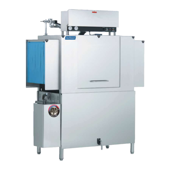
- Page 1 INSTALLATION, OPERATION, AND SERVICE MANUAL AJ SERIES CONVEYOR DISHMACHINES AJ-44 Series Manual • 07610-001-76-22-N...
- Page 2 ONE YEAR LIMITED PARTS AND LABOR WARRANTY For a period of one (1) year from date of original installation of a new Jackson Dishmachine (but in no event to exceed eighteen (18) months from date of shipment from Jackson’s factory), Jackson WWS, Inc. (Jackson) will repair or replace, at its discretion, any original part that proves defective in materials or workmanship at the time the Dishmachine was purchased;...
- Page 3 MANUFACTURER'S LIMITED WARRANTY (CONT.) (APPLICABLE ONLY IN THE UNITED STATES AND CANADA) PRODUCT CHANGES: Jackson reserves the right to make changes in design and specification of any component of the Dishmachine as engineering or necessity requires. DISCLAIMER OF WARRANTIES: THERE ARE NO WARRANTIES, EXPRESSED OR IMPLIED, INCLUDING, WITHOUT LIMITATION, ANY IMPLIED WARRANTY OF FITNESS FOR A PARTICULAR PURPOSE OR MERCHANTABILITY, THAT ARE NOT SET FORTH HEREIN, OR THAT EXTEND BEYOND THE DURATION HEREOF.
- Page 4 REVISION HISTORY Revision Revision Made by Applicable ECNs Details Letter Date 5-14-04 Added exhuast fan hook-up schematic. Updated installation instructions. Added three instruction sheets for limit 3-8-05 7096 switches. Added instruction sheet for curtain installation. Changed layout. 1-13-06 7470 Added service kits and maintenance instructions. 1-26-06 7600 Added gas exhaust fan schematic and component kits.
- Page 5 NOMENCLATURE AJ-44CGP, AJ-66CGP, AJ-80CGP Gas-heated, hot-water-sanitizing rack conveyor machines. The manufacturer provides technical support for all of the machines detailed in this manual. We strongly recommend that you refer to this manual before making a call to our technical support staff.
-
Page 6: Table Of Contents
TABLE OF CONTENTS GUIDES Symbols ............................1 Abbreviations & Acronyms ......................1 SPECIFICATIONS AJ-44 Dimensions........................2 AJ-66 Dimensions........................4 AJ-80 Dimensions........................6 Side-loader Dimensions......................8 Side-loader & Table Install ......................10 Operating Parameters ......................11 Electrical Requirements ......................12 INSTALLATION Installation Instructions ......................13 Inspection........................13 Unpacking ........................13 Leveling.......................... - Page 7 TABLE OF CONTENTS MAINTENANCE Preventative Maintenance ......................26 Torque Settings ........................26 Drive Gear Reducer Lubrication ....................27 TROUBLESHOOTING Troubleshooting ........................29 PARTS AJ-44 Control Box........................31 AJ-66/80 Control Box........................ 33 Motor Overloads ........................35 Frame/Panel ..........................36 Plumbing Options ........................37 Pre-wash Plumbing........................
- Page 8 TABLE OF CONTENTS PARTS Miscellaneous Parts ......................73 Go Box ..........................75 SCHEMATICS AJ-44CGP 208-230 V/60 Hz/1-Phase ......................76 208-230 V/60 Hz/3-Phase ......................77 460 V/60 Hz/3-Phase........................ 78 AJ-66CGP 208-230 V/60 Hz/1-Phase ......................79 208-230 V/60 Hz/3-Phase ......................80 380-460-600 V/60 Hz/3-Phase ....................81 Exhaust Fan..........................
-
Page 9: Symbols
GUIDES SYMBOLS - Risk of injury to personnel WARNING - Risk of damage to equipment CAUTION - Risk of electrical shock - Caustic chemicals - Reference data plate - Lockout electrical power - Important note NOTICE - Instructions Hyperlink ABBREVIATIONS &... -
Page 10: Specifications
AJ-44 DIMENSIONS SPECIFICATIONS Left-to-Right LEGEND 14 [355 mm] 6 [165 mm] 4 [102 mm] MIN A - Water Inlet (3/4" NPT, 110–140 °F MIN) B - Electrical Connection C - Drain Connection (1 1/2" NPT) D - Vent Collar - Optional E - Vent Cowl - Standard F - Water Inlet for Booster 21 [535 mm]... - Page 11 AJ-44 DIMENSIONS SPECIFICATIONS Right-to-Left LEGEND 6 [165 mm] 4 [102 mm] MIN 14 [355 mm] MIN A - Water Inlet (3/4" NPT, 110–140 °F MIN) B - Electrical Connection C - Drain Connection (1 1/2" NPT) D - Vent Collar - Optional E - Vent Cowl - Standard 21 [535 mm] F - Water Inlet for Booster...
-
Page 12: Dimensions
AJ-66 DIMENSIONS SPECIFICATIONS Left-to-Right 14 [355 mm] 6 [165 mm] LEGEND 5 [127 mm] 4 [102 mm] MIN A - Water Inlet (3/4" NPT, 110–140 °F MIN) B - Electrical Connection C - Drain Connection (1 1/2" NPT) D - Vent Collar - Optional E - Vent Cowl - Standard 21 [535 mm] F - Water Inlet for Booster... - Page 13 AJ-66 DIMENSIONS SPECIFICATIONS Right-to-Left 14 [355 mm] MIN 6 [165 mm] 4 [102 mm] MIN 5 [127 mm] LEGEND A - Water Inlet (3/4" NPT, 110–140 °F MIN) B - Electrical Connection C - Drain Connection (1 1/2" NPT) D - Vent Collar - Optional E - Vent Cowl - Standard 21 [535 mm] F - Water Inlet for Booster...
-
Page 14: Aj-80 Dimensions
AJ-80 DIMENSIONS SPECIFICATIONS Left-to-Right LEGEND 6 [165 mm] 14 [355 mm] 5 [127 mm] 4 [102 mm] MIN A - Water Inlet (3/4" NPT, 110–140 °F MIN) B - Electrical Connection C - Drain Connection (1 1/2" NPT) D - Vent Collar - Optional E - Vent Cowl - Standard F - Water Inlet for Booster 21 [535 mm]... - Page 15 AJ-80 DIMENSIONS SPECIFICATIONS Right-to-Left 14 [355 mm] MIN 6 [165 mm] 4 [102 mm] MIN 5 [127 mm] LEGEND A - Water Inlet (3/4" NPT, 110–140 °F MIN) B - Electrical Connection C - Drain Connection (1 1/2" NPT) D - Vent Collar - Optional E - Vent Cowl - Standard 21 [533mm] F - Water Inlet for Booster...
-
Page 16: Side-Loader Dimensions
SIDE-LOADER DIMENSIONS SPECIFICATIONS Left-to-Right 25” 4 1/2” 5” Minimum Dishmachine 12 1/2” Dishmachine Center-line Vent Connection Opening Conveyor Dishmachine Splash Shield 1 1/2” drain, connected 14 1/2” to dishmachine drain line. 29” Section A-A 1/2” Dishtable Minimum Use silicone between table and lip of side-loader Wall of side-loader... - Page 17 Dishmachine SIDE-LOADER DIMENSIONS SPECIFICATIONS Center-line Vent Connection Opening Right-to-Left Conveyor 25” 4 1/2” 5” Dishmachine Minimum Dishmachine 12 1/2” Splash Shield Dishmachine Center-line Vent Connection Opening Conveyor Dishmachine Splash Shield 14 1/2” 1 1/2” drain, connected to 29” 14 1/2” dishmachine drain line.
-
Page 18: Side-Loader & Table Install
SIDE-LOADER & TABLE INSTALL SPECIFICATIONS Side-loader Install 23” SIDE-LOADER DIMENSIONS 30” SIDE-LOADER DIMENSIONS MODEL DIMENSIONS MODEL DIMENSIONS AJ-44 75” AJ-44 82” 97” AJ-66 AJ-66 104” AJ-80 111” AJ-80 118” Left-to-Right shown. [254 mm] [102 mm] [864 mm] 23 or 30 [584 or 762 mm] Depending on the width of the side-loader. -
Page 19: Operating Parameters
OPERATING PARAMETERS SPECIFICATIONS OPERATING SPECIFICATIONS WATER REQUIREMENTS AJ-44/66/80 AJ-44/66/80 Racks per Hour Minimum Wash Temperature (°F/°C) 150/66 Dishes per Hour 6200 Minimum Power Rinse Temperature (°F/°C) 160/71 Glasses per Hour 8928 Minimum Rinse Temperature (°F/°C) 180/82 Pre-wash Temperature (°F/°C) 110–140/43–60 Pre-wash Flow Pressure (PSI) 20 ±... -
Page 20: Electrical Requirements
ELECTRICAL REQUIREMENTS SPECIFICATIONS All electrical ratings provided in this manual are for reference only. Always refer to the machine data plate to get the exact electrical information for this machine. All electrical work performed on machines should be done in accordance with applicable local, state, territorial, and national codes. -
Page 21: Installation Instructions
INSTRUCTIONS INSTALLATION INSPECTION Before installing the machine, check the packaging and machine for damage. Damaged packaging indicates possible damage to the machine. If there is any type of damage to both the packaging and machine, DO NOT THROW AWAY THE PACKAGING. The machine has been inspected at the factory and is expected to arrive in new, undamaged Do not throw away condition. -
Page 22: Plumbing
INSTRUCTIONS INSTALLATION PLUMBING All plumbing connections must adhere to local, state, territorial, and national codes. The installing plumber is responsible for ensuring the incoming water lines are flushed of debris before connecting the machine. Chips and materials from cutting processes can become The plumber MUST flush the incoming water line! lodged in the solenoid valves and prevent them from opening or closing. -
Page 23: Electrical Power Connections
INSTRUCTIONS INSTALLATION ELECTRICAL All electrical connections must be made in accordance with applicable portions of local, state, territorial, and national codes. POWER CONNECTIONS Refer to the data plate for machine operating requirements, machine voltage, total amperage, and serial number. 1. Locate main power terminal blocks (for machine and gas booster) at the top of the machine. -
Page 24: Motor Rotation
INSTRUCTIONS INSTALLATION MOTOR On 3-Phase machines only, correct pump motor rotation must be verified before the machine is operated. Failure to do so can result in damage to the machine and ROTATION components. 1. Follow the Power Up section. CAUTION CAUTION! On 3-Phase machines only, correct pump... -
Page 25: Chemical Feeder Equipment
INSTRUCTIONS INSTALLATION CHEMICAL FEEDER This machine does not come with an integrated chemical supply/feeder system. For the machine to operate correctly, connect it to a third-party chemical dispenser (see EQUIPMENT Connection Points section) that meets the requirements of NSF Standard 29. Contact a chemical supplier about connecting a dispenser to the machine. -
Page 26: Exhaust Fan Timer
INSTRUCTIONS INSTALLATION CONNECTION POINTS Incoming Water Rinse-aid Rinse-aid tube connection shown to the right. GRND Terminals marked "CVS" provide a voltage signal whenever the drive motor is operating. Terminals marked "DET" provide a voltage signal whenever the wash motor is operating. There is no dedicated connection for a rinse- aid dispenser on the... -
Page 27: Curtains
CURTAINS INSTALLATION Decals mark the curtain locations inside the machine, starting at the load end and ending at the unload end. The illustrations below (Left-to-Right machines shown, Right-to-Left are mirrored) indicate the curtain size to be placed on the curtain hooks provided. If any curtain components are missing, they MUST be obtained and installed before operation. CE &... -
Page 28: Hose Installation
HOSE INSTALLATION INSTALLATION The hosing connecting the gas booster to the machine must be customized during each installation. The appropriate 3/4" hosing, fittings, and gaskets are provided. Additional hosing can be ordered from the manufacturer, if necessary. Placing the gas booster more than 20 feet from the machine can affect performance. 1. -
Page 29: Operation
OPERATING INSTRUCTIONS OPERATION PREPARATION Before operating the machine, verify the following: 1. Drain handle is turned to “CLOSE” position. OPEN CLOSE 2. Strainers and pawl bar are installed and secure. 3. Actuator switches move with relative freedom and do not bind. 4. -
Page 30: First Rack
OPERATING INSTRUCTIONS OPERATION FIRST RACK The first rack of ware placed in the machine will typically reduce the temperature of the wash tank, and might need to run through the machine again. This process might be necessary any time the machine has not been operated for an extended period of time, although this is dependent on the type of ware being used, its temperature, and the... -
Page 31: Shutdown
OPERATING INSTRUCTIONS OPERATION SHUTDOWN To shut the machine down, press the OFF button on the front of the machine. To drain the machine, move the drain handle to the OPEN position. Shut down gas booster according to its manufacturer’s instructions. CLEANING Clean the machine at least once every 24 hours or at the end of the day. - Page 32 OPERATING INSTRUCTIONS OPERATION CLEANING 5. As needed, clean the wash and rinse arms: a. Remove wash arm manifolds. For machines with pre-wash sections, also remove and clean the pre-wash arm. b. Remove end-caps from arms and manifolds. c. Clean nozzles with a brush. Also clean rinse assembly nozzles. d.
-
Page 33: Deliming
OPERATING INSTRUCTIONS OPERATION DELIMING 1. Disconnect/turn off chemical feeder equipment. 2. Turn the machine on. GRND 3. Add deliming solution according to chemical supplier’s instructions. 4. Close door. 5. Flip AUTOMATIC/DELIME switch to DELIME. 6. Run the machine period of time recommended by chemical supplier. 7. -
Page 34: Preventative Maintenance
PREVENTATIVE MAINTENANCE MAINTENANCE PREVENTATIVE The manufacturer highly recommends that any maintenance and repairs not specifically discussed in this manual be performed only by QUALIFIED SERVICE PERSONNEL. MAINTENANCE Performing maintenance on your machine may void your warranty, lead to larger problems, or even cause harm to the operator. -
Page 35: Drive Gear Reducer Lubrication
PREVENTATIVE MAINTENANCE LUBRICANTS MAINTENANCE WORM GEAR REDUCERS DRIVE GEAR The maintenance procedures detailed here are manufacturer’s instructions for the brand of gear reducer that is installed on the machines covered in this manual. REDUCER For special applications that involve severe ambient experience, recommends the use of Mobil SHC temperature extremes or a seasonal oil requirement, synthetic lubricants. - Page 36 PREVENTATIVE MAINTENANCE MAINTENANCE DRIVE GEAR after a short period of operation and adjusted, if necessary. When changing double- reduction models, each housing should be drained and filled independently, even though REDUCER there could be a common level. LUBRICATION Initial oil change - The new oil in a speed reducer should be changed at the end of 250 hours of operation.
-
Page 37: Troubleshooting
TROUBLESHOOTING TROUBLESHOOTING WARNING: Inspection, testing, and repair of electrical equipment should only be performed by a qualified service technician. Many of the tests require that the machine have power to it and live electrical components be exposed. USE EXTREME CAUTION WHEN TESTING THE MACHINE. WARNING OBSERVATION POSSIBLE CAUSE... - Page 38 TROUBLESHOOTING TROUBLESHOOTING WARNING: Inspection, testing, and repair of electrical equipment should only be performed by a qualified service technician. Many of the tests require that the machine have power to it and live electrical components be exposed. USE EXTREME CAUTION WHEN TESTING THE MACHINE. WARNING OBSERVATION POSSIBLE CAUSE...
-
Page 39: Parts
AJ-44 CONTROL BOX PARTS GRND ITEM DESCRIPTION PART NUMBER Electrical Box 05700-041-88-50 Decal, L1-L2-L3 09905-004-37-05 Terminal Block 05940-011-48-27 Lockwasher, #10 05311-273-02-00 Screw, 10-32 x 3/4” Phillips Trusshead 05305-011-62-17 Wire Lug, 2 AWG to 14 AWG 05940-200-76-00 Light, Red (Power) 05945-111-44-45 Din Rail 05700-021-72-75 Screw, 10-32 x 1/2”... - Page 40 AJ-44 CONTROL BOX PARTS ITEM DESCRIPTION PART NUMBER Drive Motor Contactor 05945-111-68-38 Wash Pump Motor Contactor 05945-111-68-38 Circuit Breaker (208-230 V, 60 Hz Models Only) 05925-011-68-34 Wash Pump Motor Overload See Motor Overloads page. Switch, ON/FILL - OFF/DRAIN 05930-011-49-55 Drive Motor Overload See Motor Overloads page.
-
Page 41: Aj-66/80 Control Box
AJ-66/80 CONTROL BOX PARTS GRND ITEM DESCRIPTION PART NUMBER Electrical Box 05700-041-88-50 Decal, L1-L2-L3 09905-004-37-05 Terminal Block 05940-011-48-27 Lockwasher, #10 05311-273-02-00 Screw, 10-32 x 3/4” Phillips Trusshead 05305-011-62-17 Wire Lug, 2 AWG to 14 AWG 05940-200-76-00 Light, Red (Power) 05945-111-44-45 Din Rail 05700-021-94-96 Screw, 10-32 x 1/2”... - Page 42 AJ-66/80 CONTROL BOX PARTS ITEM DESCRIPTION PART NUMBER Switch, ON/FILL - OFF/DRAIN 05930-011-49-55 Drive Motor Overload See Motor Overloads page. Terminal Board 05940-021-89-41 Transformer 05950-002-46-10 Locknut, 10-24 with Nylon Insert 05310-373-01-00 Fuse Holder (460 V Only) 05920-011-72-89 Fuse (460 V Only) 05920-011-72-88 Screw, 6-32 x 3/8”...
-
Page 43: Motor Overloads
MOTOR OVERLOADS PARTS AJ-44 VOLTS PHASE DRIVE MOTOR PRE-WASH MOTOR WASH MOTOR POWER RINSE MOTOR 05945-111-68-39 05945-111-68-40 05945-111-68-40 05945-111-68-39 05945-111-68-40 05945-111-68-40 05945-111-69-12 05945-111-68-41 05945-111-68-41 AJ-66 VOLTS PHASE DRIVE MOTOR PRE-WASH MOTOR WASH MOTOR POWER RINSE MOTOR 05945-111-68-39 05945-111-68-41 05945-111-68-40 05945-111-68-40 05945-111-68-39 05945-111-68-41 05945-111-68-40... -
Page 44: Frame/Panel
FRAME/PANEL PARTS ITEM DESCRIPTION PART NUMBER Frame Weldment (AJ-44) 05700-002-52-70 Frame Weldment (AJ-66 L-R) 05700-002-49-28 Frame Weldment (AJ-66 R-L) 05700-002-57-57 Front Dress Panel (AJ-44) 05700-002-52-77 Front Dress Panel (AJ-66 L-R) 05700-002-51-22 Front Dress Panel (AJ-66 R-L) 05700-002-57-84 Adjustable Foot 05340-011-71-74 07610-001-76-22-N... -
Page 45: Plumbing Options
PLUMBING OPTIONS PARTS SHOCK ABSORBER (WATER ARRESTOR) OPTION Water Arrestor, 1/2” 06685-100-05-00 Tee, 3/4” x 3/4” x 1/2” 04730-211-06-00 Nipple, 3/4”, Close, Brass 04730-207-34-00 WATER TREATMENT OPTION Scaltrol System Replacement Cartridge 04730-003-05-76 (inspect at least every 6 months) RSC-100 07610-001-76-22-N... -
Page 46: Pre-Wash Plumbing
PRE-WASH PLUMBING PARTS Complete Pre-wash Plumbing Assembly 05700-031-74-83 ITEM DESCRIPTION PART NUMBER Fill Line Injector 05700-011-67-99 Gasket, Fill Line Injector 05330-111-42-81 Nipple, 3/4" x 6" 05700-001-26-74 Elbow, 90-degree, Brass, 3/4” 04730-206-04-34 Vacuum Breaker, 3/4" 04820-002-53-77 Valve, Solenoid, 3/4” 04730-100-53-00 Nipple, Brass, Close, 3/4" 04730-207-34-00 Y-strainer, 3/4”... -
Page 47: Plumbing
PLUMBING PARTS Complete Plumbing Assembly 05700-002-51-17 07610-001-76-22-N... - Page 48 PLUMBING PARTS ITEM DESCRIPTION PART NUMBER Kit, Rinse Injector 05700-002-57-87 Gasket, Injector 05330-111-42-81 Plug, 1/8”, Brass 04730-209-07-37 Vacuum Breaker, Brass, 3/4” 04820-002-53-77 Valve, Solenoid, 3/4” 04810-100-53-00 Elbow, 90-degree, Brass, 3/4” 04730-206-04-34 Nipple, Brass, 3/4" x 1 3/8" 04730-207-34-00 Union, Brass, 3/4" 04730-212-05-00 Adapter, Female, 3/4"...
-
Page 49: Rinse Header Plumbing
RINSE HEADER PLUMBING PARTS Complete Rinse Header Plumbing Assembly 05700-002-51-16 ITEM DESCRIPTION PART NUMBER Y-strainer, Brass, 3/4" 04730-717-02-06 Nipple, Brass, 3/4" 04730-207-34-00 Pressure Regulator, 3/4” 04820-002-51-53 Bracket, Plumbing Support 05700-002-50-70 Valve, Solenoid, 3/4” 04810-100-53-00 Incoming Piping Assembly 05700-002-51-15 Bracket, Inlet Plumbing Mounting 05700-002-51-41 Clamp, Pipe 05700-000-35-06... -
Page 50: Wash Tank Coil
WASH TANK COIL PARTS Complete Coil Assembly, L-R 05700-041-88-31 ITEM DESCRIPTION PART NUMBER Coil 05700-031-88-30 Stand "A" 05700-002-74-82 Stand "C" 05700-002-74-84 Coil Gasket 05700-001-17-86 Flat Washer 05700-001-17-87 Coil Nut 05310-011-17-85 Complete Coil Assembly, R-L 05700-002-81-44 ITEM DESCRIPTION PART NUMBER Coil 05700-031-88-30 Stand "A"... -
Page 51: Coil Assembly
COIL ASSEMBLY PARTS See previous page. See Gas System Connections page . Coil Box 05700-002-50-94 Coil Box Cover 05700-002-48-50 Items Not Shown: ITEM DESCRIPTION PART NUMBER Thermostat, High-Limit 05930-011-49-43 Gasket 05330-200-02-70 Terminal Board 05940-002-78-97 Thermostat Bracket 05700-011-81-64 Decal, Thermostat Regulating 09905-011-84-31 Thermostat, Wash Regulating 06401-140-00-32... -
Page 52: Tank Assembly
TANK ASSEMBLY PARTS Complete Tank Assembly 05700-002-45-05 Bottom Angled View Top Angled View ITEM DESCRIPTION PART NUMBER Plumbing Assembly, Rinse Tank 05700-002-51-24 Tube, Dispersion 05700-002-46-16 Tank, Rinse 05700-002-45-05 Bracket, Upper Rinse Tank 05700-002-67-13 Bracket, Lower Rinse Tank 05700-002-67-14 Nipple, 3/4" x 4" 04730-207-05-00 Elbow, 90-degree, Brass, 3/4"... -
Page 53: Recirculating Pump
RECIRCULATING PUMP PARTS Complete Recirculating Pump Assembly 05700-002-51-29 (Does not include bracket.) ITEM DESCRIPTION PART NUMBER Nipple, Brass, 3/4" 04730-207-34-00 Elbow, 90-degree, Brass, 3/4" 04730-206-13-00 Pump, Recirculating 06105-002-05-26 Pump, Recirculating Modified 05700-002-81-22 Pump, Recirculating with Adapters 05700-002-51-28 Bracket, Mounting (AJ-66 L-R) 05700-002-25-74 Bracket, Mounting (All Other Models) 05700-004-61-85... -
Page 54: System Connections
SYSTEM CONNECTIONS PARTS ITEM DESCRIPTION AJ-44 AJ-66/80 Hose, Recirculating Discharge 05700-002-52-74 05700-002-52-76 Hose, Recirculating Pump Suction 05700-002-52-75 05700-002-51-38 Hose, Wash Coil Assembly 05700-002-52-76 04720-011-94-10 Hose, Wash/Fill Supply 05700-003-03-97 05700-003-03-99 Connection, Hose to Gas Booster Outlet Connection, Hose to Gas Booster Inlet Hose, Coil Recirculating 05700-002-17-71 05700-002-17-71... -
Page 55: Aj-44 Drain Plumbing
AJ-44 DRAIN PLUMBING PARTS Complete AJ-44 Drain Plumbing Assembly 05700-002-52-71 ITEM DESCRIPTION PART NUMBER Valve, Ball, 1 1/2” 04820-111-71-46 Ball Valve Handle Assembly 05700-021-84-74 Spacer (Not Shown) 05700-002-87-05 Elbow, 90-degree, Street Brass, 1 1/2" 04730-206-32-00 Nipple, Brass, 1 1/2” 04730-207-40-00 Cross Connector, 1 1/2"... -
Page 56: Aj-66 Drain Plumbing, L-R
AJ-66 DRAIN PLUMBING, L-R PARTS Complete AJ-66 Drain Plumbing Assembly, L-R 05700-002-50-95 ITEM DESCRIPTION PART NUMBER Adapter, 1 1/2" 04730-401-25-01 Connector, No-hub, 1 1/2” 04720-003-73-73 Tee, Brass, 1 1/2” 04730-011-69-93 Ball Valve, 1 1/2” 04820-011-71-46 Nipple, Close Brass, 1 1/2” 04730-207-40-00 Elbow, Brass, 90-degree, 1 1/2”... -
Page 57: Aj-66 Drain Plumbing, R-L
AJ-66 DRAIN PLUMBING, R-L PARTS Complete AJ-66 Drain Plumbing Assembly, R-L 05700-002-57-59 ITEM DESCRIPTION PART NUMBER Elbow, 1 1/2”, Street Brass 04730-206-32-00 Ball Valve, 1 1/2” 04820-011-71-46 Adapter, 1 1/2" 04730-401-25-01 Tube, Copper, 1 1/2” x 1 7/8" See note below. Tee, Brass, 1 1/2”... -
Page 58: Solenoid Valve & Vacuum Breaker
SOLENOID VALVE & VACUUM BREAKER PARTS Complete 110 V Valve Assembly, 3/4" Complete Vacuum Breaker Assembly, 3/4" 04810-100-53-00 04820-002-53-77 Coil & Housing Only 04810-200-01-18 Screw Cap Screw Data Plate Coil & Housing Data Plate Valve Bonnet Spring 06401-003-07-40 Spring & Plunger 06401-003-07-40 Plunger Cap Retainer... -
Page 59: Drain Water Tempering Kit
DRAIN WATER TEMPERING KIT PARTS Drain Water Tempering Kit 06401-002-44-07 To Cold Water Supply To Machine Drain To Facility Drain From the existing drain, attach the two additional Tees (Item 7) using the 1 1/2” Close Brass Nipples (Item 8). Tighten the Reducers (Items 6 and 9) into the Tees as shown above. -
Page 60: Motor
MOTOR PARTS ITEM DESCRIPTION PART NUMBER Motor See table on the next page. Key, 3/16” x 1” 05700-011-89-17 Pump Plate 05700-021-71-83 Pump Seal 05330-011-71-98 Wash Impeller 05700-031-67-45 Power Rinse Impeller (AJ-80) 05700-031-67-45 05700-031-71-78 Pre-wash Impeller (AJ-66/80) Impeller Washer 05700-011-71-95 Bolt, Hex Head 1/4-20 x 3/4” 05305-004-42-64 Upper Support Bracket 05700-021-73-68... - Page 61 MOTOR PARTS WASH MOTORS Volts Phase Motor Part Number Complete Kit Part Number 208-230 06105-021-70-57 06401-003-09-97 208-230 06105-121-70-58 06401-003-09-98 06105-121-70-58 06401-003-09-98 PRE-WASH MOTORS AJ-66 Volts Phase Motor Part Number Complete Kit Part Number 208-230 06105-121-70-55 06401-003-10-40 200-230 06105-121-70-56 06401-003-10-38 06105-121-70-56 06401-003-10-38 07610-001-76-22-N...
-
Page 62: Pre-Wash & Wash Pumps
PRE-WASH & WASH PUMPS PARTS Parts are not shown to scale with relation to each other. ITEM DESCRIPTION PART NUMBER Pre-wash Strainer Bracket 05700-021-74-94 Pre-wash Intake Strainer 05700-021-74-96 Intake Suction Scoop 05700-021-87-60 Power Rinse Pump Weldment (AJ-80) 05700-031-81-47 Wash Pump Weldment (All Models) 05700-041-68-88 Pre-wash Pump Weldment (AJ-66/80 L-R) 05700-002-10-62... -
Page 63: Pre-Wash & Upper Wash Arm
PRE-WASH & UPPER WASH ARM PARTS Complete Pre-wash Arm Assembly Complete Upper Arm Assembly 05700-021-74-65 05700-031-74-99 ITEM DESCRIPTION PART NUMBER End-cap 05700-011-67-11 End-cap Replacement Kit* 06401-003-10-19* Pre-wash Tube (AJ-66/80) 05700-001-16-89 Pre-wash Manifold (AJ-66/80) 05700-031-69-70 Mounting Screw, End-cap, 10-32 x 3/8" 05305-173-12-00 Lanyard 05340-011-72-46... -
Page 64: Lower Wash Arm
LOWER WASH ARM PARTS Complete Lower Wash Arm Assembly 05700-031-74-66 ITEM DESCRIPTION PART NUMBER Lower Wash Arm 05700-031-67-29 End-cap 05700-011-67-11 End-cap Kit* 06401-003-10-19* Manifold Quick-Release Key 05700-011-94-45 Lanyard 05340-011-72-46 Mounting Screw, End-cap, 10-32 x 3/8" 05305-173-12-00 Bracket, Lower Wash Arm Support (Not Shown) 05700-011-71-20 Locknut, 1/4-20 with Nylon Insert (Not Shown) 05310-374-01-00... -
Page 65: Final Rinse
FINAL RINSE PARTS * Kits contain rinse arm, end- caps, o-rings, and retaining rings. ITEM DESCRIPTION PART NUMBER Rinse Arm Support Bracket 05700-011-71-19 Gasket, Final Rinse Manifold 05330-111-42-81 Upper Rinse Arm Kit 06401-003-10-08 End-cap 04730-209-07-37 Rinse Nozzle 04730-003-59-63 Final Rinse Manifold 05700-031-74-88 Rinse Pan Strainer 05700-041-85-09... -
Page 66: Doors
DOORS PARTS Parts are not shown to scale with relation to each other. ITEM DESCRIPTION PART NUMBER Door (Emboss) 05700-031-83-39 Door (No Emboss) 05700-003-13-53 Pre-wash Door, Left-to-Right (Emboss) 05700-031-95-05 Pre-wash Door, Left-to-Right (No Emboss) 05700-003-13-42 Pre-wash Door, Right-to-Left (Emboss) 05700-031-95-07 Pre-wash Door, Right-to-Left (No Emboss) 05700-003-13-40 Screw, 8-32 x 1/4”... -
Page 67: Drive Assembly
DRIVE ASSEMBLY PARTS Complete Drive Assembly 05700-041-67-38 ITEM DESCRIPTION PART NUMBER Mounting Bracket Drive Motor 05700-031-73-56 Drive Plate and Rod 05700-021-67-44 Adjuster, Handle 05700-021-72-28 Coupling & Expansion Legs 05700-021-67-50 Adjuster, Crank Assembly 05700-021-69-95 Adjuster, Scotch Yoke 05700-021-69-76 Lockwasher, 3/8” 05311-276-01-00 Flat Washer, 3/8”... - Page 68 DRIVE ASSEMBLY PARTS ITEM DESCRIPTION PART NUMBER Bearing, Roller 03120-011-71-81 Collar, Shaft Conveyor Drive 05700-011-89-18 Bolt, 3/8-16 x 1 3/4” 05306-011-36-94 Spring, Adjuster 05315-011-71-90 Nut, Hex, 3/8-16 05310-276-01-00 Set Screw, 5/16-18 x 1/4" 05305-002-98-39 Bolt, 3/8-16 x 3/4” 05306-011-71-60 Drive Motor, 3-phase Machines 06105-121-70-54 Drive Motor, 1-phase Machines 06105-021-70-53...
-
Page 69: Pawl Bar Roller Bracket
PAWL BAR ROLLER BRACKET PARTS Parts are not shown to scale with relation to each other. ITEM DESCRIPTION PART NUMBER Pawl Bar Bracket (No Tabs) 05700-031-92-36 Pawl Bar Roller Kit* 06401-003-11-80 Pawl Bar Bracket (Tabs) 05700-031-84-68 Top Guide Block 05700-011-69-49 06401-003-10-15 Guide Block Kit* Pawl Bar Gutter Gasket... -
Page 70: Pawl Bars
PAWL BARS PARTS Complete AJ-44 Pawl Bar Assembly with Hardware 06401-131-81-00 06401-231-81-00 (Prison) Complete AJ-66 Pawl Bar Assembly with Hardware 06401-141-74-64 06401-241-74-64 (Prison) Complete AJ-80 Pawl Bar Assembly with Hardware 06401-141-81-06 (L-R) 06401-241-81-06 (L-R) 06401-341-81-06 (Prison) NOTICE When replacing rack catches, ensure to re-install in the appropriate direction. -
Page 71: Aj-44 Rack Rails
AJ-44 RACK RAILS PARTS ITEM DESCRIPTION PART NUMBER Rack Rail 05700-031-67-59 05700-031-69-48 Opposite Rack Rail Actuator Switch 05700-021-72-39 Actuator Switch Replacement Kit 06401-003-10-14 Bolt, Hex Head 1/4-20 x 3/4" 05305-004-42-64 Pawl Bar Spacer 05700-011-71-44 Locknut, 1/4-20 Hex with Nylon Insert 05310-374-01-00 Kit contains the switch, two spacers, and hardware. -
Page 72: Rack Rails
AJ-66 RACK RAILS PARTS Left-to-Right Right-to-Left 07610-001-76-22-N... - Page 73 AJ-66 RACK RAILS PARTS ITEM DESCRIPTION PART NUMBER Large Actuator Switch, L-R 05700-021-76-97 Large Actuator Switch Replacement Kit, L-R 06401-003-10-99 Large Actuator Switch, R-L 05700-002-91-09 06401-003-10-86 Large Actuator Switch Replacement Kit, R-L 8 per rail Bolt, Hex Head 1/4-20 x 3/4" 05305-004-42-64 8 per rail Locknut, 1/4-20 Hex with Nylon Insert...
-
Page 74: Rinse Fill Option
RINSE FILL OPTION PARTS Complete Rinse Fill Motor Assembly 05700-002-40-25 ITEM DESCRIPTION PART NUMBER Motor 06105-002-72-71 Bracket, Pump Mounting 05700-003-17-56 Clamp, Hose 5 5/8” to 6” 04730-011-34-90 Reducer Bushing, 1 1/4” to 1” 04730-002-73-62 Reducer Bushing 1” to 3/4” 04730-011-65-14 Elbow, 90-Degree, Street Brass, 1”... -
Page 75: Strainers
STRAINERS PARTS Parts are not shown to scale with relation to each other. ITEM DESCRIPTION PART NUMBER Front Strainer 05700-021-85-10 Back Strainer 05700-021-85-11 Overflow Strainer Support 05700-001-96-48 Drain Guard Strainer 05700-002-09-15 Wash Intake Strainer 05700-002-51-52 Tub Strainer 05700-002-03-21 Screen Strainer with Handle 05700-002-09-04 Wash Strainer Separator 05700-031-84-38... -
Page 76: Manifolds
MANIFOLDS PARTS Parts are not shown to scale with relation to each other. ITEM DESCRIPTION PART NUMBER Manifold, Pre-wash (AJ-66) 05700-031-69-70 05700-002-24-94 Manifold, Pre-wash (AJ-80) Manifold, Wash 05700-031-71-13 Washer, Flat, 1/4" (Not Shown) 05311-174-01-00 05310-374-01-00 Locknut, 1/4-20 with Nylon Insert (Not Shown) Shoulder Bolt Wingnut 05700-002-46-02 Fill Tube, Wash... -
Page 77: Float Switch/Scrap Basket
FLOAT SWITCH/SCRAP BASKET PARTS Parts are not shown to scale with relation to each other. ITEM DESCRIPTION PART NUMBER Float Switch Support Bracket Kit* 06401-003-11-77 Float Switch Cover 05700-021-75-71 Wash Tank Float Switch Kit* 06401-003-11-75 06401-003-11-76 Pre-wash Tank Float Switch Kit* Scrap Basket Lid 05700-002-56-55 Scrap Basket Assembly... -
Page 78: Curtains/Conveyor Switch
CURTAINS/CONVEYOR SWITCH PARTS Parts are not shown to scale with relation to each other. 24.5 ITEM DESCRIPTION PART NUMBER Curtain, XL, 24 1/2” x 20 1/2” 08415-002-47-37 Curtain, L, 21” x 20 1/2” 08415-131-73-45 Curtain, S, 12” x 20 1/2” 08415-131-73-44 Decal, XL Curtain 09905-004-38-08... -
Page 79: Side-Loader Parts
SIDE-LOADER PARTS PARTS Parts are not shown to scale with relation to each other. 07610-001-76-22-N... - Page 80 SIDE-LOADER PARTS PARTS ITEM DESCRIPTION PART NUMBER Actuator Switch, Side-loader 05700-002-91-12 Actuator Switch Kit* 06401-003-10-64 Pawl Bar Spacer 05700-011-71-44 Track, Side-loader (L-R), 23” 05700-031-78-98 Track, Side-loader (R-L), 23” 05700-031-95-20 Track, Side-loader (L-R), 30” 05700-003-04-57 Track, Side-loader(R-L), 30” 05700-003-04-58 Adjustable Foot, Side-loader 05340-108-01-03 Leg Socket Kit* 06401-003-09-79...
-
Page 81: Miscellaneous Parts
MISCELLANEOUS PARTS PARTS Parts are not shown to scale with relation to each other. ITEM DESCRIPTION PART NUMBER Vent Cowl 05700-041-86-94 Vent Cowl Cover 05700-011-74-67 Vent Cowl Cover Replacement Kit* 06401-003-10-16 Gasket, Top Vent Cowl 05330-031-83-47 Gasket, Side Vent Cowl 05330-031-83-48 Vent Scoop Option 05700-002-04-08... - Page 82 MISCELLANEOUS PARTS PARTS Parts are not shown to scale with relation to each other. ITEM DESCRIPTION PART NUMBER Plate, Left Water Directional 05700-021-79-27 Plate, Right Water Directional 05700-021-79-23 Run-off Sheet 05700-021-71-39 Splash Shield 05700-031-85-16 Hole Direction Plate Kit* 06401-003-10-00 Rinse Drain Plate Gasket 05330-011-72-27 Pipe Clamp 05700-000-35-05...
-
Page 83: Go Box
GO BOX PARTS The Go Box is a kit of the most-needed parts to successfully complete a repair in the first call, 90% or more of the time. Go Box Kit 06401-002-14-99 DESCRIPTION PART NUMBER Contactor, Drive Motor 05945-111-68-38 Contactor, Wash Heater, 3-phase, 3-pole 05945-002-24-70 Contactor, Wash Heater, 1-phase, 4-pole 05945-111-68-37... -
Page 84: Schematics
AJ-44CGP 208-230 V/60 HZ/1-PHASE SCHEMATICS AJ-44CGP SCHEMATIC 07610-001-76-22-N... -
Page 85: 208-230 V/60 Hz/3-Phase
AJ-44CGP 208-230 V/60 HZ/3-PHASE SCHEMATICS AJ-44CGP SCHEMATIC 07610-001-76-22-N... -
Page 86: 460 V/60 Hz/3-Phase
AJ-44CGP 460 V/60 HZ/3-PHASE SCHEMATICS AJ-44CGP SCHEMATIC 07610-001-76-22-N... -
Page 87: Aj-66Cgp
AJ-66CGP 208-230 V/60 HZ/1-PHASE SCHEMATICS AJ-66CGP SCHEMATIC 07610-001-76-22-N... -
Page 88: 208-230 V/60 Hz/3-Phase
AJ-66CGP 208-230 V/60 HZ/3-PHASE SCHEMATICS AJ-66CGP SCHEMATIC 07610-001-76-22-N... -
Page 89: 380-460-600 V/60 Hz/3-Phase
AJ-66CGP 380-460-600 V/60 HZ/3-PHASE SCHEMATICS AJ-66CGP SCHEMATIC 07610-001-76-22-N... -
Page 90: Exhaust Fan
EXHAUST FAN SCHEMATICS 07610-001-76-22-N... -
Page 91: Side-Loader
SIDE-LOADER SCHEMATICS 07610-001-76-22-N... - Page 92 Jackson WWS, Inc. • 6209 N. US Hwy 25E • Gray, KY 40734 USA 1.888.800.5672 • www.jacksonwws.com AJ-44 Series Manual • 07610-001-76-22-N...