Table of Contents
Advertisement
Quick Links
Advertisement
Table of Contents

Related Manuals for Viessmann MatriX radiant burner


Summary of Contents for Viessmann MatriX radiant burner
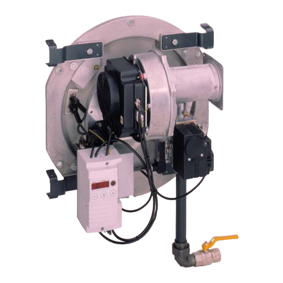
- Page 1 Service instructions for heating engineers MatriX radiant burner Pressure jet gas burner (type VM III) for Vitocrossal 300 (type CT3) Rated output 170 (187) kW See notes on applicability, page 2. MatriX radiant burner Please keep safe 5692 541 GB...
-
Page 2: General Information
(heating engineer/installation Use only original Viessmann spare contractor). parts, or equivalent parts that have been approved by Viessmann. Before working on the equipment/ heating system, isolate the mains Initial start−up... -
Page 3: Table Of Contents
Contents Index Page General information Safety instructions ........................Applicability . -
Page 4: Initial Start−Up, Inspection And Maintenance
Initial start−up, inspection and maintenance Steps initial start−up, inspection and maintenance For further instructions on individual steps, see pages indicated. Commissioning steps Inspection steps Maintenance steps Page 1. System start−up ................2. -
Page 5: Further Details Regarding The Individual Steps
Initial start−up, inspection and maintenance Further details regarding the individual steps ¨ Safety instructions Measure the CO value before and after any work on gas appliances, to prevent any health hazards and to ensure perfect system condition. Checking the burner adjustment with the boiler at operating temperature (min. -
Page 6: Checking Gas Type
Initial start−up, inspection and maintenance Further details regarding the individual steps (cont.) Checking gas type 1. Enquire the gas type and Wobbe index (Wo) from your gas supplier. H With natural gas setting E, the boiler can be operated in the Wobbe index range 12.0 to 16.1 kWh/m (43.2 to 58.0 MJ/m... -
Page 7: Conversion To Natural Gas Ll
Initial start−up, inspection and maintenance Further details regarding the individual steps (cont.) Conversion to natural gas LL 1. Close the gas shut−off valve. 2. Switch OFF the system ON/OFF switch on the control unit. 3. Switch OFF the mains electrical isolator (outside the installation room) or the mains power supply and prevent unauthorised... -
Page 8: Checking Static And Supply Pressure
Initial start−up, inspection and maintenance Further details regarding the individual steps (cont.) Checking static and supply pressure Static pressure 1. Close the gas shut−off valve. 2. Release the screw inside test nipple A, but do not fully remove. 3. Connect the U−shaped pressure gauge. - Page 9 Initial start−up, inspection and maintenance Further details regarding the individual steps (cont.) Supply pressure 7. Start up the burner. Please note: Initial start−up, see page 5. Switch the burner to max. output; to do this, activate the emissions test switch on the control unit. 8.
-
Page 10: Checking Venturi Vacuum Pressure
Initial start−up, inspection and maintenance Further details regarding the individual steps (cont.) Checking venturi vacuum pressure 5. Simultaneously press keys S D and C. Please note: Display B shows: H Status: d (= regular stop) and H Service: Level of modulation in % (00. -
Page 11: Checking Co Content
Initial start−up, inspection and maintenance Further details regarding the individual steps (cont.) Checking CO content 1. Open the gas shut−off valve. 2. Start up the burner. 3. Press keys S E and D simultaneously. Please note: Display C shows: H Status: d (= regular stop) and H Service: Level of modulation in % (00. - Page 12 Initial start−up, inspection and maintenance Further details regarding the individual steps (cont.) Partial load 7. Press key D, until the service display has decremented to 00 (partial load). 8. Measure the CO content at the flue pipe. The CO should be 8.8 to 9.3 %. 9.
-
Page 13: Checking Ionisation Current
Initial start−up, inspection and maintenance Further details regarding the individual steps (cont.) Checking ionisation current 6. Plug socket A of the test lead 1. Switch OFF the mains electrical isolator. onto the ionisation electrode. 2. Pull ionisation cable plug C off. 7. -
Page 14: System Shutdown
Initial start−up, inspection and maintenance Further details regarding the individual steps (cont.) System shutdown 2. Pull plug−connectors fA and lÖ off 1. Switch OFF the mains electric power or mains electrical isolator the burner. and safeguard against unauthorised reconnection. 3. Close the gas shut−off valve. Checking burner gauze assembly 1. -
Page 15: Checking Ignition And Ionisation Electrodes
Initial start−up, inspection and maintenance Further details regarding the individual steps (cont.) Checking ignition and ionisation electrodes Ignition electrodes 1. Check the ignition electrodes and the ionisation electrode for correct gap towards the burner gauze assembly and damage (replace, if necessary). -
Page 16: Cleaning Burner
Initial start−up, inspection and maintenance Further details regarding the individual steps (cont.) Cleaning burner 1. Release fixing C from gas supply pipe D. 2. Unscrew venturi mixing tube E from fan A. 3. Remove venturi mixing tube E with gas combination valve B and gas supply pipe D. -
Page 17: Checking Both Valves Of Gas Combination Valve For Leaks
3. Release the screw in test nipple A Otherwise, the system leaks. In but do not remove. this case, return the gas combination valve to Viessmann 4. Connect the U−shaped pressure Werke for tests. gauge with a manual pump to test nipple A. -
Page 18: Checking All Gas Unions For Leaks
Initial start−up, inspection and maintenance Further details regarding the individual steps (cont.) Checking all gas unions for leaks 1. Insert new gaskets in all fittings which have been opened, and tighten fittings. 2. Open the gas shut−off valve. 3. Check the inlet seals of the gas combination valve for leaks. -
Page 19: Burner Control Unit
Initial start−up, inspection and maintenance Gas burner control unit Display and programming unit Function A display and programming unit is The display comprises three, integrated into the burner control seven−segment elements; four keys unit. The display indicates the enable settings to be adjusted at respective operating conditions, the different operating levels. - Page 20 Initial start−up, inspection and maintenance Gas burner control unit (cont.) Display Status Service (1 digit) (two digits) Operating display in Current operating state Display FL if a Page 21 standard mode see following table flame signal is present Operating display for Message code A to L operation deviating see following table...
- Page 21 Initial start−up, inspection and maintenance Gas burner control unit (cont.) Operating display See also tables on page 20. Press the reset button Status Service Status Service Heat demand System tests Standby Status Service Idle state check Fan run−up Status Service Pre−purge Status Service Status Service...
- Page 22 Initial start−up, inspection and maintenance Gas burner control unit (cont.) Service display The service display can only be shown with the burner in operation, i.e. a heat demand from the control unit must be present. During the service display, the burner will not respond to output changes from the control unit (regular stop mode).
- Page 23 Initial start−up, inspection and maintenance Gas burner control unit (cont.) Setting the DIP switch or parameter set Setting Setting Rated burner output Reduced burner output Parameter set 3 Parameter set 8 ¢ 170 (187) kW ¢ 119 (131) kW Displaying the selected parameter set This display will be terminated, if no key is pressed within 20 seconds.
- Page 24 Initial start−up, inspection and maintenance Gas burner control unit (cont.) Confirming a parameter set H a parameter set has been modified via the DIP switch or H the burner control unit has been replaced, a flashing P appears below status. The figures below service indicate the selected parameter set (see page 25).
- Page 25 Initial start−up, inspection and maintenance Gas burner control unit (cont.) Fault display The fault display will be activated automatically if the burner control unit switches to a fault state. The last fault will then be displayed. The light segments of the display will flash. Operating display Automatic activation...
- Page 26 Initial start−up, inspection and maintenance Gas burner control unit (cont.) Fault memory The last six faults are saved and may be called up. The order of scans ranges from the last to the previous fault codes. The fault memory display will be terminated, if no key is pressed within 20 seconds.
-
Page 27: Diagnostics
Troubleshooting Diagnostics Faults with fault display at the display and programming unit General process error Fault System Cause Remedy code characteristics Fan does not stop Wind influence on Check flue gas draught during the air (chimney) pressure switch idle state check Air pressure switch Air pressure switch Replace air pressure... - Page 28 Troubleshooting Diagnostics (cont.) Fault System Cause Remedy code characteristics Ignition cables short Remedy short circuit Ionisation flame circuited monitor signals monitor signals external light during l li ht d i Ionisation cables or Remedy short circuit start−up or after electrode short run−on time circuited Gas combination...
- Page 29 Troubleshooting Diagnostics (cont.) Fault System Cause Remedy code characteristics Burner control unit in Error in feedback Replace burner fault state from auxiliary control unit start−up valve, output relay does not activate Error in feedback from ignition, output relay does not activate Fan speed during Fan faulty, cables...
- Page 30 Troubleshooting Diagnostics (cont.) Internal system errors Internal system errors are created if a perfect program sequence can no longer be guaranteed. Fault code Error in range Cause Remedy 01 and 02, Burner control unit Internal system error Replace burner 04 to 15, control unit 70 to 79,...
- Page 31 Troubleshooting Diagnostics (cont.) Faults without fault display Fault Cause Remedy Combustion errors Gas throughput too high Adjust gas throughput through pulsation in accordance with Too little or too much air rated boiler output Condensate backup in Checking condensate flue gas system drain Flue gas draught Check flue gas draught...
-
Page 32: Gas Burner Control Unit Flow Chart
Gas burner control unit flow chart Gas burner control unit flow chart... - Page 33 Gas burner control unit flow chart Gas burner control unit flow chart (cont.) After the controller issues a heat demand, the following program sequence will be run: Phase Duration 01 Test for heat demand 02 Idle state check of the air pressure switch 1 to 30 s and the fan 03 Fan ramp up...
-
Page 34: Gas Burner Control Unit Connection Diagram
Gas burner control unit connection diagram Gas burner control unit connection diagram Mains 230 V~ 50 Hz Ign. (−) F4 P Spd. F6 P Legend A 1 Burner control unit MPA 51 F 6 Air pressure switch A 2 Display unit with reset function M 1 Fan motor with PWM selection H 1 Operating message and feedback... -
Page 35: Component Summary
Component summary Component summary... - Page 36 Component summary Component summary (cont.) A Boiler door B Fan C Display and programming unit D Flow restrictor box E Gas supply pipe F Gas combination valve G Venturi mixing pipe H Burner gauze assembly K Ignition electrodes L Ionisation electrode M Thermal insulation block N Air pressure switch O Burner control unit...
-
Page 37: Parts List
Parts list Parts list When ordering spare parts 005 Small parts comprising: Quote the type and serial no. (see 5a Threaded nipple type plate) and the item no. of the 5b Dowel pin required part (as per parts list). 5c Quick−acting fitting Obtain common parts from your 5d Strain relief local supplier. - Page 38 Parts list Parts list (cont.)
- Page 39 Parts list Parts list (cont.)
-
Page 40: Appendix Specification
Appendix Specification Rated output for heating water temperatures 80/60 ºC Product ID CE 0085 BL 0403 Burner type VM III 4 Voltage Frequency Power consumption Motor speed 1344 5216 Modulation range 25 100 Restrictor (natural gas E) - Page 41 Appendix...
-
Page 42: Commissioning/Service Report
Appendix Commissioning/service report Setting and test values Set value Initial start−up Date: Static pressure mbar max. 60 mbar Supply pressure (flow pressure) j for natural gas E mbar 20 50 mbar 20 50 mbar j for natural gas LL mbar Tick gas type Natural gas E mbar... - Page 43 Appendix Maint./service Maint./service Maint./service Maint./service...
- Page 44 Appendix Commissioning/service report (cont.) Setting and test values Set value Maint./service Date: Static pressure mbar max. 60 mbar Supply pressure (flow pressure) j for natural gas E mbar 20 50 mbar 20 50 mbar j for natural gas LL mbar Tick gas type Natural gas E mbar...
- Page 45 Appendix Maint./service Maint./service Maint./service Maint./service...
- Page 46 Appendix Commissioning/service report (cont.) Setting and test values Set value Maint./service Date: Static pressure mbar max. 60 mbar Supply pressure (flow pressure) j for natural gas E mbar 20 50 mbar 20 50 mbar j for natural gas LL mbar Tick gas type Natural gas E mbar...
- Page 47 Appendix Maint./service Maint./service Maint./service Maint./service...
-
Page 48: Keyword Index
Gas connections, leak−testing, 18 Gas restrictor, 40 Venturi vacuum pressure, Gas type checking, 6 checking, 10 Viessmann Limited Viessmann Werke GmbH & Co Hortonwood 30, Telford D 35107 Allendorf Shropshire, TF1 7YP , GB Tel: +49 6452 70 0 Tel:...