
Related Manuals for Viessmann Vitoflame 300


Summary of Contents for Viessmann Vitoflame 300
- Page 1 VIESMANN Service instructions for contractors Vitoflame 300 Type VHG III Pressure-jet oil burner for the Vitorondens 200-T, 67.6 to 107.3 kW VITOFLAME 300 Please keep safe. 5834343 GB 7/2019...
- Page 2 Safety instructions Safety instructions Please follow these safety instruc- tions closely to prevent accidents and material losses. Safety instructions explained Danger Note This symbol warns against the risk Details identified by the word "Note" of injury. contain additional information. Please note This symbol warns against the risk of material losses and environmen- tal pollution.
- Page 3 For replacements, use only original safe operation of the system. spare parts supplied or approved by Replace faulty components only Viessmann. with genuine Viessmann spare parts. Safety instructions for operating the system If you smell flue gas Flue systems and combustion air...
- Page 4 Safety instructions Safety instructions (cont.) Extractors Danger The simultaneous operation of the Operating appliances that extract air to boiler and appliances that extract the outside (extractor hoods, extractors, air to the outside can result in life air conditioning units, etc.) can create threatening poisoning due to a negative pressure.
-
Page 5: Table Of Contents
Index Index 1. Information Symbols ....................Spare parts lists ..................2. Commissioning, inspec- Steps - commissioning, inspection and maintenance ......tion, maintenance 3. Burner control unit ........................ 16 4. Troubleshooting Diagnosis ....................19 Faults with flash code indication ............19 ■... -
Page 6: Information Symbols
In conjunction with a tool: Clean the sur- ■ face. Dispose of component correctly. Dispose of component at a suitable collec- tion point. Do not dispose of component in domestic waste. Spare parts lists Information about spare parts can be found on the Viessmann spare parts app. -
Page 7: Commissioning, Inspec-Steps - Commissioning, Inspection And Maintenance
Commissioning, inspection, maintenance Steps - commissioning, inspection and maintenance Commissioning steps Inspection steps Maintenance steps Page • 1. Commissioning the system....................• • 2. Checking the burner • • 3. Checking the oil pressure and vacuum, adjusting the CO value......... •... -
Page 8: Commissioning The System
Commissioning, inspection, maintenance Commissioning the system To obtain optimum combustion values, the burner must be adjusted with the boiler heated up (min. 60 C). Also º carry out tests at base load. Boiler control unit service instructions Note For fuel details, see chapter "Information on fuel oil". 1. - Page 9 Commissioning, inspection, maintenance Checking the oil pressure and vacuum , adjusting… (cont.) 01. Switch system OFF at mains isolator and safe- guard against unauthorised reconnection. 02. Unscrew plug "P" from the oil pump. 03. Unscrew plug "V" from the oil pump. Note Oil may leak from the oil pump when doing this.
-
Page 10: Checking The Settings Of The Air Damper Servomotor
Commissioning, inspection, maintenance Checking the oil pressure and vacuum , adjusting… (cont.) 08. Test to check the actual emission values after adjusting the oil pressure. 09. Switch system OFF at mains isolator and safe- guard against unauthorised reconnection. 10. Undo the pressure and vacuum gauges. 11. -
Page 11: Cleaning And Testing The Flame Monitor
Commissioning, inspection, maintenance Cleaning and testing the flame monitor Safety check Response Burner start with dark- Fault shutdown at the end ened flame monitor of the safety time Red flashing code, flashes 2x Burner start with exter- Fault shutdown after max. nally lit flame monitor 40 s Flashes alternately green-... -
Page 12: Cleaning The Burner
Commissioning, inspection, maintenance Cleaning the burner For cleaning the combustion chamber and flues, see boiler service instructions. Fig. 8 1. Set the burner into its maintenance position. To do 3. If the burner pressure differs significantly: Remove this, remove nozzle cover with mixing device burner cover and clean casing with impeller;... -
Page 13: Replacing The Nozzle
Commissioning, inspection, maintenance Replacing the nozzle 1. Remove the nozzle cover with mixer device and slot it onto the burner casing with the blast tube connection pointing upwards (service position). This prevents the formation of bubbles in the blast tube connection. 2. -
Page 14: Fitting The Burner Cover On The Burner Casing
Commissioning, inspection, maintenance Checking and adjusting the ignition electrodes (cont.) Rated heating out- Dim. a Dim. b 63/67.6 kW 9.4 mm 80/85.8 kW 5 mm 10.0 mm 100/107.3 kW 12.0 mm Fitting the burner cover on the burner casing Cleaning the oil pump filter and replacing it if necessary Fig. -
Page 15: Replacing The Filter Element Of The Fuel Oil Filter
Commissioning, inspection, maintenance Cleaning the oil pump filter and replacing it… (cont.) Fig. 12 Oil pump make: Suntec Filter (clean or replace) O-rings (replace) Flat gasket (replace) Cover Replacing the filter element of the fuel oil filter Commissioning the system Checking the oil lines and connections for leaks Re-testing the burner and entering the actual values into the report... -
Page 16: Burner Control Unit
Burner control unit Burner control unit Program sequence during commissioning TR/STB Stage 2 BV2 control cam Stage 1 Start Required input signals Control signals Fig. 13 Note Controlled shutdown The output signal at the solenoid valve stage 2 Burner motor dependent upon the switch position of the BV2 control Solenoid valve stage 2 cam of the solenoid valve stage 2 in the servomotor. - Page 17 Burner control unit Burner control unit (cont.) 1. Hold down reset button for approx. 5 s ( 3 s). > 2. A flash code is then shown. The number of flashes in a sequence indicates the type of fault. For an explanation, see the table in chapter "Faults with flash code indication".
- Page 18 Burner control unit Burner control unit (cont.) Burner fault flowchart System cold LED on burner control unit illumi- nates red Reset burner control unit: Call up flash code: Press reset button for approx. 1 s Press reset button until LED (<3 s) changes to yellow (approx.
-
Page 19: Troubleshooting Diagnosis
Troubleshooting Diagnosis Faults with flash code indication Fault Red flash Cause of fault Measure code Burner does not start (with 10 x Wiring fault or internal burner Check the electrical connection fault indication), indicator il- fault; not all consumers were rec- luminates ognised;... -
Page 20: Faults Without Flash Code Indication
Troubleshooting Diagnosis (cont.) Fault Red flash Cause of fault Measure code Burner starts and flame Flame monitor contaminated Clean flame monitor × builds, but burner enters Flame monitor receives insuffi- Clean sensor plate × fault state after safety time cient light expires Flame monitor faulty Replace flame monitor... - Page 21 Troubleshooting Diagnosis (cont.) Fault Cause of fault Measure Excessive flue gas temper- Excessive oil throughput Match oil throughput to rated boiler heat- ature ing output Boiler contaminated Clean boiler and correct burner adjust- ment Air in flue gas heat exchanger Vent flue gas heat exchanger Flue gas heat exchanger contaminated Clean flue gas heat exchanger...
-
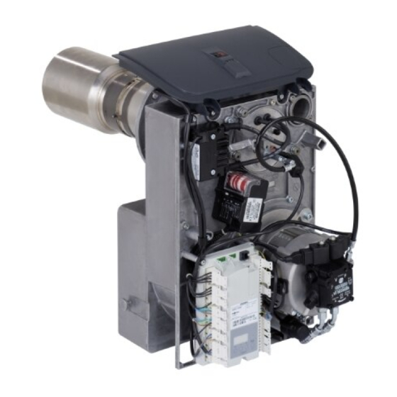
Page 22: Component Overview
Component overview Component overview Fig. 15 Service switch (for burner adjustment) Suction line or return line (differs subject to manu- Hood adaptor facturer) Quick-action fastener Solenoid valve, stage 2 Electronic ignition Solenoid valve, stage 1 Servomotor Flame monitor Burner control unit Return line or suction line (differs subject to manu- facturer) - Page 23 Component overview Component overview (cont.) Fig. 16 Reset button Blast tube connection Oil line Flame tube Oil pump Mixing device Fan motor Oil burner nozzle Fan casing Ignition electrodes Impeller Ignition cable Inlet air silencer Flange Air regulating valve Adaptor pipe...
-
Page 24: Connection And Wiring Dia
Connection and wiring diagram Connection and wiring diagram Fig. 17 Burner control unit (see chapter "Program Colour coding to DIN IEC 60757 sequence during commissioning") Black Fault indicator Black wire with imprint Reset button Brown Burner motor Blue Service switch (burner stage 2) Flame monitor GN/YE Green/yellow... -
Page 25: Report
Report Report Settings and test values Commissioning Maintenance/Service (Set values, see chapter "Standard values for burner adjustment", page 27) Oil pressure Stage 1 actual ■ Stage 2 actual ■ Vacuum actual after maintenance bar Soot value Stage 1 actual ■ after maintenance Stage 2 actual... -
Page 26: Specification
Specification Specification Rated boiler heating output = 50/30 67.6 85.8 107.3 º = 80/60 º Rated burner heat input 45.9/65.6 58.3/83.3 72.9/104.2 stage 1/2 Burner type VHG III-1 VHG III-2 VHG III-3 DIN registration no. Applied for Voltage Frequency Power consumption Stage 1: 585 Stage 2: 616 Motor speed... -
Page 27: Standard Values For Burner
Standard values for burner adjustment Standard values for burner adjustment Rated heating output of the boiler = 50/30 67.6 85.8 107.3 º = 80/60 º Oil burner nozzle Make: Danfoss Type º º º 1.35 1.75 Oil pressure approx. Stage 1 bar min. -
Page 28: Appendix Information On Fuel Oil
The use of combustion improvers that leave res- idues is not permitted. Biofuels Biofuels are made from vegetable oil, e.g. sunflower or rape seed oil. Please note Biofuels can lead to damage to Viessmann oil burners. Their use is not acceptable. -
Page 29: Keyword Index
Keyword index Keyword index Flame monitor, safety check........11 Additives for fuel oil............ 28 Flash code..............19 Air damper position............ 10 Flowchart, burner faults..........18 Air damper servomotor, checking settings....10 Fuel oil – Additives..............28 – Quality..............28 Biofuels..............28 Burner cleaning............12 Burner control unit Ignition air setting............ - Page 32 Viessmann Werke GmbH & Co. KG Viessmann Limited D-35107 Allendorf Hortonwood 30, Telford Telephone: +49 6452 70-0 Shropshire, TF1 7YP, GB Fax: +49 6452 70-2780 Telephone: +44 1952 675000 www.viessmann.com Fax: +44 1952 675040 E-mail: info-uk@viessmann.com...