
Related Manuals for Viessmann MatriX-Disk burner


Summary of Contents for Viessmann MatriX-Disk burner
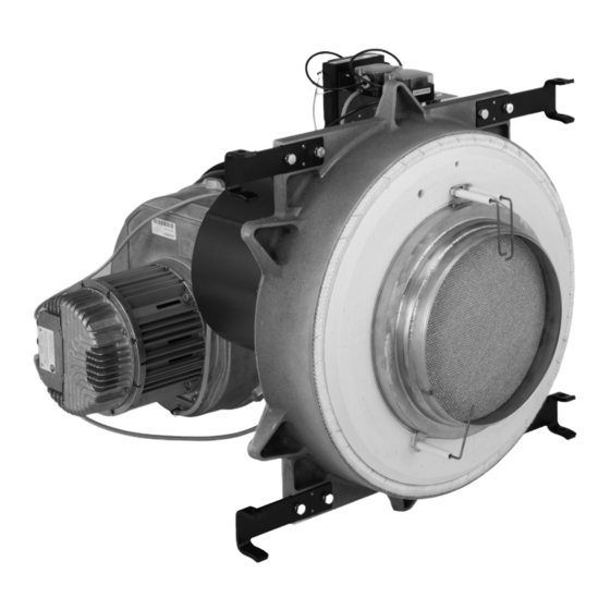
- Page 1 VIESMANN Service instructions for contractors MatriX-Disk burner Type MDI, 800 and 1000 kW MatriX-Disk burner for natural gas E and LL MatriX-Disk burner Please keep safe. 6151060 GB 1/2020...
- Page 2 Safety instructions Safety instructions Please follow these safety instruc- tions closely to prevent accidents and material losses. Safety instructions explained Danger Note This symbol warns against the risk Details identified by the word "Note" of injury. contain additional information. Please note This symbol warns against the risk of material losses and environmen- tal pollution.
- Page 3 Viessmann. water pipes to discharge static loads. Repair work Please note Repairing components that fulfil a safety function can compromise the safe operation of the system. Replace faulty components only with genuine Viessmann spare parts.
- Page 4 Safety instructions Safety instructions (cont.) Safety instructions for operating the system If you smell gas Condensate Danger Danger Escaping gas can lead to explo- Contact with condensate can be sions which may result in serious harmful to health. injury. Never let condensate touch your Do not smoke.
- Page 5 Safety instructions Safety instructions (cont.) Danger The simultaneous operation of the boiler and appliances that exhausts air to the outside can result in life threatening poisoning due to a reverse flow of flue gas. Fit an interlock circuit or take suita- ble steps to ensure an adequate supply of combustion air.
- Page 6 7. Connection diagrams Burner control unit connection diagram ..........47 8. Reports ........................ 48 9. Specification Specification – MatriX-Disk burner ............49 10. Final decommissioning Final decommissioning and disposal ............. 50 Certificates Declaration of conformity ............... 51 Manufacturer's certificate according to the 1st BImSchV [Germany] ..51 12.
- Page 7 Information Symbols The steps in connection with commissioning, inspec- Symbol Meaning tion and maintenance are found in the "Commission- Reference to other document containing ing, inspection and maintenance" section and identified further information as follows: Step in a diagram: Symbol Meaning The numbers correspond to the order in Steps required during commissioning...
- Page 8 Information Product information MatriX-Disk burner, type MDI Information about installation, commission- ■ Gas burner for Vitocrossal gas condensing boilers, ing, inspection and maintenance of the entire type CRU 800 and 1000 kW boiler ■ Modulation 1:6 ■ "Vitocrossal, type CRU" installation instruc- ■...
-
Page 9: Table Of Contents
Commissioning, inspection, maintenance Steps - commissioning, inspection and maintenance Commissioning steps Inspection steps Maintenance steps Page • • • 1. Information about commissioning, inspection and maintenance......... 10 • • • 2. Opening the boiler......................10 • • 3. Checking the electrical connections................10 •... -
Page 10: Information About Commissioning, Inspection And Maintenance
Commissioning, inspection, maintenance Information about commissioning, inspection and maintenance Steps that relate to the boiler are described in a sepa- Ensure the quality of the combustion air drawn in. rate manual. ■ Combustion air must be free from flammable, explo- sive gases and vapours. -
Page 11: Checking The Gas Control Cables
Commissioning, inspection, maintenance Checking the gas control cables Check control cables for ■ Connection and kink-free routing ■ Application and seating of retaining clips L=225 L=735 L=220 L=75 L=180 L=200 L=770 L=120 Fig. 2 Checking the gas type 1. Check with your gas supply utility regarding the 2. -
Page 12: Setting The Gas Type
Commissioning, inspection, maintenance Setting the gas type In the delivered condition, the boiler is preset for natu- ral gas E and can be changed over to natural gas LL. The setting can later be changed back to natural gas E. Fig. -
Page 13: Commissioning The Burner
Commissioning, inspection, maintenance Commissioning the burner Danger Vitotronic control unit operating instructions ■ CO build-up as a result of incorrect burner and service instructions adjustment or flue gas system leakage can have ■ Neutralising system operating instructions serious health implications. ■... -
Page 14: Reducing The Maximum Heating Output (If Required)
Commissioning, inspection, maintenance Reducing the maximum heating output (if required) The maximum heating output of the burner can be 4. S to confirm, "1" is shown under "Status". The cur- reduced if required. rent value for the maximum heating output in % is shown under "Service". -
Page 15: Checking The Static Pressure And Supply Pressure
Commissioning, inspection, maintenance Checking the static pressure and supply pressure Fig. 6 Test connector Static pressure 1. Close the gas shut-off valve. 5. Measure the static pressure: Max. 60 mbar (6 kPa). 2. Undo the screw in test connector . Do not remove the screw. -
Page 16: Measuring The Co Content
Commissioning, inspection, maintenance Checking the static pressure and supply pressure (cont.) 2. Measure the supply pressure (flow pressure) at 3. Record the actual value in the report. rated heating output. 4. Switch off the ON/OFF switch at the programming Natural gas E/LL unit of the Vitotronic control unit. - Page 17 Commissioning, inspection, maintenance Measuring the CO content (cont.) Adjusting screws on the gas train Fig. 8 Note 06. Check the CO content at the flue pipe. Check measurements and settings with a clean air fil- For permissible CO content, see the table. ter.
-
Page 18: Measuring The Co Content
Commissioning, inspection, maintenance Measuring the CO content (cont.) 08. Check the CO content at the upper and lower 09. Enter the actual values into the report. heating output again. 10. On the burner control unit, press S and simulta- If required, set the CO content for the upper and neously for longer than 2 s. -
Page 19: Checking The Fan Pressure And Aic Pressure
Commissioning, inspection, maintenance Checking the ionisation current (cont.) repeatedly until "0" is shown under "Service". 12. S to change to the operating display. Checking the fan pressure and AIC pressure 1. For the fan pressure, connect the pressure gauge to measuring point with a tee. -
Page 20: Shutting Down The System
Commissioning, inspection, maintenance Shutting down the system 1. Isolate the system from the power supply, e.g. by 2. Close the gas shut-off valve. removing the separate fuse or by means of a mains isolator, and check that it is no longer live. Safeguard the system against reconnection. -
Page 21: Opening The Combustion Chamber
Commissioning, inspection, maintenance Opening the combustion chamber 8. 3. 4. 6x Fig. 12 Danger Note Serious injuries can result from the burner door If the burner is operated in room sealed mode, remove falling shut. the room sealed set. Secure the burner door against unintentional closure. -
Page 22: Cleaning The Burner
Commissioning, inspection, maintenance Cleaning the burner Fig. 13 Fitting Air filter 4. Press and hold the blue ring on the push-fit con- 7. Clean fitting with integral swirl plate carefully nector to remove the compensation lines from the with compressed air. gas train and fan. -
Page 23: Checking The Burner Door
Commissioning, inspection, maintenance Cleaning the air filter (cont.) 2. Coarse dirt ■ Tap the air filter to remove larger pieces of dirt and dust. Please note Damage to the filter fleece impairs the function. Do not bang the filter against sharp edges. Light, dry dirt ■... -
Page 24: Checking And Cleaning The Burner Gauze Assembly
Commissioning, inspection, maintenance Checking and cleaning the burner gauze assembly 1. Check burner gauze assembly and thermal insulation block for damage and contamination. 2. If a component is visibly damaged, replace the component. Installation instructions "Replacing burner components" 3. In the event of contamination, clean the burner gauze assembly. -
Page 25: Fitting The Burner
Commissioning, inspection, maintenance Checking the ignition electrodes and ionisation… (cont.) 10° Fig. 19 Check the ignition electrodes and ionisation electrode Note for the correct gap to the burner gauze assembly and Do not bend the electrodes if the electrode gaps do not for possible damage. -
Page 26: Checking The Gas Train Valves For Tightness
Commissioning, inspection, maintenance Closing the combustion chamber (cont.) Tighten the burner door screws diagonally to a torque of 30 Nm. Danger Leaks in the burner door can result in poisoning through escaping flue gas. Check the burner door for flue gas tightness, e.g. -
Page 27: Checking The Gas Train Filter Element
Commissioning, inspection, maintenance Checking the gas train valves for tightness (cont.) 6. After completing the test, close the screw on test connector . Check the test connector for leaks. Danger Escaping gas leads to a risk of explosion. Check the test connector for gas tightness. Please note The use of leak detection spray can result in faulty operation. -
Page 28: Checking The Filter Element In The Gas Line
Commissioning, inspection, maintenance Checking the gas train filter element (cont.) 6. Check for gas tightness. Danger Escaping gas leads to a risk of explosion. Check the gas train for gas tightness. Please note The use of leak detection spray can result in faulty operation. -
Page 29: Checking The Installation Room Ventilation Air Apertures
Commissioning, inspection, maintenance Checking the installation room ventilation air apertures With open flue operation: Check that the ventilation opening in the installation room is open and sufficiently large. Instructing the system user The system installer should hand the operating instruc- This includes all components installed as accessories, tions to the system user and instruct the user in oper- e.g. - Page 30 Burner control unit Burner control unit VUC 310 Display and programming unit A display and programming unit is integrated into the Note burner control unit. Depending on the system configuration, some scans and settings can be carried out on the Vitotronic con- The following scans and settings are possible: trol unit of the boiler.
- Page 31 Burner control unit Burner control unit VUC 310 (cont.) Status Service Status Service Pre-purge Dwell program, no air pressure Status Service Status Service Dwell program, no gas Pre-ignition pressure or mains undervoltage Status Service Forced ventilation if no Status Service Ignition flame formation has been Safety time...
- Page 32 Burner control unit Burner control unit VUC 310 (cont.) Overview sub-menu to menu "1" Calling up all meter readings: — "Status" display "Service" display Start counter, 1 digit Start counter, 1000 digit Hours run meter, 1 digit Hours run meter, 1000 digit Overview sub-menu to menu "2"...
- Page 33 Burner control unit Burner control unit VUC 310 (cont.) "Status" display "Service" display: Process information Unit/scale Set speed PWM variable Actual speed n in 10/min Gas pressure switch 1 0 or 1 Gas pressure switch 2 0 or 1 Air pressure switch 1 0 or 1 Gas valve 1 0 or 1...
- Page 34 Burner control unit Burner control unit VUC 310 (cont.) 4. S to confirm; "1" is shown under "Status". The 6. S to confirm. If adopted successfully, "1" appears current value for the maximum operational out- under Service; if it failed, "0" will appear. put in % is shown under "Service".
- Page 35 Burner control unit Flow diagram for burner start Fig. 23...
- Page 36 Burner control unit Flow diagram for burner start (cont.) Description of state Phase "Service" Description Duration display System start "A" System start 10 s Fan ramp-up, system start max. 20 s Forced ventilation, system start 20 s Relay test "P" Fan ramp-up for test max.
- Page 37 Troubleshooting Fault display If the burner control unit recognises a fault, the fault 1. Remedy the fault. For fault codes and measures, display is automatically activated: see the following chapter. Carry out measures in ■ In the case of a non-lockout fault, the fault LED illu- the indicated order.
- Page 38 Troubleshooting Fault codes with display on burner control unit General process errors: Displayed fault codes Note Carry out measures in the order described. Each fault message is saved in the fault memory. The 10 most recent fault messages can be called up. Displayed fault System characteristics Cause...
- Page 39 Troubleshooting Fault codes with display on burner control unit (cont.) Displayed fault System characteristics Cause Measures code F E3 Burner control unit in a fault External safety equipment Check external safety equipment state has responded, e.g. mini- on STB/STB at plug of the aBÖ...
- Page 40 Troubleshooting Fault codes with display on burner control unit (cont.) Displayed fault System characteristics Cause Measures code F F4 No flame formation during Ionisation electrode incor- Insert plug of ionisation electrode; safety time; ionisation flame rectly adjusted; ionisation check cable; adjust ionisation elec- monitor reports no flame sig- electrode not plugged in.
- Page 41 Troubleshooting Fault codes with display on burner control unit (cont.) Displayed fault System characteristics Cause Measures code F F8 Flame tears off during modu- Air pressure switch 2 ad- Adjust air pressure switch 2 (see lation (burner output increa- justed incorrectly. page 45).
- Page 42 Troubleshooting Fault codes with display on burner control unit (cont.) Detailed error codes for F FD Detailed er- Component/signal Cause of fault Measure ror code Reset button Programming unit faulty Replace programming unit. Wiring Check wiring. Fuel valve 2 feed- Incorrect return voltage Remove plug from fuel valve 2, reset burner con- back...
- Page 43 Troubleshooting Faults without fault display (cont.) Fault Cause of fault Measure content too low Incorrect setting Check whether the burner has been adjusted to the correct gas type; change gas restrictor if required (see page 11 onwards). Adjust burner in accordance with the details on page 16 onwards.
- Page 44 Component overview Overview of burner components Fig. 25 Display and programming unit Thermal insulation block Burner control unit Ignition electrodes Burner door Burner gauze assembly, MatriX-Disk Gas train Ionisation electrode Gas pressure switch 1 Ignition unit Gas pressure switch 2 Air pressure switch LDW2 Gas supply pipe Air pressure switch LDW1...
- Page 45 Function description Air pressure switch Fan pressure monitoring function (LDW1) The switching threshold of air pressure switch 1 (plug The fault shutdown is indicated by fault codes "F F5" and "F F7" on the burner control unit display (see ) is monitored in all fan ramp-up phases and checked during modulating burner operation.
- Page 46 Function description Boiler water temperature sensors and flue gas… (cont.) NTC 10 k Ω Temperature in °C Fig. 26...
- Page 47 Connection diagrams Burner control unit connection diagram Fig. 27 Junction box Fuel valve BV2 Mains connection to main MCB/fuse 400 V/50 Hz, Display and programming unit see the following chapter Gas pressure switch GDW2 Burner control unit VUC 310 Air pressure switch 1 Flame monitor (ionisation current) Gas pressure switch GDW1 Vitotronic control unit...
- Page 48 Reports Reports Settings and measurement values Commissioning Maintenance/Service Static pressure mbar Supply pressure (flow pressure) Natural gas E mbar Natural gas LL mbar Tick gas type. Carbon dioxide content CO At the upper rated heat- Actual % by vol. ■ ing output % by vol.
- Page 49 Specification Specification – MatriX-Disk burner Vitocrossal, type CRU 800 CRU 1000 Rated heating output range 80/60 °C 125 to 750 156 to 938 50/30 °C 137 to 800 171 to 1000 cond Rated heating input range Qn (Sized for up to mean...
- Page 50 Final decommissioning Final decommissioning and disposal Viessmann products can be recycled. Components For decommissioning the system, isolate the system and substances from the system are not part of ordi- from the power supply and allow components to cool nary household waste.
- Page 51 Manufacturer's certificate according to the 1st BImSchV [Germany] We, Viessmann Werke GmbH & Co. KG, D-35107 Allendorf, confirm that the product MatriX-Disk burner, type MDI complies with the following conditions stipulated by the 1st German Immissions Order (BImSchV): ■...
- Page 52 Keyword index Keyword index Fault codes..............38 Air pressure switch.............45 Fault codes, detailed..........41 Fault display............... 37 Fault history..............37 Boiler, closing............. 28 Fault memory............. 37 Boiler, opening............10 Faults without fault display......... 42 Boiler water temperature sensors......45 Filter element checking, gas line........28 Burner Filter element checking, gas train......
- Page 53 Keyword index Keyword index (cont.) Specification...............49 Tightness Start and test functions during burner start..30, 35 – Gas connections............. 28 Static pressure, checking........... 15 – Gas train valves............26 Supply pressure, checking......... 15 Symbols............... 7 System Ventilation air apertures, checking......29 –...
- Page 56 Viessmann Werke GmbH & Co. KG Viessmann Limited D-35107 Allendorf Hortonwood 30, Telford Telephone: +49 6452 70-0 Shropshire, TF1 7YP, GB Fax: +49 6452 70-2780 Telephone: +44 1952 675000 www.viessmann.com Fax: +44 1952 675040 E-mail: info-uk@viessmann.com...