Viessmann VITOFLAME 200 Service Instructions Manual
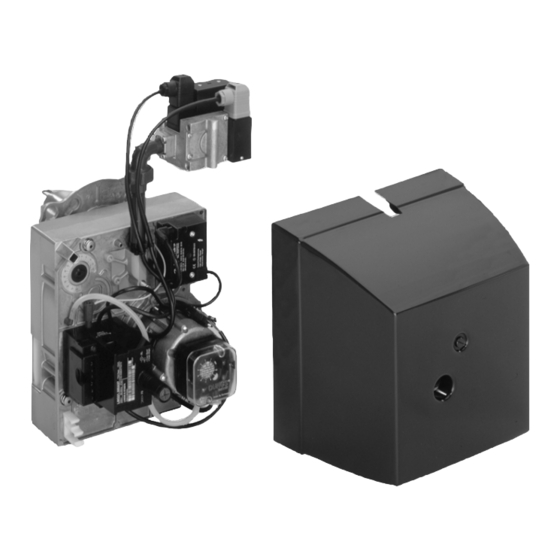
Gas pressure jet burner (type vga) for vitola and vitorond 200 rated output 15 to 63 kw
Hide thumbs
Also See for VITOFLAME 200:
- Service instructions manual (44 pages) ,
- Service instructions manual (44 pages)
Table of Contents

Related Manuals for Viessmann VITOFLAME 200


Summary of Contents for Viessmann VITOFLAME 200
- Page 1 Service instructions for heating engineers Vitoflame 200 Gas pressure jet burner (type VGA) for Vitola and Vitorond 200 rated output 15 to 63 kW See notes on applicability, page 2. VITOFLAME 200 5692 449 GB 1/2002 File in: Service folder...
-
Page 2: General Information
Use only original Viessmann spare ¨ Caution safeguard against unauthorised parts or equivalent, which have been re−connection. -
Page 3: Table Of Contents
Contents Page General Information Safety instructions ................... . Applicability . - Page 4 Initial start−up, inspection and maintenance Procedure summary Initial start−up steps Steps for twice annual inspection Maintenance steps 1. Initial start−up Page 5 ..........................2.
-
Page 5: Initial Start−Up
Initial start−up, inspection and maintenance Implementation To obtain optimum combustion values, it is essential that the burner is adjusted with the boiler heated to operating temperature. Check the CO content, CO content, flue gas temperature, room temperature and chimney draught after 2 minutes operation and at 60 ºC boiler water temperature with fitted burner hood. -
Page 6: Setting The Rated Output
Initial start−up, inspection and maintenance Implementation (cont.) 2. Setting the rated output nitial start−up aint. Check the type of gas with your local gas supplier. The burner is factory−set to natural gas E. Adjust the nozzle pressure for operation with natural gas LL according to table 22. -
Page 7: Initial Start−Up
Initial start−up, inspection and maintenance Implementation (cont.) 2. Setting the rated output (cont.) nitial start−up aint. Supply pressure 7. Start up the burner. Initial start−up, see page 5. 8. Check the supply pressure (flow The supply pressure (flow pressure), see the table below. pressure) should be between 20 and 25 mbar. - Page 8 Initial start−up, inspection and maintenance Implementation (cont.) 2. Setting the rated output (cont.) nitial start−up aint. Nozzle pressure 13. Loosen the screw in the test nipple B but do not remove, and connect the U−shaped pressure gauge. 14. Open the gas shut−off valve and start the burner.
-
Page 9: Safety Instructions
Initial start−up, inspection and maintenance Implementation (cont.) 2. Setting the rated output (cont.) nitial start−up aint. Start gas volume The opening characteristics of the gas solenoid valve have been matched to the boiler and have been preset at the factory. Generally, you do not need to change this setting. -
Page 10: M 4. Checking The Burner
Initial start−up, inspection and maintenance Implementation (cont.) 4. Fully check the burner aint. Safety instructions Record the actual values in their true sequence in the service report on the Measure the CO value before and last pages of this manual. after any work on gas appliances, to prevent any health hazards and to ensure perfect system conditions. -
Page 11: Cleaning The Burner
Initial start−up, inspection and maintenance Implementation (cont.) 8. Cleaning the burner nspection aint. 1. Set the burner to maintenance. 2. Clean the housing C, the flame Cleaning the combustion tube A, the mixer B together chamber and hot gas flues, with the ignition and ionisation see boiler service electrode and the impeller D. -
Page 12: I M 11. Cleaning The Sensor Plate (If Necessary)
Initial start−up, inspection and maintenance Implementation (cont.) 11. Cleaning the gas outlet holes in the sensor plate (if necessary) nspection aint. 1. Remove the cables from the electrodes H and 2. Loosen the electrode holders K and A, and remove the ignition and ionisation electrodes. -
Page 13: Checking Both Gas Train Valves
1 mbar, the gas train is tight ³ continue with step 6). Otherwise the system leaks − in that case return the gas train to Viessmann Werke for tests. 6. After the test, close both test nipples by inserting screws. Gas train (make: Kromschröder) -
Page 14: I M 15. Checking The Gas Train Filter Insert (Manufacturer: Dungs)
Initial start−up, inspection and maintenance Implementation (cont.) 15. Checking the gas train filter insert (make Dungs), nspection aint. and replacing, if necessary. 1. Close the gas shut−off valve. 2. Unscrew the filter lid D. 3. Withdraw the filter element B. 4. -
Page 15: I I M
Initial start−up, inspection and maintenance Implementation (cont.) 18. Checking the ionisation current nitial start−up nspection aint. 1. Switch off the mains electrical isolator. Please note: 2. Separate the plug connection of the ionisation current cable (red For checking with Testomatik Gas, cable). - Page 16 Troubleshooting Procedure summary Diagnosis 1. Establish fault/ascertain the system characteristics. 2. Check for the corresponding cause of the fault in the diagnostic tables. 3. Establish the action required from the table. Remedy 4. Correct the fault.
-
Page 17: Diagnosis
Troubleshooting Diagnosis Function sequence (see page 27): Start command Ignition time Switching on by thermostat. Ramp up during the safety Delay: approx. 3 s time (TSA). TSA Safety time: max. 5 or 3 s Air pressure switch and flame relay are checked for correct At the end of TSA (ramp−up contact position. - Page 18 Troubleshooting Diagnosis (cont.) Fault/system characteristics Flashing Cause of fault Check code red No voltage. Check the fuse in the control unit, Burner does not start, check the electrical connections, the demand lamp does not illuminate. position of the ON/OFF switch on the control unit and the mains electrical isolator.
- Page 19 Troubleshooting Diagnosis (cont.) Fault/system characteristics Flashing Cause of fault Check code red 2 × flashes Insufficient combustible Vent gas supply line to the outside. Burner starts up, but no gas mixture available. Check with a test burner, if sufficient flame is formed. combustible gas is available.
- Page 20 Troubleshooting Diagnosis (cont.) Check Fault/system characteristics Flashing Cause of fault code red Incorrect setting. Adjust the nozzle pressure in content too low or O accordance with the type of gas content too high. used. Correct the air damper setting. Infiltrating air. Seal the flue pipe at the boiler adaptor.
-
Page 21: Specification
Additional information Specification Rated output Rated thermal load 16.5 19.8 24.2 29.7 36.2 43.9 54.9 69.2 Type of burner VGAI 1 VGAI 1 VGAI 1 VGAI 1 VGAI 2 VGAII 1 VGAII 2 VGAII 2 Product ID CE 0085 BM 0436 Voltage Frequency Power... -
Page 22: Standard Values For Burner Settings
Additional information Standard values for burner settings Check whether the service instructions are valid for the boiler concerned (see notes on applicability, page 2 and serial no. on the burner type plate). Nozzle pressure table Gas family Gas Wobbe index Supply pp y Rated boiler output... -
Page 23: Ignition And Ionisation Electrode
Additional information Standard values for burner settings (cont.) Ignition and ionisation electrode 15 to 40 kW A Ionisation electrode D The tip of the ignition electrode E The gas outlet holes in the end B Ignition electrode is directed to the edge of the plate are directed towards the C Earth electrode air guide slots... -
Page 24: Standard Values For Sensor Plate, Restrictor And Blast Tube
Additional information Standard values for sensor plate, restrictor and blast tube Output Sensor plate Sensor plate no. Dimension a mm 67.8 67.8 67.8 67.8 67.8 67.8 80.1 80.1 Restrictor in the gas supply pipe Dimension b mm 8.7 Without restrictor Blast tube Dimension c mm... -
Page 25: Component Summary
Additional information Component summary A Gas throughput valve with G Ionisation cable R Ionisation electrode H Gas burner control unit S Earth electrode integrated safety shut−off valve B Gas train I Reset button T Sensor plate C Restrictor (inside the fitting) K Connection panel U Ignition electrode D Gas connection... -
Page 26: Wiring Diagram
(e.g. KNL, extension lead, etc.) Connection of external safety equipment via system plug−in connector aBÖ Connection of external control off−switch via system plug−in connector aBÖ Connection for external burner ON Please note: This wiring diagram only applies in conjunction with Viessmann products. 27/28... - Page 27 Additional information Parts list When ordering spare parts: Quote the type and serial no. (see type plate) and the item no. of the required part (as per parts list). You can obtain common parts from your local supplier. Parts 001 Burner housing with air damper 002 Blast tube 003 Small parts comprising: see below...
- Page 28 Additional information Parts list (cont.) Parts 003 Small parts comprising: see below 013 Mixer head 016 Impeller 020 Sensor plate 021 Earth cable 022 Electrode holder 023 Connection interference suppression ignition cable 003 Small parts comprising: 3a Plug spigot hexagon socket 4 mm 3b Plug spigot compression spring 3c Plug spigot lockwasher...
- Page 29 Additional information Parts list (cont.) Gas train (make: Kromschröder), type CG 10 Gas train (make: Dungs), type MB DLE 405 B 01 Parts 003 Small parts comprising: see below 031 Set of sealing washers 034 Gas train (make: Kromschröder), type CG 10 035 Gas train (make: Dungs), type MB DLE 405 B 01 036 Stop cock ½"...
- Page 31 Additional information Certificate of conformity for gas burners We, Viessmann Werke GmbH & Co D 35107 Allendorf, declare as sole responsible body, that the product Vito flame 200, type VGA conforms to the following standards: This product is identified in...
- Page 32 Additional information Commissioning/service report...
- Page 33 Additional information Commissioning/service report (cont.)
-
Page 34: Index
22 Gas train filter element, checking and replacement, 14 Gas train valves, checking for leaks, 13 Viessmann Werke GmbH & Co D 35107 Allendorf Tel: (0 64 52) 70 0 Fax: (0 64 52) 70 27 80 www.viessmann.de...