Viessmann Vitoflame 100 Service Instructions Manual
Oil pressure jet burner (type ve iii) for vitoplex 100 rated output 90 to 210 kw
Hide thumbs
Also See for Vitoflame 100:
- Service instructions manual (68 pages) ,
- Service instructions for contractors (56 pages) ,
- Service instructions manual (44 pages)
Table of Contents
Advertisement
Quick Links
Advertisement
Table of Contents

Related Manuals for Viessmann Vitoflame 100


Summary of Contents for Viessmann Vitoflame 100
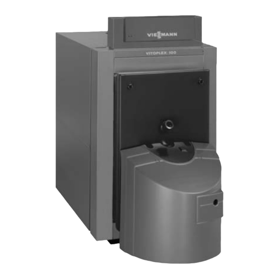
- Page 1 Vitoflame 100 Oil pressure jet burner (type VE III) for Vitoplex 100 Rated output 90 to 210 kW See notes on applicability, page 2. VITOFLAME 100 Vitoflame 100 oil burner fitted to Vitoplex 100 Please keep safe 5692 533 GB 5/2003...
-
Page 2: General Information
Repair work It is not permitted to carry out repairs on parts that fulfil a safety function. Use only original Viessmann spare parts, or equivalent parts that have been approved by Viessmann. Applicability from serial no. -
Page 3: Table Of Contents
Contents Index Page General information Safety instructions ........................Applicability . -
Page 4: Initial Start-Up, Inspection And Maintenance
Initial start-up, inspection and maintenance Steps initial start-up, inspection and maintenance For further instructions on individual steps, see pages indicated. Commissioning steps Inspection steps Maintenance steps Page 1. System start-up ................2. -
Page 5: Further Details Regarding The Individual Steps
Initial start-up, inspection and maintenance Further details regarding the individual steps To obtain the optimum combustion values, it is essential to adjust the burner with the boiler heated to operating temperature (min. 60 ºC). Also carry out measurements at base load. System start-up Service instructions Boiler control unit... -
Page 6: Checking Adjustment Of Air Damper Actuator
Initial start-up, inspection and maintenance Further details regarding the individual steps (cont.) Checking adjustment of air damper actuator The burner is equipped with an air damper actuator motor with adjustable switching cams for setting the air damper position and for switching the solenoid valves. -
Page 7: Oil Pressure Adjustment And Vacuum Check
Initial start-up, inspection and maintenance Further details regarding the individual steps (cont.) Oil pressure adjustment and vacuum check The oil pressure is preset at the factory according to the oil throughput. Re-adjust the oil pressure if necessary. 1. Isolate the mains electrical isolator and safeguard against unauthorised reconnection. - Page 8 Initial start-up, inspection and maintenance Further details regarding the individual steps (cont.) 7. If necessary, adjust the oil pressure at the pressure adjusting screw for stage 1 C and stage 2 D. Turn clockwise ³ pressure rises Anti-clockwise ³ pressure falls. For standard values for burner settings, see page 37.
-
Page 9: Air Volume Adjustment
Initial start-up, inspection and maintenance Further details regarding the individual steps (cont.) Air volume adjustment The air volume is preset at the factory. If necessary, readjust the air volume, first adjusting the air volume for stage 2 at the blast tube connection. Starting up the burner may require a fine adjustment. - Page 10 Initial start-up, inspection and maintenance Further details regarding the individual steps (cont.) Fine adjustment stage 1 1. Set service switch E to position II (automatic mode), and close the cover flap. 2. Switch the burner over to stage 1 by pulling plug lÖ. 3.
-
Page 11: Checking And Cleaning Flame Monitor
Initial start-up, inspection and maintenance Further details regarding the individual steps (cont.) Checking and cleaning flame monitor Remove flame monitor A (photo resistance) from its holder with the burner running. The system should then perform a fault shutdown, if the flame monitor is covered up. -
Page 12: Cleaning Burner
Initial start-up, inspection and maintenance Further details regarding the individual steps (cont.) Cleaning burner 1. Set the burner to maintenance. For cleaning the combustion chamber and hot gas flues, 2. Clean the housing, the flame tube, see boiler service sensor plate A, ignition instructions. -
Page 13: Nozzle Replacement
Initial start-up, inspection and maintenance Further details regarding the individual steps (cont.) Nozzle replacement 1. Remove sensor plate A from the blast tube connection. 2. Replace nozzle B (hold the blast tube connection to avoid the formation of air bubbles inside the blast tube connection). -
Page 14: Checking And, If Required, Adjusting Ignition Electrodes
Initial start-up, inspection and maintenance Further details regarding the individual steps (cont.) Checking and, if required, adjusting ignition electrodes Check ignition electrodes A for wear, contamination and size (see fig.) and replace if necessary. - Page 15 Initial start-up, inspection and maintenance Further details regarding the individual steps (cont.) Oil pump filter, cleaning and replacing if necessary, Danfoss oil pump, type BFP 52 A Filter plug B O ring (replace) C Filter (replace) Suntec oil pump, type AT 2 55 A Filter (clean or replace)
-
Page 16: Diagnostics
Troubleshooting Diagnostics Fault Cause Remedy Burner does not start No voltage present Check fuse in control unit and in plug-in terminal block, check electrical connections, position of ON/OFF switch on control unit and mains electrical isolator High limit safety cut-out Press reset button on activated boiler control unit... - Page 17 Troubleshooting Diagnostics (cont.) Fault Cause Remedy Pump does not feed oil Shut-off valves closed at Open valves filter or in oil pipe Filter blocked Clean filter (pre-filter and pump filter) Clutch between motor Replace clutch and pump faulty Suction pipe leaking Tighten connections.
- Page 18 Troubleshooting Diagnostics (cont.) Fault Cause Remedy Flame extinguishes Air in suction line Seal line and filter during operation Nozzle faulty Nozzle replacement Air incorrectly adjusted, Adjust pre-settings pump pressure correctly (see page 37) incorrectly adjusted Sensor plate and inside Clean sensor plate and of flame tube inside of flame tube contaminated...
- Page 19 Troubleshooting...
-
Page 20: Component Summary
Component summary Component summary A Service switch S Flame monitor (for burner adjustment) T Mounting plate for B Hood adaptor burner hood adaptor C Quick-action fastener U Valve housing D Ignition transformer V Suction air silencer E Burner control unit W Impeller F Reset button X Air regulating damper... - Page 21 Component summary Component summary (cont.)
- Page 22 Component summary...
-
Page 23: Connection And Wiring Diagrams
90 D Internal connection inside black plug-in connector lÖ black wire with imprint brown 1 qW Plug-in terminals on burner blue control unit GNYE green/yellow Please note: The wiring diagrams on the following pages only apply in conjunction with Viessmann products. - Page 24 Connection and wiring diagrams Connection and wiring diagram (cont.) Flame monitoring through photo resistance Terminals 3 and 8 are shown twice for clarity only Control (slow) unit components Control unit components Actuator Actuator Control Burner Solenoid Hours run burner stage 2 motor valve counter...
- Page 25 Connection and wiring diagrams Connection and wiring diagram (cont.) Burner control unit Solenoid Hours run Hours run Solenoid Ignition Flame External valve counter counter valve at trans- monitor fault stage 1 stage 1 stage 1 oil pump former message external if using an oil meter Ignition...
- Page 26 Connection and wiring diagrams Connection and wiring diagram (cont.) Flame monitoring through flicker light detector Terminals 3 and 8 are shown twice for clarity only Control (slow) unit components (slow) Control unit components Actuator Actuator Control Burner Solenoid Hours run burner stage 2 motor valve...
- Page 27 Connection and wiring diagrams Connection and wiring diagram (cont.) Burner control unit Solenoid Hours run Hours run Solenoid Ignition Flame External valve counter counter valve at trans- monitor fault stage 1 stage 1 stage 1 oil pump former message external if using an oil meter Solenoid valve...
-
Page 28: Parts List
Parts list Parts list When ordering spare parts 065 Solenoid valve nut for Suntec oil Quote the type and serial no. (see pump 081 Strapping plug no. 121 type plate) and the item no. of the required part (as per parts list). 082 Fuse 4 A/250 V (slow) Obtain common parts from your 083 Strapping plug no. - Page 29 Parts list Parts list (cont.) 003 Small parts comprising: Wear parts 3a Cheese-head screw M 6 × 16 029 Ignition electrode 3b Cheese-head screw M 6 × 10 031 Nozzle 3c Serrated washer A 6.4 061 Spare parts kit for Suntec oil 3d Double clip 18 ×...
- Page 30 Parts list Parts list (cont.)
- Page 31 Parts list Parts list (cont.)
- Page 32 Parts list Parts list (cont.)
- Page 33 Parts list Parts list (cont.)
- Page 34 Parts list Parts list (cont.) Danfoss oil pump, type BFP 52E L3...
- Page 35 Parts list Parts list (cont.) Suntec oil pump, type AT2-55C 9572...
-
Page 36: Appendix
Appendix Specification Rated output from kW range to kW Boiler output Burner output 106/ 114/ 125/ 145/ 160/ stage 1/2 Type of burner VE III 1PX VE III 2PX VE III 3PX VE III 4PX Type test no. acc. to EN 267 Voltage Frequency Power... -
Page 37: Standard Values For Burner Settings
Appendix Standard values for burner settings Please note: Check that the service instructions are valid for the burner concerned (see notes on applicability, page 2 and serial no. on the burner type plate). Rated output from kW range to kW Boiler output Oil burner nozzle Make Fluidics... -
Page 38: Commissioning/Service Report
Appendix Commissioning/service report Setting and test values Initial start-up Date: Oil pressure Stage 1 actual Stage 2 actual Vacuum actual after maintenance bar Soot indicator Stage 1 located after maintenance Stage 2 located after maintenance Carbon dioxide content CO Stage 1 actual % by vol. - Page 39 Appendix Maint./service Maint./service Maint./service Maint./service...
- Page 40 Appendix Commissioning/service report (cont.) Setting and test values Initial start-up Date: Flue gas loss Stage 1 actual Stage 2 actual actual Draught (at boiler end) adjusted Blast connection setting actual Air damper adjustment located Switch cam position at ST 1 actual º...
- Page 41 Appendix Maint./service Maint./service Maint./service Maint./service...
- Page 42 Appendix Commissioning/service report (cont.) Setting and test values Maint./service Date: Oil pressure Stage 1 actual Stage 2 actual Vacuum actual after maintenance bar Soot indicator Stage 1 located after maintenance Stage 2 located after maintenance Carbon dioxide content CO Stage 1 actual % by vol.
- Page 43 Appendix Maint./service Maint./service Maint./service Maint./service...
- Page 44 Appendix Commissioning/service report (cont.) Setting and test values Maint./service Date: Flue gas loss Stage 1 actual Stage 2 actual actual Draught (at boiler end) adjusted Blast connection setting actual Air damper adjustment located Switch cam position at ST 1 actual º...
- Page 45 Appendix Maint./service Maint./service Maint./service Maint./service...
- Page 46 Appendix Commissioning/service report (cont.) Setting and test values Maint./service Date: Oil pressure Stage 1 actual Stage 2 actual Vacuum actual after maintenance bar Soot indicator Stage 1 located after maintenance Stage 2 located after maintenance Carbon dioxide content CO Stage 1 actual % by vol.
- Page 47 Appendix Maint./service Maint./service Maint./service Maint./service...
- Page 48 Appendix Commissioning/service report (cont.) Setting and test values Maint./service Date: Flue gas loss Stage 1 actual Stage 2 actual actual Draught (at boiler end) adjusted Blast connection setting actual Air damper adjustment located Switch cam position at ST 1 actual º...
- Page 49 Appendix Maint./service Maint./service Maint./service Maint./service...
- Page 50 Appendix...
- Page 51 Appendix...
-
Page 52: Keyword Index
Ignition electrodes setting, 14 Nozzle replacement, 13 Oil pressure adjustment, 7 Oil pump filter, cleaning and replacing if necessary, 15 Operating and service Viessmann Werke GmbH & Co documents, 2 D 35107 Allendorf Tel: +49 6452 70 0 Fax: +49 6452 70 27 80 www.viessmann.de...