
Related Manuals for Viessmann VITOFLAME 300


Summary of Contents for Viessmann VITOFLAME 300
- Page 1 VIESMANN Service instructions for contractors Vitoflame 300 Type VHG, 18 to 33 kW Pressure-jet oil burner ■ With oil preheating ■ For Vitoladens 300-T and Vitorondens 200-T/222-F VITOFLAME 300 Please keep safe. 5777267 GB 8/2019...
- Page 2 Safety instructions Safety instructions Please follow these safety instruc- tions closely to prevent accidents and material losses. Safety instructions explained Danger Note This symbol warns against the risk Details identified by the word "Note" of injury. contain additional information. Please note This symbol warns against the risk of material losses and environmen- tal pollution.
- Page 3 For replacements, use only original safe operation of the system. spare parts supplied or approved by Replace faulty components only Viessmann. with genuine Viessmann spare parts. Safety instructions for operating the system If you smell flue gas Flue systems and combustion air...
- Page 4 Safety instructions Safety instructions (cont.) Extractors Danger The simultaneous operation of the Operating appliances that extract air to boiler and appliances that extract the outside (extractor hoods, extractors, air to the outside can result in life air conditioning units, etc.) can create threatening poisoning due to a negative pressure.
-
Page 5: Table Of Contents
Index Index 1. Information Symbols ....................Spare parts lists ..................2. Commissioning, inspec- Steps - commissioning, inspection and maintenance ......tion, maintenance 3. Burner control unit Burner control unit LMO 64.301 ............. 14 Program sequence during commissioning ......... 14 ■ Function and fault indication by indicator light (LED) ...... - Page 6 In conjunction with a tool: Clean the sur- ■ face. Dispose of component correctly. Dispose of component at a suitable collec- tion point. Do not dispose of component in domestic waste. Spare parts lists Information about spare parts can be found on the Viessmann spare parts app.
- Page 7 Commissioning, inspection, maintenance Steps - commissioning, inspection and maintenance Commissioning steps Inspection steps Maintenance steps Page • 1. Commissioning the system....................• • 2. Adjusting the air volume....................• • 3. Adjusting the oil pressure and checking the vacuum............ • •...
-
Page 8: Commissioning The System
Boiler control unit service instructions 4. Switch ON the mains isolator (outside the installa- tion room). Note The Vitoflame 300 pressure-jet oil burner features very 5. Switch ON the system ON/OFF switch at the con- good combustion values which are achieved without trol unit. - Page 9 Commissioning, inspection, maintenance Adjusting the oil pressure and checking the… (cont.) 01. Switch off at mains isolator and safeguard against reconnection. 02. Unscrew plug "P" from the oil pump. 03. Unscrew plug "V" from the oil pump. Note Place a suitable container below, to catch any oil that may leak out.
-
Page 10: Testing The Burner And Entering The Actual Values Into The Report
Commissioning, inspection, maintenance Adjusting the oil pressure and checking the… (cont.) 11. Check the plug seal rings for damage and replace if necessary. Insert plugs "P" and "V" 12. Start the burner and check the plugs for leaks. Testing the burner and entering the actual values into the report Note In the case of room sealed operation, observe the information regarding burner adjustments in the chap-... -
Page 11: Checking The Impeller Fixings
Commissioning, inspection, maintenance Checking the impeller fixings Checking the flame tube fixings Replacing the nozzle 1. Place the burner cover with the blast tube connec- tion facing upward on the burner casing (service position). This prevents the formation of bubbles in the blast tube connection. -
Page 12: Fitting The Burner Cover On The Burner Casing
Commissioning, inspection, maintenance Checking and adjusting the mixing assembly (cont.) Fig. 8 Rated heating output VHG I-2 VHG I-3 VHG I-4 VHG I-5 Designation Dimension a Fitting the burner cover on the burner casing Cleaning the oil pump filter and replacing it if required Fig. -
Page 13: Replacing The Filter Element Of The Fuel Oil Filter
Commissioning, inspection, maintenance Cleaning the oil pump filter and replacing it… (cont.) Fig. 10 Suntec oil pump, type ALE 35 Filter (clean or replace) O-rings (replace) Flat gasket (replace) Cover Replacing the filter element of the fuel oil filter Commissioning the system Checking the oil lines and connections for leaks Re-testing the burner and entering the actual values into the report... -
Page 14: Burner Control Unit Lmo 64.301
Pre-ignition time approx. 15 s flashing (see chapter "Faults with flash code indica- Pre-flushing time approx. 15 s tion"), contact your local Viessmann sales office. Safety time max. 10 s Controlled intermittent operation Post-ignition time when flame approx. 3 s... -
Page 15: Function And Fault Indication By Indicator Light (Led)
Burner control unit Burner control unit LMO 64.301 (cont.) Cause Response After a power failure Restart After falling below the undervoltage level Restart If there is a premature, faulty flame signal during pre- Fault shutdown at the end of pre-flush time c flush time c If there is a premature, faulty flame signal during oil Starting is prevented, fault shutdown after max. - Page 16 Burner control unit Burner control unit LMO 64.301 (cont.) 1. Press reset button for approx. 5 s ( 3 s) until > the signal lamp illuminates yellow. 2. A flash code is then shown as fault indication. Meaning of the flash code: See the table in chapter "Faults with flash code indication".
-
Page 17: Burner Fault Flowchart
Burner control unit Burner control unit LMO 64.301 (cont.) Burner fault flowchart System cold LED on burner control unit il- luminates red Reset burner control unit: Call up flash code: Call up data transfer for in- Press reset button for approx. Press the reset button for ap- terface (accessories): 1 s (<... -
Page 18: Diagnosis
Troubleshooting Diagnosis Fault indication with flash code Fault Red flash Cause of fault Measure code Burner does not start (with 10 x Electrical connection faulty, wires Check the electrical connection. fault indication), indicator "L 1" and "N" interchanged or If phases are correctly connec- light illuminates. -
Page 19: Faults Without Flash Code Indication
Troubleshooting Diagnosis (cont.) Fault Red flash Cause of fault Measure code Fan motor faulty Fan motor occasionally does not Replace the motor or capacitor. start, due to faulty auxiliary wind- ing or capacitor. Burner starts, but no oil is Solenoid valve coil is faulty. Replace solenoid valve coil. - Page 20 Troubleshooting Diagnosis (cont.) Fault Cause of fault Measure Flame pulsates, tears off. Fan pressure too high Check the static burner pressure at the test connector on top of the fan casing (U-tube pressure gauge). Adjust the air damper and blast tube connection so that the lower static burner pressure (see chapter "Standard values for burner ad- justment") is not exceeded.
- Page 21 Troubleshooting Diagnosis (cont.) Fault Cause of fault Measure Excessive flue gas temper- Excessive oil throughput Match oil throughput to rated boiler heat- ature ing output. Boiler and flue gas heat exchanger dirty Clean boiler and flue gas heat exchanger; correct burner settings. Air in flue gas heat exchanger Vent flue gas heat exchanger.
-
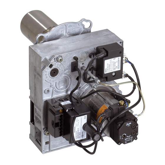
Page 22: Component Overview
Component overview Component overview Fig. 13 Air regulating valve Fan motor Burner control unit Oil pump Reset button with extension Solenoid valve Connection panel Oil line Return line HF ignition unit Suction line (with flame monitoring) - Page 23 Component overview Component overview (cont.) Fig. 14 Return line Ignition electrodes Suction line Flame tube Fan motor Mixing device Oil pump Oil burner nozzle Solenoid valve Blast tube connection with oil preheater Oil line Air routing HF ignition unit Air intake (with flame monitoring) Impeller Ignition cable...
- Page 24 Fig. 15 Note Oil preheater This wiring diagram only applies in conjunction with Burner motor Viessmann products. Solenoid valve for external connection via sepa- rate adaptor Burner plug at the control unit HF ignition unit with flame monitor Fuse in the control unit...
-
Page 25: Standard Values For Burner Adjustment
Standard values for burner adjustment Standard values for burner adjustment Notes regarding burner settings for room sealed operation The burner must be adjusted with all associated pipes Once it has been adjusted, no further pipes may be adapted and connected (e.g. ventilation air, flue gas). connected and existing pipes may not be removed or altered. - Page 26 Standard values for burner adjustment Standard values for burner adjustment (cont.) Example: Geodetic height 600 m above sea level Outside temperature 5 °C Air pressure 925 mbar Result: Adjust CO content to 13.6 %. Rated heating output Oil burner nozzle Make: Danfoss Type 80°...
-
Page 27: Report
Commissioning/service reports Report Settings and test values Commissioning Maintenance/service Oil pressure actual Vacuum actual after maintenance Soot value actual after maintenance Carbon dioxide content actual % by vol. % by vol. Carbon monoxide con- actual tent CO Oxygen content O actual % by vol. - Page 28 Specification Specification Rated boiler heating output Burner type VHG I-2 VHG I-3 VHG I-4 VHG I-5 DIN reg. no. to EN 267 5G999/S Voltage Frequency Power consumption includes 4 ignition processes per hour Motor speed 2800 Version Single stage Oil pump rate Connections ⅜...
-
Page 29: Final Decommissioning And Disposal
Final decommissioning Final decommissioning and disposal Viessmann products can be recycled. Components and substances from the system are not part of ordi- nary household waste. For decommissioning the system, isolate the system from the power supply and allow components to cool down where appropriate. - Page 30 Keyword index Keyword index Adjusting the air volume..........8 Inlet air aperture, setting..........8 Adjusting the oil pressure and checking the vacuum... 8 Inlet air aperture position..........26 Air damper setting............26 LE nozzle shut-off function........... 9 Burner LE setting screw............9 – Adjusting..............25 –...
- Page 32 Viessmann Werke GmbH & Co. KG Viessmann Limited D-35107 Allendorf Hortonwood 30, Telford Telephone: +49 6452 70-0 Shropshire, TF1 7YP, GB Fax: +49 6452 70-2780 Telephone: +44 1952 675000 www.viessmann.com Fax: +44 1952 675040 E-mail: info-uk@viessmann.com...