Viessmann Vitopend 100-W Installation And Service Instructions For Contractors
Gas system and combi boilers for open flue operation natural gas and lpg version
Hide thumbs
Also See for Vitopend 100-W:
- Installation and service instructions manual (136 pages) ,
- Operating instructions manual (48 pages) ,
- Installation and service instructions manual (60 pages)
Table of Contents
Advertisement
Advertisement
Table of Contents

Related Manuals for Viessmann Vitopend 100-W


Summary of Contents for Viessmann Vitopend 100-W
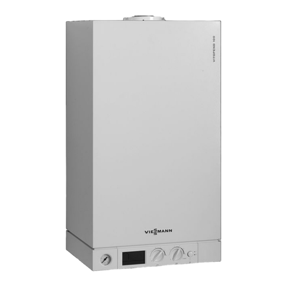
- Page 1 VIESMANN Installation and service instructions for contractors Vitopend 100-W Type WH1D, 10.5 to 24 kW and 13.5 to 30 kW Gas system and combi boilers For open flue operation Natural gas and LPG version For applicability, see the last page VITOPEND 100-W Please keep safe.
- Page 2 Safety instructions Safety instructions Please follow these safety instructions closely to prevent accidents and mate- rial losses. Safety instructions explained ■ The Code of Practice of relevant trade associations Danger ■ All current safety regulations as This symbol warns against the defined by DIN, EN, DVGW, TRGI, risk of injury.
- Page 3 Safety instructions Safety instructions (cont.) If you smell flue gas Danger The simultaneous operation of Danger the boiler and appliances that Flue gas can lead to life threat- extract air to the outside can ening poisoning. result in life threatening poison- ■...
- Page 4 Please note Repairing components that fulfil a safety function can compromise the safe operation of the sys- tem. Faulty components must be replaced with original Viessmann spare parts. Auxiliary components, spare and wearing parts Please note Spare and wearing parts that...
- Page 5 Index Index Installation instructions Preparing for installation................... Installation sequence Mounting the boiler and making connections............Flue gas connection..................... 11 Gas connection....................12 Opening the control unit enclosure............... 13 Electrical connections................... 14 Service instructions Commissioning, inspection, maintenance Steps - commissioning, inspection and maintenance.......... 17 Further details regarding the individual steps............
- Page 6 Index Index (cont.) Specification....................... 66 Certificates Declaration of Conformity for the Vitopend 100-W..........68 Keyword index....................69...
- Page 7 Preparing for installation Vitopend 100-W, type WH1D Set up for operation with natural gas E. The Vitopend 100-W must only be deliv- May be converted to alternative gas ered to the countries specified on the types with a conversion kit.
- Page 8 Preparing for installation Preparing for installation (cont.) Cold water installation G Cold water H Safety assembly A safety assembly H to DIN 1988 and EN 806 is required if the mains water supply pressure exceeds 10 bar (1.0 MPa), and no DHW pressure reducing valve is installed (to DIN 4753).
- Page 9 Installation sequence Mounting the boiler and making connections Please note connect all pipework free of load To prevent appliance damage, and torque stress. Note Prepare the gas, water and power con- nections using installation template A supplied. Ø10 A Installation template...
- Page 10 Installation sequence Mounting the boiler and making connections (cont.)
- Page 11 Installation sequence Flue gas connection 1. Using flue pipe, connect the flue out- let to the chimney with the shortest possible run. Avoid sharp bends. Note The cross-sections of the flue pipe and the chimney must match that of the draught hood connector. Maintain a distance of at least 100 mm between the flue pipe and combusti- ble materials.
- Page 12 Installation sequence Gas connection 2. Carry out a tightness test. Note Only use suitable and approved leak detection agents (EN 14291) and devices for the tightness test. Leak detection agents with unsuitable con- stituents (e.g. nitrites, sulphides) can cause material damage. Remove leak detection agent residues after 1.
- Page 13 Installation sequence Opening the control unit enclosure...
- Page 14 Installation sequence Electrical connections PUMP FAN LN1 LN A Fuse 2.5 A (slow) D Potentiometer B Power supply E Power supply accessories (remove C Ionisation cable jumper when connecting) Low voltage plug Plugs 230 V~ % Cylinder temperature sensor (if fit- sÖ...
- Page 15 Installation sequence Electrical connections (cont.) ■ Install an isolator in the power cable ■ Connect water pipes to the equipoten- which simultaneously separates all tial bonding of the building in question. non-earthed conductors from the ■ Max. fuse rating 16 A mains with at least 3 mm contact sep- ■...
- Page 16 Installation sequence Electrical connections (cont.) Close and pivot up the control unit. Hook in and secure the front panel.
-
Page 17: Table Of Contents
Commissioning, inspection, maintenance Steps - commissioning, inspection and maintenance For further information regarding the individual steps, see the page indicated Commissioning steps Inspection steps Maintenance steps Page • • • 1. Filling and venting the heating system......18 • • •... -
Page 18: Filling And Venting The Heating System
Viessmann accepts no liability for any resulting damage or conse- quential losses. 1. Check the pre-charge pressure of the diaphragm expansion vessel. -
Page 19: Checking The Gas Type
Commissioning, inspection, maintenance Further details regarding the individual steps (cont.) 4. If the control unit was already on 5. After the system has been fully before filling begins: charged and vented, switch OFF the ■ Simultaneously turn both rotary ON/OFF switch at the control unit. selectors anti-clockwise as far as they will go. -
Page 20: Checking The Static Pressure And Supply Pressure
Commissioning, inspection, maintenance Further details regarding the individual steps (cont.) 1. Check the gas type and Wobbe index Note ) with your gas supply utility or The indicated Wobbe index W values LPG supplier and compare them with apply to the following ambient condi- the details above. - Page 21 Commissioning, inspection, maintenance Further details regarding the individual steps (cont.) 4. Check the static pressure and record 7. Record the actual value in the it in the "Reports" table. "Reports" table. Set value: max. 57.5 mbar Take action as shown in the following (5.75 kPa) table.
-
Page 22: Checking The Nozzle Pressure
Commissioning, inspection, maintenance Further details regarding the individual steps (cont.) Supply pressure (flow pressure) Actions for natural gas H for LPG P i: for natural gas H, M Below 17 mbar Below 25 mbar Do not commission the boiler. Notify your Below 1.7 kPa Below 2.5 kPa gas supply utility or LPG supplier. - Page 23 Commissioning, inspection, maintenance Further details regarding the individual steps (cont.) 04. Open the gas shut-off valve. Turn on the system ON/OFF switch on the control unit. 05. Set the upper heating output: Turn rotary selector "tw" clockwise as far as it will go (leave at that posi- tion briefly), then turn it back.
- Page 24 Commissioning, inspection, maintenance Further details regarding the individual steps (cont.) 08. Select the lower heating output: 10. Fit cap B. Note Set the upper rated heating output 11. Check the setting values and record before setting the lower rated heat- them in the "Reports"...
-
Page 25: Setting The Maximum Heating Output
Commissioning, inspection, maintenance Further details regarding the individual steps (cont.) Rated heating output kW 10.5 Nozzle pressure relative to 37 mbar (3.7 kPa) supply pressure Nozzle ø in mm LPG P 0.84 mbar 6.8 10.4 14.8 20.2 26.4 kPa 0.56 0.60 0.68 1.04 1.48 2.02 2.64 13.5 to 30 kW Rated heating output... - Page 26 Commissioning, inspection, maintenance Further details regarding the individual steps (cont.) Turn rotary selector "tr" anti- clockwise as far as it will go. Turn potentiometer B anti-clock- wise with a screwdriver until the noz- zle pressure indicated by the pres- sure gauge corresponds to the required heating output in accord- Release the screw inside test con- ance with the nozzle pressure table...
-
Page 27: Draining The Boiler Or Heating System
Commissioning, inspection, maintenance Further details regarding the individual steps (cont.) 11. Open the gas shut-off valve and Danger start the appliance. Gas escaping from the test connector leads to a risk of explosion. Check the test connector for gas tightness. Draining the boiler or heating system Please note Note... - Page 28 Commissioning, inspection, maintenance Further details regarding the individual steps (cont.) Note If required, clean the burner with com- pressed air or a soapy solution. Flush with clean water. Installation with new gaskets.
-
Page 29: Checking The Diaphragm Expansion Vessel And System Pressure
Commissioning, inspection, maintenance Further details regarding the individual steps (cont.) Checking the diaphragm expansion vessel and system pressure Check the diaphragm expansion vessel pre-charge pressure at test connector A and recharge if required. Note At the top-up valves, the gas combi boiler can be topped up using key B supplied. -
Page 30: Checking And Cleaning The Flue Gas Heat Exchanger
Commissioning, inspection, maintenance Further details regarding the individual steps (cont.) Checking and cleaning the flue gas heat exchanger When undoing the fittings on the heating Note water side, counterhold the torque with a If required, clean the flue gas heat second open-ended spanner. -
Page 31: Checking And Adjusting The Ignition And Ionisation Electrodes
Commissioning, inspection, maintenance Further details regarding the individual steps (cont.) Checking and adjusting the ignition and ionisation electrodes +2.5 -3.5 ±2.5 -0.3 Note Clean the ignition electrodes with a small brush or sandpaper. -
Page 32: Flow Limiter
Commissioning, inspection, maintenance Further details regarding the individual steps (cont.) Flow limiter If required, flush flow limiter A with clean water. Identification of flow limiter A Rated heating output Flow rate Colour 10.5 to 24 kW 10 l/min Black 13.5 to 30 kW 12 l/min Checking all gas equipment for tightness at operating pressure Danger... -
Page 33: Flue Gas Emissions Test
Commissioning, inspection, maintenance Further details regarding the individual steps (cont.) Flue gas emissions test 4. Set the lower heating output (see page 24). Measure the CO or O and CO con- tent. Record the values in the "Reports" table. 5. Turn off the ON/OFF switch on the control unit. - Page 34 Commissioning, inspection, maintenance Further details regarding the individual steps (cont.) Note 6. Shut down the boiler. After no more than around 2 min, the flue gas monitoring device must shut 7. Clear the aperture and push the flue down the burner and must not switch pipe onto the draught hood.
-
Page 35: Checking The Ionisation Current
Commissioning, inspection, maintenance Further details regarding the individual steps (cont.) Checking the ionisation current A Adaptor cable (available as acces- sory) 1. Connect tester according to dia- 4. Turn off the ON/OFF switch on the gram. control unit. Operation with the upper rated heat- 2. -
Page 36: Instructing The System User
Commissioning, inspection, maintenance Further details regarding the individual steps (cont.) Instructing the system user The system installer should hand the operating instructions to the system user and instruct the user in operating the system. This includes all components installed as accessories, e.g. - Page 37 Troubleshooting Function sequence and possible faults Display Action Control unit issues Increase set value a heat demand and ensure heat is drawn off Ignition Fault "F4" Check the ignition module connec- tion Gas train opens Fault "F4" Check the gas train (control volt- age 230 V) and gas supply pres-...
- Page 38 Troubleshooting Fault indicators on the display Faults are indicated by a flashing fault code (e.g. "F2") and fault symbol U. Displayed System characteris- Cause Measures fault code tics Burner blocked Gas supply pres- Check the gas pressure sure too low and the gas pressure switch Burner blocked...
- Page 39 Troubleshooting Fault indicators on the display (cont.) Displayed System characteris- Cause Measures fault code tics Burner in a fault No flame signal de- Check the ignition/ionisa- state tected tion electrodes and con- necting leads, check the gas pressure, check the gas train, check the igni- tion and ignition module.
- Page 40 Troubleshooting Fault indicators on the display (cont.) Displayed System characteris- Cause Measures fault code tics Burner blocked Short circuit, flue Check sensor (see gas monitoring page 43). sensor Burner blocked Lead break, flue Check sensor (see gas monitoring page 43). sensor Repairs Checking and cleaning the plate heat exchanger...
- Page 41 Troubleshooting Repairs (cont.) 45° E Heating water flow G Cold water F Heating water return H DHW Check the connections on the DHW side 2. Turn stepper motor adaptor B with for scale build-up and the connections on stepper motor A anti-clockwise by the heating water side for contamination.
- Page 42 Troubleshooting Repairs (cont.) 4. Install plate heat exchanger D in 5. Reassemble the boiler in reverse reverse order using new gaskets. order. Fixing screw torque: 5.5 Nm. 6. Fill the boiler with water, flush (vent) and check for leaks. Note During installation, ensure the fixing holes are aligned and the gaskets are seated correctly.
- Page 43 Troubleshooting Repairs (cont.) Checking temperature limiter and sensors A Temperature limiter D Flue gas monitoring sensor B Boiler water temperature sensor % Cylinder temperature sensor (gas system boiler) C Outlet temperature sensor...
- Page 44 Troubleshooting Repairs (cont.) 2. Boiler water temperature sensor: ■ Disconnect the leads from the sen- sor. ■ Check the sensor resistance and compare it with the curve. ■ Replace the sensor in the case of severe deviation. Please note The boiler water tempera- ture sensor is immersed in the heating water (risk of scalding).
- Page 45 Troubleshooting Repairs (cont.) 4. Flue gas monitoring sensor: 5. Cylinder temperature sensor (gas ■ Disconnect the leads from the sen- system boiler): ■ Pull plug % from the cable har- sor. ■ Check the sensor resistance and ness outside the control unit. compare it with the curve.
- Page 46 Function description Control and display elements A Pressure gauge D Rotary selector for heating water B Display temperature E ON/OFF switch C Rotary selector for DHW tempera- ture Heating mode If the room thermostat issues a demand, If there is no demand, the boiler water the boiler water temperature is held at temperature is held at the default frost the set temperature selected with rotary...
- Page 47 (84 °C). Extension for external connections (accessory) The external extension H3 can be con- Installation instructions nected to the Vitopend 100-W control External extension H3 unit. With the external extension H3, extractor fans can be locked out in the case of...
- Page 48 Designs Connection and wiring diagram PCB inside the boiler Vitotrol 100, RT Gas pressure switch (acces- Vitotrol 100, UTD sory) Vitotrol 100, UTD-RF Power supply Stepper motor for diverter Vitotrol 100, UTA valve...
- Page 49 Designs Connection and wiring diagram (cont.) Ignition transformer and ioni- sÖ Internal circulation pump sation Gas solenoid valve § Boiler water temperature sen- Temperature limiter Flow switch Outlet temperature sensor a-Ö/aBL Interlocking of extractors via (only gas combi boilers) external H3 extension Cylinder temperature sensor Flue gas monitoring sensor (only gas system boilers)
- Page 50 Parts lists Ordering parts The following information is required: Standard parts are available from your ■ Serial no. (see type plate A) local supplier. ■ Assembly (from this parts list) ■ Position number of the individual part within the assembly (from this parts list)
- Page 51 Parts lists Overview of the assemblies A Type plate D Hydraulic assembly B Casing assembly E Control unit assembly C Heat cell assembly F Miscellaneous assembly...
- Page 52 Parts lists Casing assembly 0001 Control unit support 0004 Cable retainer 0002 Wall mounting bracket 0005 Front panel 0003 Self-tapping screw ST4.8x63 (5 0006 Fixing clip (2 pce) pce) 0007 Logo 0002 0006 0004 0001 0003 0005 0007 0003 0006 0007...
- Page 53 Parts lists Heat cell assembly 0001 Thermal circuit breaker 0010 Combustion chamber side panel, 0003 Fibre insulation, front right 0004 Fibre insulation, back 0011 Draught hood 0005 Fibre insulation, side 0012 Flue gas temperature sensor 0006 Flue gas heat exchanger 0015 Burner 0007 Combustion chamber cover 0008 Fixing parts (set)
- Page 54 Parts lists Heat cell assembly (cont.) 0008 0012 0008 0008 0008 0011 0008 0008 0001 0008 0006 0008 0005 0008 0004 0008 0008 0009 0008 0008 0003 0010 0008 0007 0008 0005 0008 0008 0008 0008 0015...
- Page 55 Parts lists Burner assembly 0001 Burner 0009 Gas manifold, natural gas Ls 0002 Ignition and ionisation electrodes 0010 Gas manifold, LPG P 0003 Burner shield 0011 Gas supply pipe 0004 Gas train 0012 Gasket set, gas pipe (5 pce) 0006 Gas manifold, natural gas E 0013 Screw 35x16 (5 pce) 0007 Fixing parts (set) 0008 Gas manifold, natural gas LL/S/...
- Page 56 Parts lists Hydraulic assembly 0001 Diaphragm expansion vessel 0010 Connection pipe, safety valve 0002 Pressure gauge 0011 Safety valve 0003 Gasket A 10 x 15 x 1.5 (set) 0012 Temperature sensor 0004 Connection pipe, diaphragm 0013 Round sealing ring 8 x 2 (5 pce) expansion vessel 0014 Special clip, safety valve 0005 O-ring gasket set 9.6 x 2.4...
- Page 57 Parts lists Hydraulic assembly (cont.) 0001 0003 0003 0013 0015 0018 0018 0004 0018 0012 0018 0013 0008 0015 0015 0016 0021 0015 0016 0021 0016 0009 0010 0011 0016 0021 0021 0005 0014 0005 0006 0002 0032 0006...
- Page 58 Parts lists Hydraulic assembly, system boiler 0001 Air vent valve 0016 Oval cap seal (5 pce) 0002 O-ring 34 x 3 (5 pce) 0020 Hydraulics 0004 Gasket set, plate heat exchanger 0021 O-ring 19.8 x 3.6 (5 pce) 0008 Pump motor 0022 O-ring 16 x 3 (5 pce) 0009 Bypass cartridge 0023 Check valve...
- Page 59 Parts lists Hydraulic assembly, system boiler (cont.) 0014 0002 0015 0001 0004 0001 0002 0004 0009 0012 0014 0016 0014 0021 0022 0026 0031 0004 0020 0016 0004 0002 0022 0023 0009 0012 0022 0023 0026 0012 0021 0026 0031 0021 0008...
- Page 60 Parts lists Hydraulic assembly, combi boiler 0001 Air vent valve 0017 Water volume controller 0002 O-ring 34 x 3 (5 pce) 0018 Temperature sensor 0003 Plate heat exchanger 0019 Top-up tap key 0004 Gasket set, plate heat exchanger 0020 Hydraulics 0006 Clip Ø...
- Page 61 Parts lists Hydraulic assembly, combi boiler (cont.) 0001 0002 0004 0006 0009 0010 0004 0014 0011 0015 0003 0012 0014 0016 0018 0021 0022 0024 0026 0027 0031 0004 0020 0004 0014 0016 0001 0004 0017 0002 0004 0002 0006 0016 0018 0006...
- Page 62 Parts lists Control unit assembly 0080 Control unit 0087 Gas valve connecting cable 0081 Cover, wiring chamber 0088 Cable harness, stepper motor 0082 Fuse 2.5 A (slow) 250 V 0090 Cable fixing 0083 Cable set CN7...
- Page 63 Parts lists Control unit assembly (cont.) 0081 0090 0082 0080 0083 0087 0088...
- Page 64 Parts lists Miscellaneous assembly 0001 Touch-up spray paint, white 0004 Operating instructions 0002 Touch-up paint stick, white 0005 Installation and service instruc- 0003 Special grease tions 0001 0004 0005 0002 0003...
- Page 65 Commissioning/service reports Commissioning/service reports Settings and actual Set value Commis- Mainte- values sioning nance/Serv- Date Static pressure mbar Max. 57.5 Max. 5.75 Supply pressure (flow pressure) = For natural gas H mbar 17-25 1.7-2.5 = For LPG P mbar 25-45 2.5-4.5 Tick gas type Carbon dioxide con-...
- Page 66 Specification Specification Rated voltage 230 V Temperature control- Rated frequency 50 Hz 40 to 76 °C Rated current 2.5 A Power consumption Safety category incl. circulation IP rating IP X 4 D to EN pump 60529 ■ 10.5 - 24 kW max.
- Page 67 Specification Specification (cont.) Connection values 13.5 to 30 kW Rated heating 13.5 output Rated heat in- 14.5 16.7 20.0 23.3 26.7 30.0 33.3 Supply values relative to max. load Natural gas H 1.53 1.77 2.12 2.47 2.82 3.17 3.53 l/min 25.29 29.18 34.94...
- Page 68 Certificates Declaration of Conformity for the Vitopend 100-W We, Viessmann Werke GmbH&Co KG, D-35107 Allendorf, confirm as sole respon- sible body that the product Vitopend 100-W complies with the following standards: EN 297 EN 60 335-1 EN 483 EN 60 335-2-102...
- Page 69 Keyword index Keyword index Boiler mounting........9 Gas connection........12 Boiler water temperature sensor..43 Gas solenoid valve......14 Burner..........27 Gas supply pressure......21 Gas train ...........20 Gas type..........19 Circulation pump........14 Commissioning........18 Connecting cables......15 Heating mode........46 Connection diagrams......48 Heating output, max......25 Controls..........46 Heating system, filling......18 Control unit enclosure, opening..13 Cylinder temperature sensor....43 Ignition electrodes......31...
- Page 70 Keyword index Keyword index (cont.) Specification ........66 Static pressure........21 Upper heating output......23 Supply pressure.........20 System pressure........18 Wiring diagram........48 Wobbe index........20 Temperature limiter......43 Test pressure........12...
- Page 72 7514895 7514897 7514899 7514901 7514904 7514906 7514911 7538038 7538040 Viessmann Werke GmbH&Co KG Viessmann Limited D-35107 Allendorf Hortonwood 30, Telford Telephone: +49 6452 70-0 Shropshire, TF1 7YP, GB Fax: +49 6452 70-2780 Telephone: +44 1952 675000 www.viessmann.com Fax: +44 1952 675040...