
Related Manuals for King Canada 8385NS


Summary of Contents for King Canada 8385NS
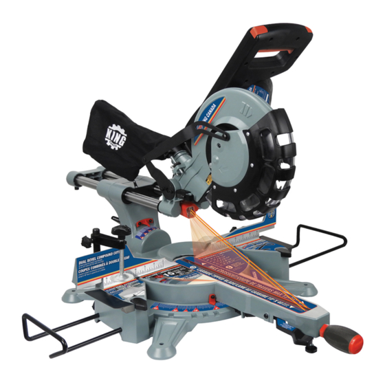
- Page 1 10” DUAL BEVEL SLIDING COMPOUND MITER SAW WITH TWIN LASER GUIDE MODEL: 8385NS INSTRUCTION MANUAL COPYRIGHT © 2020 ALL RIGHTS RESERVED BY KING CANADA TOOLS INC.
-
Page 2: Warranty Information
Please keep your dated proof of purchase for warranty and servicing purposes. REPLACEMENT PARTS Replacement parts for this product are available at our authorized King Canada service centers across Canada. Please use the 10 digit part numbers listed in this manual for all part orders where applicable. -
Page 3: General Safety Instructions
GENERAL SAFETY INSTRUCTIONS GENERAL POWER TOOL SAFETY WARNINGS switch on invites accidents. • Remove any adjusting key or wrench before turning the power WARNING: Read all safety warnings, instructions, illustrations and tool on. A wrench or a key left attached to a rotating part of the power specifications provided with this power tool. -
Page 4: Specific Safety Instructions
SPECIFIC SAFETY INSTRUCTIONS SAFETY INSTRUCTIONS FOR MITER SAWS • Do not use another person as a substitute for a table extension or as additional support. Unstable support for the workpiece can cause the blade to bind or the workpiece to shift during the cutting •... -
Page 5: Safety Symbols
SPECIFIC SAFETY INSTRUCTIONS ADDITIONAL SAFETY RULES FOR MITER SAWS continued... This may cause misalignment. Always lock the head assembly in the “DOWN” position and carry the saw by holding the base or lift it using • Never reach around or behind the saw blade. A blade can cause the carrying handle/support bracket. -
Page 6: Electrical Information
Do not look into the direct or reflected laser beam; can cause eye injury up to 50 feet (15m) away. Class 2 lasers are considered safe for accidental eye exposure. Do not look or stare into laser beam. This is not a toy. MODEL 8385NS Motor 15 Amp. Voltage... -
Page 7: Unpacking And Assembly
UNPACKING & ASSEMBLY UNPACKING Due to modern mass production techniques, it is unlikely that your King Canada Power tool is faulty or that a part is missing. If you find anything wrong, do not operate the tool until the parts have been replaced or the fault has been rectified. - Page 8 ADJUSTMENTS DUST BAG The dust bag (A) Fig.6 fits into the dust bag adaptor (B) at the rear of the saw head. For more efficient operation, empty the dust bag when it is no more than half full. This allows better air flow through the bag. BENCH MOUNTING The saw base has holes to facilitate bench mounting.
- Page 9 ADJUSTMENTS SETTING THE BLADE SQUARE WITH THE TABLE 1. Make sure that the electrical plug is removed from the main power supply. 2. Push the saw head down to its lowest position, then pull and turn the head release knob to hold the saw head in the transport position. 3.
- Page 10 ADJUSTMENTS & OPERATION USING THE TWIN LASER GUIDE SYSTEM The twin laser guide system is controlled by the laser guide push button switch (A) Fig.14 and will only turn on when the miter saw is plugged into a power source. Warning! Do not stare directly into the laser beams.
-
Page 11: Miter Cuts
ADJUSTMENTS & OPERATION TO MITER CUT/CROSSCUT continued..6. When cutting long pieces of lumber or molding, support the opposite end of the workpiece with a roller stand or with a work surface level with the saw table. 7. Lower the blade and align the cutting line on the workpiece with the edge of saw blade. 8. -
Page 12: Cutting Grooves
ADJUSTMENTS & OPERATION CUTTING GROOVES The depth of cut stop (Fig.9) is a feature which can be used for cutting grooves in a workpiece. In its normal position, the depth of cut stop (A) Fig.8 permits the saw blade to cut right through a workpiece. When the saw arm is lifted, the depth of cut stop (A) Fig.9 can be slid over towards the right so that the depth adjustment screw (B) contacts the stop as the saw arm is lowered. - Page 13 REPLACING/ INSTALLING BLADE REPLACING/INSTALLING BLADE DANGER! • Never attempt to use a blade larger than the stated capacity of the saw (10”). It will come into contact with the blade guards. • Never use a blade that is too thick to allow the outer blade flange to engage with the flats on the spindle.
-
Page 14: Maintenance
2 pan FIGURE 23 head screws. Carbon brush limit mark FIGURE 24 PARTS DIAGRAM & PARTS LISTS Refer to the Parts section of the King Canada web site for the most updated parts diagram and parts list.