
Related Manuals for King Canada 8324


Summary of Contents for King Canada 8324
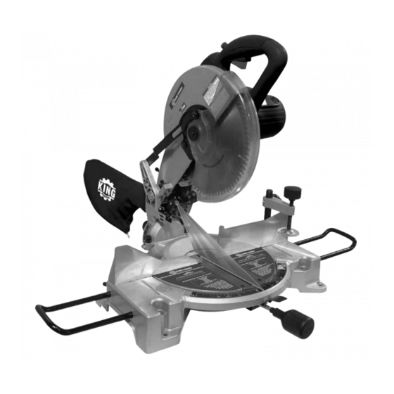
- Page 1 10” COMPOUND MITER SAW with *Enhanced Laser Effect MODEL: 8324 INSTRUCTION MANUAL COPYRIGHT © 2005 ALL RIGHTS RESERVED BY KING CANADA TOOLS INC.
-
Page 2: Proof Of Purchase
Warranty does not apply to defects due directly or indirectly to misuse, abuse, negligence or accidents, repairs or alterations and lack of maintenance. KING CANADA shall in no event be liable for death, injuries to persons or property or for incidental, special or consequential damages arising from the use of our products. -
Page 3: General Safety Instructions For Power Tools
GENERAL SAFETY INSTRUCTIONS FOR POWER TOOLS 1. KNOW YOUR TOOL 12. ALWAYS WEAR SAFETY GLASSES. Read and understand the owners manual and labels affixed to Always wear safety glasses (ANSI Z87.1). Everyday the tool. Learn its application and limitations as well as its eyeglasses only have impact resistant lenses, thet are NOT specific potential hazards. -
Page 4: Additional Safety Instructions
ADDITIONAL SAFETY INSTRUCTIONS FOR YOUR COMPOUND MITER SAW 1. WARNING: USE ONLY CROSS-CUTTING SAW BLADES. WHEN USING CARBIDE TIPPED BLADES, DO NOT USE 19. MAKE SURE blade is not contacting workpiece before switch is BLADES WITH DEEP GUILLETS AS THEY CAN DEFLECT turned on. -
Page 5: Tool Specifications
NO.16 26-50 FEET NO.14 51-100 FEET Not recommended FIGURE 2 TOOL SPECIFICATIONS Model ......................................8324 Voltage ......................................110V Input power ....................................15 Amp. Insulation class ................................Double insulation No load speed ..................................4,600 RPM Blade size..................................10” x 80 teeth Arbor size ......................................5/8” Miter table angles ..........................0 , 15 , 22.5... - Page 6 ASSEMBLY Your compound miter saw comes almost completely assembled, only the dust bag, table lock knob and extension wings must be assembled. ASSEMBLING DUST BAG 1. Slide dust bag assembly (A) Fig. 3, over dust spout (B) on rear of upper guard assembly, as shown.
-
Page 7: Operating Controls
OPERATING CONTROLS STARTING AND STOPPING SAW To turn the saw "ON" press in the safety button (A) and then pull the large trigger switch (B) Fig.7. To turn the saw "OFF" release trigger switch. FIGURE 7 LOCKING CUTTING ARM IN THE DOWN POSITION. When transporting the miter saw, the cutting arm should always be locked in the down position. - Page 8 ADJUSTMENTS ADJUSTING FENCE 90 DEGREES TO BLADE 1. DISCONNECT THE SAW FROM THE POWER SOURCE. 2. Place the cutting arm in the 90 degree straight cut-off position, as shown in Fig. 11, and tighten the table lock knob. 3. Using a square (A) Fig. 11, place one end of the square against the blade and the other end against the fence, as shown.
-
Page 9: Changing Batteries
ADJUSTMENTS DEPTH STOP ADJUSTMENT In its normal position, the depth of cut stop Fig.15 permits the saw blade to cut right through a workpiece. When the saw arm is lifted, the depth stop (A) Fig.16 can be pulled out so that the depth adjustment screw (B) contacts the stop as the saw arm is lowered. -
Page 10: Changing The Blade
CHANGING BLADE CHANGING THE BLADE WARNING: USE ONLY CROSS-CUTTING SAW BLADES. WHEN USING CARBIDE TIPPED BLADES, MAKE SURE THEY HAVE A 0 DEGREE OR A NEGATIVE HOOK ANGLE. DO NOT USE BLADES WITH DEEP GULLETS AS THEY CAN DEFLECT AND CONTACT GUARD. -
Page 11: Maintenance
If a brush needs replacement, replace both brushes. PARTS DIAGRAM & PARTS LISTS Refer to the Parts section of the King Canada web site for the most updated parts diagram and parts list.