
Related Manuals for King Canada KC-10TC


Summary of Contents for King Canada KC-10TC
-
Page 1: Instruction Manual
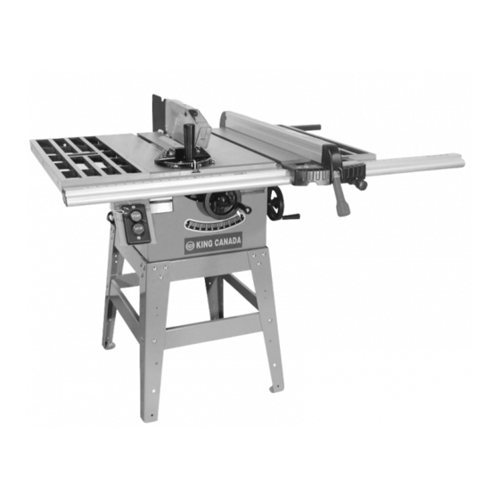
10” CONTRACTORS TABLE SAW MODEL: KC-10TC INSTRUCTION MANUAL COPYRIGHT © 2008 ALL RIGHTS RESERVED BY KING CANADA TOOLS INC. -
Page 2: Warranty
PROOF OF PURCHASE Please keep your dated proof of purchase for warranty and servicing purposes. REPLACEMENT PARTS Replacement parts for this Table Saw with new blade guard are available at our authorized King Canada service centers across Canada. LIMITED TOOL WARRANTY King Canada makes every effort to ensure that this product meets high quality and durability standards. -
Page 3: General Safety Instructions
GENERAL SAFETY INSTRUCTIONS FOR POWER TOOLS 1. KNOW YOUR TOOL 15. DISCONNECT TOOLS. Read and understand the owners manual and labels affixed to Before servicing, when changing accessories or attachments. the tool. Learn its application and limitations as well as its 16. -
Page 4: Table Of Contents
SPECIFIC SAFETY INSTRUCTIONS, SPECIFICATIONS & TABLE OF CONTENTS 1. ALWAYS USE A GUARD. 9. DIRECTION OF FEED. Always use a guard, splitter and anti-kickback fingers on all Feed work into the blade or cutter against the direction or “thru-sawing” operations. Thru-sawing operations are those rotation of the blade or cutter. -
Page 5: Assembly
ASSEMBLY TOOLS PROVIDED FOR ASSEMBLY 1. Arbor-blade guard bracket wrench. 2. 12mm combination wrench. 3. Two allen wrenches. ADDITIONAL TOOLS REQUIRED 1. Large flat-head screwdriver. 2. Phillips #1 point screwdriver Note: The use of sockets with a ratchet will lessen the assembly time required. - Page 6 ASSEMBLY ASSEMBLING GUIDE RAILS 1. Assemble the front and rear guide rails to the table using the special screws (A) and spacers (B), as shown in Fig.5. The guide rail with the calibrations goes on the front of the table and these calibrations are to be on the top side.
- Page 7 ASSEMBLY ASSEMBLING MOTOR, MOTOR PLATE AND GUARD BRACKET Make sure the motor is DISCONNECTED from the power source and assembled as follows: 1. Assemble the 2-1/2” carriage bolt (A) and washer (C) to the pulley guard bracket using nut (B) as shown in Fig.10. 2.
- Page 8 ASSEMBLY ASSEMBLING BELT AND PULLEY COVER 1. Assemble the V-belt to the motor and arbor pulleys. Using a straight edge, align the two pulleys as shown in Fig.15. If necessary move the motor and/or motor pulley for proper alignment. 2. Place spacer (A), washer (B) and wing nut (C) on screw as shown in Fig.16.
-
Page 9: Electrical Connections
ELECTRICAL CONNECTIONS & ADJUSTMENTS WARNING! ALL ELECTRICAL CONNECTIONS MUST BE DONE BY A QUALIFIED ELECTRICIAN. FAILURE TO COMPLY MAY RESULT IN SERIOUS INJURY! ALL ADJUSTMENTS OR REPAIRS MUST BE DONE WITH THE TABLE SAW DISCONNECTED FROM THE POWER SOURCE. FAILURE TO COMPLY MAY RESULT IN SERIOUS INJURY! CONNECTING SAW TO POWER SOURCE A separate electrical circuit should be used for your power tools. -
Page 10: Adjustments
ADJUSTMENTS BLADE RAISING AND TILTING MECHANISM To raise or lower the saw blade, loosen the lock knob (A), Fig.23 and turn the raising handwheel (B). With the exception of hollow ground blades. The blade should be raised 1/8’’ to 1/4’’ above the surface of the material being cut. -
Page 11: Operations
OPERATIONS REMOVING SAW BLADE When removing saw blades from the saw, make sure the saw is disconnected from the power source. Standing in front of the table saw, remove the table insert, place a block of wood against the front of the saw blade and using the arbor nut wrench, turn the arbor nut towards you. - Page 12 OPERATIONS If the ripped work is less than 3 inches wide, a push-stick should be used to complete the feed, as shown in Fig.29. A typical push-stick is shown in Fig.30, and can be easily made from scrap material. When ripping 2 inches or narrower, make an auxiliary guide and fasten it to the rip fence, and use a push-stick.
- Page 13 OPERATIONS It is necessary when using the moulding cutterhead to add wood- facing to one or both sides of the rip fence. The wood-facing is attached to the fence with wood screws. 3/4’’ stock is suitable for most work. Position the wood-facing over the cutterhead with the cutterhead below the surface of the table.
-
Page 14: Troubleshooting
TROUBLESHOOTING PROBLEM SOLUTION SAW WILL NOT START 1. Saw not plugged in. 1. Plug in saw. 2. Fuse blown or circuit breaker tripped. 2. Replace fuse or reset circuit breaker. 3. Cord damaged. 3. Have cord replaced by a certified electrician. 4.