Juniper QFX3600 Hardware Documentation
Hide thumbs
Also See for QFX3600:
- Hardware documentation (240 pages) ,
- Quick start (2 pages) ,
- Hardware documentation (669 pages)

Related Manuals for Juniper QFX3600


Summary of Contents for Juniper QFX3600
- Page 1 QFX3600 Device Hardware Documentation Published: 2013-07-03 Copyright © 2013, Juniper Networks, Inc.
- Page 2 Products made or sold by Juniper Networks or components thereof might be covered by one or more of the following patents that are owned by or licensed to Juniper Networks: U.S. Patent Nos. 5,473,599, 5,905,725, 5,909,440, 6,192,051, 6,333,650, 6,359,479, 6,406,312, 6,429,706, 6,459,579, 6,493,347, 6,538,518, 6,538,899, 6,552,918, 6,567,902, 6,578,186, and 6,590,785.
-
Page 3: Table Of Contents
Front Panel of a QFX3600 Device ........ - Page 4 Management Port Connector Pinouts for the QFX Series ....37 Interface Support for the QFX3600 Device ....... 37 Interface Specifications for QSFP+ DAC Breakout Cables for the QFX Series .
- Page 5 Installing the QFX3600 Device ........
- Page 6 Connecting the QFX3600 Device ........125...
- Page 7 Packing a QFX3600 or QFX3600-I Device or Component for Shipping ..179 Packing a QFX3600 or QFX3600-I Device for Shipping ....180 Packing QFX3600 or QFX3600-I Device Components for Shipping .
- Page 8 QFX3600 Device Hardware Documentation viii Copyright © 2013, Juniper Networks, Inc.
- Page 9 QFX3600 or QFX3600-I Device ........34...
- Page 10 Connecting the QFX3600 Device ........125...
- Page 11 Returning Hardware ..........177 Figure 42: Location of the Serial Number ID Label on a QFX3600 or QFX3600-I Device .
- Page 12 QFX3600 Device Hardware Documentation Copyright © 2013, Juniper Networks, Inc.
- Page 13 QFX3600 Overview ........
- Page 14 Installing the QFX3600 Device ........
-
Page 15: About The Documentation
® To obtain the most current version of all Juniper Networks technical documentation, see the product documentation page on the Juniper Networks website at http://www.juniper.net/techpubs/ If the information in the latest release notes differs from the information in the documentation, follow the product Release Notes. -
Page 16: Table 1: Notice Icons
[edit protocols directories; configuration hierarchy levels; hierarchy level. ospf area area-id] or labels on routing platform The console port is labeled CONSOLE components. < > (angle brackets) Enclose optional keywords or variables. stub <default-metric metric>; Copyright © 2013, Juniper Networks, Inc. -
Page 17: Documentation Feedback
Software release version (if applicable) Requesting Technical Support Technical product support is available through the Juniper Networks Technical Assistance Center (JTAC). If you are a customer with an active J-Care or JNASC support contract, Copyright © 2013, Juniper Networks, Inc. -
Page 18: Self-Help Online Tools And Resources
7 days a week, 365 days a year. Self-Help Online Tools and Resources For quick and easy problem resolution, Juniper Networks has designed an online self-service portal called the Customer Support Center (CSC) that provides you with the following features: Find CSC offerings: http://www.juniper.net/customers/support/... -
Page 19: Overview
PART 1 Overview QFX3600 Overview on page 3 Chassis on page 9 Cooling System and Airflow on page 13 Power Supply on page 17 Copyright © 2013, Juniper Networks, Inc. - Page 20 QFX3600 Device Hardware Documentation Copyright © 2013, Juniper Networks, Inc.
-
Page 21: Qfx3600 Overview
Layer 3 switching, routing, and security services. Junos OS is installed on the QFX3600 device’s 8-gigabyte (GB) internal flash drive. The same Junos OS code base that runs on QFX Series devices also runs on all Juniper Networks EX Series, J Series, M Series, MX Series, and T Series devices. -
Page 22: Hardware
Hardware The compact QFX3600 chassis is 1 rack unit (1 U) in size and designed to fit in industry-standard 19-inch rack-mount enclosures, as well as high-density server racks and container-based data center deployments. See... -
Page 23: Field-Replaceable Units For Qfx3600 And Qfx3600-I Devices
(QSFP+) transceivers. “Front Panel of a QFX3600 Device” on page If you are using the QFX3600 device as a Node device in a QFabric system, by default, four ports (labeled through ) are configured for uplink connections between your... -
Page 24: Understanding Redundancy Of Qfx3600 And Qfx3600-I Components And Functionality
Cooling system—QFX3600 and QFX3600-I devices have three fan trays. If a fan module on a fan tray fails and is unable to keep the QFX3600 device within the desired temperature thresholds, chassis alarms occur and the device may shut down. - Page 25 Chapter 1: QFX3600 Overview Cooling System and Airflow for QFX3600 and QFX3600-I Devices on page 13 Copyright © 2013, Juniper Networks, Inc.
- Page 26 QFX3600 Device Hardware Documentation Copyright © 2013, Juniper Networks, Inc.
-
Page 27: Chassis
Front Panel of a QFX3600 Device on page 10 Rear Panel of QFX3600 and QFX3600-I Devices on page 12 Chassis Physical Specifications for QFX3600 and QFX3600-I Devices The QFX3600 and QFX3600-I chassis is a rigid sheet-metal structure that houses the hardware components. Table 4 on page 9 summarizes the physical specifications of the QFX3600 and QFX3600-I chassis. -
Page 28: Front Panel Of A Qfx3600 Device
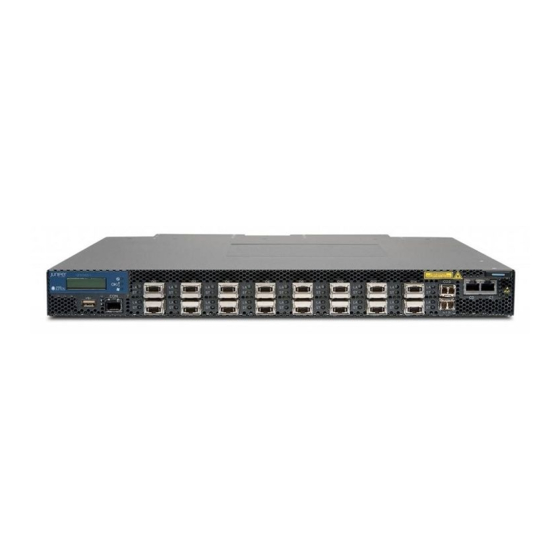
Access and uplink ports—The QFX3600 device has sixteen 40-Gbps ports labeled through that support quad small form-factor pluggable plus (QSFP+) transceivers. If you are using the QFX3600 device as a Node device in a QFabric system, by default, four ports (labeled through ) are configured for uplink connections between Copyright ©... -
Page 29: Figure 3: Qfx3600 Device Front Panel
Specifications for SFP, SFP+, and QSFP+ Transceivers for the QFX Series and “Interface Specifications for QSFP+ DAC Breakout Cables for the QFX Series” on page If you are using the QFX3600 device as a standalone switch, by default, all 16 QSFP+ ports ( through ) are configured as 40-Gigabit Ethernet (xle) ports. -
Page 30: Rear Panel Of Qfx3600 And Qfx3600-I Devices
Prevention of Electrostatic Discharge Damage on page 96 Installing and Removing QFX3600 or QFX3600-I Device Hardware Components on page 145 Rear Panel of QFX3600 and QFX3600-I Devices The rear panel of QFX3600 and QFX3600-I devices consists of the following components: Fan trays Grounding point Power supplies Figure 4 on page 12 shows the rear panel of a QFX3600 device. -
Page 31: Cooling System And Airflow
CHAPTER 3 Cooling System and Airflow Cooling System and Airflow for QFX3600 and QFX3600-I Devices on page 13 Cooling System and Airflow for QFX3600 and QFX3600-I Devices The cooling system in QFX3600 and QFX3600-I devices consist of three field-replaceable unit (FRU) fan trays with two fan modules each (see Figure 5 on page 13). -
Page 32: Figure 6: Fru-Side-To-Port-Side Airflow Through The Qfx3600 And Qfx3600-I
QFX3600 Device Hardware Documentation Table 5: Airflow Direction in QFX3600 and QFX3600-I Device Models Model Direction of Airflow QFX3600-16Q-AFI FRU-side-to-port-side QFX3600-16Q-AFO Port-side-to-FRU-side QFX3600-I-16Q-AFI FRU-side-to-port-side QFX3600-I-16Q-AFO Port-side-to-FRU-side In QFX3600 and QFX3600-I device models that have FRU-side-to-port-side airflow, the air intake to cool the chassis is located on the rear panel of the chassis, where the FRUs are installed. -
Page 33: Figure 7: Port-Side-To-Fru-Side Airflow Through The Qfx3600 And Qfx3600-I
Table 5 on page 14 determine your model’s airflow direction. Figure 8: Label Identifying Airflow Direction on Power Supply Handle Table 6 on page 16 lists QFX3600 and QFX3600-I device FRUs and their direction of airflow. Copyright © 2013, Juniper Networks, Inc. -
Page 34: Table 6: Airflow Direction In Qfx3600 And Qfx3600-I Device Frus
Rear Panel of QFX3600 and QFX3600-I Devices on page 12 Prevention of Electrostatic Discharge Damage on page 96 Installing a Fan Tray in a QFX3600 or QFX3600-I Device on page 149 Removing a Fan Tray from a QFX3600 or QFX3600-I Device on page 150 Fan Tray LED on a QFX3600 or QFX3600-I Device on page 167 Copyright ©... -
Page 35: Power Supply
CHAPTER 4 Power Supply AC Power Supply for a QFX3500, QFX3600, or QFX3600-I Device on page 17 DC Power Supply for a QFX3500, QFX3600, or QFX3600-I Device on page 19 Grounding Cable and Lug Specifications for QFX3600 and QFX3600-I Devices on page 21... -
Page 36: Figure 10: Label Identifying Airflow Direction On Power Supply Handle
AC Power Cord Specifications for a QFX3500, QFX3600, or QFX3600-I Device on Documentation page 54 AC Power Supply LEDs on a QFX3500, QFX3600, or QFX3600-I Device on page 167 Front Panel of a QFX3500 Device Field-Replaceable Units in a QFX3500 Device... -
Page 37: Dc Power Supply For A Qfx3500, Qfx3600, Or Qfx3600-I Device
(FRUs) that you can install in the device without powering off the device or disrupting the switching function. The DC power supply in QFX3500, QFX3600, and QFX3600-I devices is 650 W. NOTE: The V+ terminals are referred to as +RTN and V– terminals are referred to as –48 V in... -
Page 38: Figure 12: Dc Power Supply Faceplate
The power supplies have labels and arrows on the handles that depict the direction of airflow (see Figure 13 on page 20). The label denotes FRU-side-to-port-side airflow. denotes port-side-to FRU-side airflow. Figure 13: Label Identifying Airflow Direction on Power Supply Handle Copyright © 2013, Juniper Networks, Inc. -
Page 39: Table 8: Airflow Direction In Qfx3500, Qfx3600, And Qfx3600-I Device Dc
QFX3500, QFX3600, or QFX3600-I Device” on page 129. Related DC Power Supply LEDs on a QFX3500, QFX3600, or QFX3600-I Device on page 168 Documentation DC Power Specifications for a QFX3500 Device DC Power Specifications for a QFX3600 or QFX3600-I Device on page 55... - Page 40 The grounding lug provided accommodates 14–10 AWG (2–5.3 mm²) stranded wire. The grounding cable that you provide for a QFX3600 or QFX3600-I device must be 14 AWG (2 mm²), minimum 60° C wire, or as permitted by the local code.
-
Page 41: Planning
Site Preparation on page 25 Rack and Cabinet Requirements on page 31 Port and Interface Specifications on page 35 Cable Specifications on page 45 Planning Power Requirements on page 53 Compliance on page 57 Copyright © 2013, Juniper Networks, Inc. - Page 42 QFX3600 Device Hardware Documentation Copyright © 2013, Juniper Networks, Inc.
-
Page 43: Site Preparation
CHAPTER 5 Site Preparation Site Preparation Checklist for a QFX3600 or QFX3600-I Device on page 25 General Site Guidelines on page 26 Site Electrical Wiring Guidelines on page 27 Environmental Requirements and Specifications for QFX3600 and QFX3600-I Devices on page 29... -
Page 44: General Site Guidelines
General Safety Guidelines and Warnings on page 67 Documentation General Site Guidelines on page 26 Installing and Connecting a QFX3600 or QFX3600-I Device on page 115 General Site Guidelines This topic applies to hardware devices in the EX Series product family, which includes switches, the EX Series Redundant Power System (RPS), and the XRE200 External Routing Engine. -
Page 45: Site Electrical Wiring Guidelines
Environmental Requirements and Specifications for a QFX3100 Director Device Environmental Requirements and Specifications for a QFX3008-I Interconnect Device Environmental Requirements and Specifications for a QFX3500 Device Environmental Requirements and Specifications for QFX3600 and QFX3600-I Devices on page 29 Site Electrical Wiring Guidelines... - Page 46 AC Power Supply in an EX9204 Switch DC Power Supply in an EX9204 Switch AC Power Supply in an EX9208 Switch DC Power Supply in an EX9208 Switch AC Power Supply in an EX9214 Switch Copyright © 2013, Juniper Networks, Inc.
-
Page 47: Table 11: Qfx3600 And Qfx3600-I Device Environmental Tolerances
DC Power Supply for a QFX3500, QFX3600, or QFX3600-I Device on page 19 Environmental Requirements and Specifications for QFX3600 and QFX3600-I Devices The QFX3600 and QFX3600-I devices must be installed in a rack or cabinet housed in a dry, clean, well-ventilated, and temperature-controlled environment. - Page 48 Articles 110-16, 110-17, and 110-18 of the National Electrical Code, ANSI/NFPA 70. Related Clearance Requirements for Airflow and Hardware Maintenance for a QFX3600 or Documentation QFX3600-I Device on page 33 Installing and Connecting a QFX3600 or QFX3600-I Device on page 115...
-
Page 49: Rack And Cabinet Requirements
Clearance Requirements for Airflow and Hardware Maintenance for a QFX3600 or QFX3600-I Device on page 33 Rack Requirements for a QFX3600 or QFX3600-I Device QFX3600 and QFX3600-I devices are designed to be installed on two-post racks or four-post racks. Rack requirements consist of:... -
Page 50: Cabinet Requirements For A Qfx3600 Or Qfx3600-I Device
Clearance Requirements for Airflow and Hardware Maintenance for a QFX3600 or QFX3600-I Device on page 33 Mounting a QFX3600 or QFX3600-I Device on Four Posts in a Rack or Cabinet on page 120 Mounting a QFX3600 or QFX3600-I Device on Two Posts in a Rack or Cabinet on... -
Page 51: Clearance Requirements For Airflow And Hardware Maintenance For A Qfx3600 Or Qfx3600-I Device
Table 13: Cabinet Requirements for a QFX3600 or QFX3600-I Device Cabinet Requirement Guidelines Cabinet size and The minimum cabinet size for accommodating a QFX3600 device is 28 in. (71.1 cm) deep. Large clearance cabinets improve airflow and reduce the chance of overheating. Cabinet airflow... -
Page 52: Figure 14: Clearance Requirements For Airflow And Hardware Maintenance For
Leave at least 24 in. (61 cm) both in front of and behind the QFX3600 or QFX3600-I device. For service personnel to remove and install hardware components, you must leave adequate space at the front and back of the device. -
Page 53: Port And Interface Specifications
Interface Specifications for QSFP+ DAC Cables for the QFX Series on page 42 USB Port Specifications for the QFX Series The following Juniper Networks USB flash drives have been tested and are officially supported for the USB port in the QFX Series: RE-USB-1G-S—1-gigabyte (GB) USB flash drive (except QFX3100 Director device) -
Page 54: Console Port Connector Pinouts For The Qfx Series
Related Creating an Emergency Boot Device for a QFX Series Device on page 173 Documentation Performing a Recovery Installation on a QFX3008-I, QFX3600-I, QFX3600, or QFX3500 Device on page 175 Console Port Connector Pinouts for the QFX Series The console port (labeled... -
Page 55: Management Port Connector Pinouts For The Qfx Series
Related Management Port LEDs on a QFX3100 Director Device Documentation Management Port LEDs in the QFX3600 and QFX3600-I Device on page 164 Management Port LEDs on a QFX3500 Device Interface Support for the QFX3600 Device The QFX3600 device provides 16 QSFP+ ports, which support QSFP+ transceivers and QSFP+ DAC or DAC breakout cables. -
Page 56: Table 16: Supported Transceivers For The Qfx3600 Device
You can use SFP transceivers to connect the QFX3600 device to a management network, or the control plane and management network of a QFabric system. The 1000BASE-SX Gigabit Ethernet SFP module (QFX-SFP-1GE-SX) is supported in the SFP management ports labeled . -
Page 57: Table 17: Supported Dac And Dac Breakout Cables For The Qfx3600 Device
Specifications for QSFP+ DAC Breakout Cables for the QFX Series” on page 40 “Interface Specifications for QSFP+ DAC Cables for the QFX Series” on page 42 Table 17: Supported DAC and DAC Breakout Cables for the QFX3600 Device QFX3600 Node Device in QFX3600 Device as... -
Page 58: Interface Specifications For Qsfp+ Dac Breakout Cables For The Qfx Series
For information about which transceivers are supported on QFX Series devices, see the following topics: Interface Support for the QFX3600 Device on page 37 Interface Support for the QFX3500 Device The cables are hot-removable and hot-insertable. A breakout cable consists of a QSFP+ transceiver on one end and four SFP+ transceivers on the other end. -
Page 59: Table 19: Qsfp+ Dac Breakout Cable Specifications
100 ohms Time delay 4.3 nsec/m Length 3 m (9.9 ft) Related Interface Specifications for SFP, SFP+, and QSFP+ Transceivers for the QFX Series Documentation Interface Specifications for SFP+ DAC Cables for the QFX Series Copyright © 2013, Juniper Networks, Inc. -
Page 60: Interface Specifications For Qsfp+ Dac Cables For The Qfx Series
QFX3600-I and QFX3600 or QFX3500 Node device, the interface is automatically configured to operate at 40 Gbps. If you use the QSFP+ DAC cable to interconnect a QFX3600 Node device with another device, the interface is automatically configured to operate as four 10-Gigabit Ethernet interfaces over one cable. -
Page 61: Table 21: Interface Specifications For Qsfp+ Dac Cables
Cable type Twinax Wire AWG 30 AWG Minimum cable bend radius 1 in. (2.54 cm) Cable characteristic impedance 100 ohms Crosstalk between pairs 1% maximum Time delay 4.3 nsec/m Length 1 m (3.3 ft) Copyright © 2013, Juniper Networks, Inc. - Page 62 Interface Specifications for QSFP+ DAC Breakout Cables for the QFX Series on page 40 Installing a Transceiver in a QFX Series Device on page 154 Removing a Transceiver from a QFX Series Device on page 153 Copyright © 2013, Juniper Networks, Inc.
-
Page 63: Cable Specifications
The 40-Gigabit Ethernet QSFP+ transceivers that connect Node devices to Interconnect devices in a QFabric system use 12-ribbon multimode fiber crossover cable with female MTP connectors. The fiber can be either OM3 or OM4. These cables are not sold by Juniper Networks. -
Page 64: Table 23: Qsfp+ Mtp Fiber-Optic Crossover Cable Pinouts
QFX3600 Device Hardware Documentation Table 22: QSFP+ MTP Cable Signals (continued) Fiber Signal Tx2 (Transmit) Tx3 (Transmit) Unused Unused Unused Unused Rx3 (Receive) Rx2 (Receive) Rx1 (Receive) Rx0 (Receive) Table 23: QSFP+ MTP Fiber-Optic Crossover Cable Pinouts Copyright © 2013, Juniper Networks, Inc. -
Page 65: Table 24: Cable Specifications For Console And Management Connections For The Qfx Series
Management Port Connector Pinouts for the QFX Series on page 37 Connecting a QFX Series Device to a Management Console on page 133 Connecting a QFX3600 Device to a Network for Out-of-Band Management on page 134 Connecting a QFX3500 Device to a Network for Out-of-Band Management... -
Page 66: Signal Loss In Multimode And Single-Mode Fiber-Optic Cable
An efficient optical data link must have enough light to exceed the minimum power that the receiver requires to operate within its specifications. In addition, the total dispersion must be within the limits specified for the type of link in Telcordia Technologies document Copyright © 2013, Juniper Networks, Inc. -
Page 67: Calculating The Fiber-Optic Cable Power Budget For A Qfx Series Device
Calculate the link's power margin when planning fiber-optic cable layout and distances to ensure that fiber-optic connections have sufficient signal power to overcome system losses and still satisfy the minimum input requirements of the receiver for the required Copyright © 2013, Juniper Networks, Inc. -
Page 68: Table 25: Estimated Values For Factors Causing Link Loss
2 km: 2 km (1 dBm/km) = 2 dBm Single-mode—0.5 dBm/km This example assumes the link is 2 km long. Fiber attenuation for 2 km: 2 km (0.5 dBm/km) = 1 dBm Clock Recovery Module 1 dBm 1 dBm (CRM) Copyright © 2013, Juniper Networks, Inc. - Page 69 Also, the power margin value does not exceed the maximum receiver input power. Refer to the specifications for your receiver to find the maximum receiver input power. Related Understanding QFX Series Fiber-Optic Cable Signal Loss, Attenuation, and Dispersion Documentation on page 47 Copyright © 2013, Juniper Networks, Inc.
- Page 70 QFX3600 Device Hardware Documentation Copyright © 2013, Juniper Networks, Inc.
-
Page 71: Planning Power Requirements
AC Power Cord Specifications for a QFX3500, QFX3600, or QFX3600-I Device on Documentation page 54 AC Power Supply for a QFX3500, QFX3600, or QFX3600-I Device on page 17 General Safety Guidelines and Warnings on page 67 General Electrical Safety Guidelines and Warnings on page 95... -
Page 72: Table 27: Ac Power Cord Specifications
QFX3600 Device Hardware Documentation AC Power Cord Specifications for a QFX3500, QFX3600, or QFX3600-I Device Detachable AC power cords are shipped with the chassis, if you include them as part of your order. The coupler is type C13 as described by International Electrotechnical Commission (IEC) standard 60320. -
Page 73: Dc Power Specifications For A Qfx3600 Or Qfx3600-I Device
Maximum power consumption 341 W Related DC Power Supply for a QFX3500, QFX3600, or QFX3600-I Device on page 19 Documentation DC Power Supply LEDs on a QFX3500, QFX3600, or QFX3600-I Device on page 168 Copyright © 2013, Juniper Networks, Inc. - Page 74 QFX3600 Device Hardware Documentation Copyright © 2013, Juniper Networks, Inc.
-
Page 75: Compliance
VCCI Regulations For Voluntary Control Measures of radio interference generated by Information Technology Equipment, V-3 and V-4 dated April 2011 (Class A). EN 300 386, V1.5.1 (2010-10), Class A TEC/EMI/TEL-001/01/FEB-09, Class A EN 61000-3-2 Power Line Harmonics EN 61000-3-3 Voltage Fluctuations and Flicker Copyright © 2013, Juniper Networks, Inc. -
Page 76: Compliance Statements For Emc Requirements For The Qfx Series
CAUTION: Users should not attempt to make electrical ground connections by themselves, but should contact the appropriate inspection authority or an electrician, as appropriate. Copyright © 2013, Juniper Networks, Inc. -
Page 77: European Community
Operation of this equipment in a residential area is likely to cause harmful interference in which case the user will be required to correct the interference at his own expense. Copyright © 2013, Juniper Networks, Inc. -
Page 78: Nonregulatory Environmental Standards
The equipment is suitable for installation as part of the Common Bonding Network (CBN). The equipment is suitable for installation in a central office (CO). Related Agency Approvals for the QFX Series on page 57 Documentation Declaration of Conformity for QFX Series Devices on page 61 Copyright © 2013, Juniper Networks, Inc. -
Page 79: Declaration Of Conformity For Qfx Series Devices
Chapter 10: Compliance Declaration of Conformity for QFX Series Devices Copyright © 2013, Juniper Networks, Inc. - Page 80 QFX3600 Device Hardware Documentation Copyright © 2013, Juniper Networks, Inc.
- Page 81 Chapter 10: Compliance Copyright © 2013, Juniper Networks, Inc.
- Page 82 QFX3600 Device Hardware Documentation Related Agency Approvals for the QFX Series on page 57 Documentation Compliance Statements for EMC Requirements for the QFX Series on page 58 Copyright © 2013, Juniper Networks, Inc.
-
Page 83: Safety
PART 3 Safety General Safety Information on page 67 Radiation and Laser Warnings on page 73 Installation and Maintenance Safety Information on page 79 Power and Electrical Safety Information on page 95 Copyright © 2013, Juniper Networks, Inc. - Page 84 QFX3600 Device Hardware Documentation Copyright © 2013, Juniper Networks, Inc.
-
Page 85: General Safety Information
Do not perform any actions that create a potential hazard to people or make the equipment unsafe. Never attempt to lift an object that is too heavy for one person to handle. Never install or manipulate wiring during electrical storms. Copyright © 2013, Juniper Networks, Inc. -
Page 86: Definitions Of Safety Warning Levels
The documentation uses the following levels of safety warnings (there are two “Warning” formats): NOTE: You might find this information helpful in a particular situation, or you might overlook this important information if it was not highlighted in a Note. Copyright © 2013, Juniper Networks, Inc. - Page 87 å unngå ulykker. Aviso Este símbolo de aviso indica perigo. Encontra-se numa situação que lhe poderá causar danos físicos. Antes de começar a trabalhar com qualquer equipamento, familiarize-se com os perigos relacionados com circuitos Copyright © 2013, Juniper Networks, Inc.
-
Page 88: Fire Safety Requirements
In addition, you should establish procedures to protect your equipment in the event of a fire emergency. Juniper Networks products should be installed in an environment suitable for electronic equipment. We recommend that fire suppression equipment be available in the event of a fire in the vicinity of the equipment and that all local fire, safety, and electrical codes and ordinances be observed when you install and operate your equipment. -
Page 89: Qualified Personnel Warning
To keep warranties effective, do not use a dry chemical fire extinguisher to control a fire at or near a Juniper Networks switch or other network device provided by Juniper. If a dry chemical fire extinguisher is used, the unit is no longer eligible for coverage under a service agreement. -
Page 90: Warning Statement For Norway And Sweden
The equipment must be connected to an earthed mains socket-outlet. Advarsel Apparatet skal kobles til en jordet stikkontakt. Varning! Apparaten skall anslutas till jordat nätuttag. Related General Safety Guidelines and Warnings on page 67 Documentation Copyright © 2013, Juniper Networks, Inc. -
Page 91: Radiation And Laser Warnings
Strahlungen auszusetzen, und starren Sie nicht in die Öffnungen! Avvertenza Quando i cavi in fibra non sono inseriti, radiazioni invisibili possono essere emesse attraverso l'apertura della porta. Evitate di esporvi alle radiazioni e non guardate direttamente nelle aperture. Copyright © 2013, Juniper Networks, Inc. -
Page 92: Laser And Led Safety Guidelines And Warnings For The Qfx Series
Class 1M Laser Radiation Warning on page 75 Class 1 Laser Product Warning on page 75 Class 1 LED Product Warning on page 76 Laser Beam Warning on page 76 Unterminated Fiber-Optic Cable Warning on page 77 Copyright © 2013, Juniper Networks, Inc. -
Page 93: General Laser Safety Guidelines
Varning! Laserprodukter av Klass 1M (IEC). Class 1M Laser Radiation Warning WARNING: Class 1M laser radiation when open. Do not view directly with optical instruments. Class 1 Laser Product Warning WARNING: Class 1 laser product. Copyright © 2013, Juniper Networks, Inc. -
Page 94: Class 1 Led Product Warning
Do not stare into the laser beam or view it directly with optical instruments. Waarschuwing Niet in de straal staren of hem rechtstreeks bekijken met optische instrumenten. Varoitus Älä katso säteeseen äläkä tarkastele sitä suoraan optisen laitteen avulla. Copyright © 2013, Juniper Networks, Inc. -
Page 95: Unterminated Fiber-Optic Cable Warning
à une distance inférieure à 100 mm peut poser des risques pour les yeux. Warnung Eine unsichtbare Laserstrahlung kann vom Ende des nicht angeschlossenen Glasfaserkabels oder Steckers ausgestrahlt werden. Nicht in den Laserstrahl schauen oder diesen mit einem optischen Instrument direkt Copyright © 2013, Juniper Networks, Inc. - Page 96 (t.ex. lupper, förstoringsglas och mikroskop) från ett avstånd på 100 mm kan skada ögonen. Related General Safety Guidelines and Warnings on page 67 Documentation Radiation from Open Port Apertures Warning on page 73 Installation Instructions Warning on page 79 Grounded Equipment Warning on page 88 Copyright © 2013, Juniper Networks, Inc.
-
Page 97: Installation And Maintenance Safety Information
Installation and Maintenance Safety Information Installation Instructions Warning on page 79 Chassis Lifting Guidelines for a QFX3600 or QFX3600-I Device on page 81 Restricted Access Warning on page 81 Ramp Warning on page 83 Rack-Mounting and Cabinet-Mounting Warnings on page 84... - Page 98 Connecting DC Power to an EX6200 Switch Connecting DC Power to an EX8200 Switch Connecting DC Power to an EX9204 Switch Connecting DC Power to an EX9208 Switch Connecting DC Power to an EX9214 Switch Copyright © 2013, Juniper Networks, Inc.
-
Page 99: Chassis Lifting Guidelines For A Qfx3600 Or Qfx3600-I Device
Chassis Lifting Guidelines for a QFX3600 or QFX3600-I Device The weight of a fully loaded QFX3600 or QFX3600-I device chassis is approximately 20.5 lb (9.3 kg). Observe the following guidelines for lifting and moving a QFX3600 or QFX3600-I device: Before installing a QFX3600 or QFX3600-I device, read the guidelines in “Site... - Page 100 Copyright © 2013, Juniper Networks, Inc.
-
Page 101: Ramp Warning
Varning! Använd inte ramp med en lutning på mer än 10 grader. Related General Safety Guidelines and Warnings on page 67 Documentation Installation Instructions Warning on page 79 Grounded Equipment Warning on page 88 Copyright © 2013, Juniper Networks, Inc. -
Page 102: Rack-Mounting And Cabinet-Mounting Warnings
De onderstaande richtlijnen worden verstrekt om uw veiligheid te verzekeren: De Juniper Networks switch moet in een stellage worden geïnstalleerd die aan een bouwsel is verankerd. Dit toestel dient onderaan in het rek gemonteerd te worden als het toestel het enige in het rek is. - Page 103 Les directives ci-dessous sont destinées à assurer la protection du personnel: Le rack sur lequel est monté le Juniper Networks switch doit être fixé à la structure du bâtiment. Si cette unité constitue la seule unité montée en casier, elle doit être placée dans le bas.
- Page 104 QFX3600 Device Hardware Documentation Il Juniper Networks switch deve essere installato in un telaio, il quale deve essere fissato alla struttura dell'edificio. Questa unità deve venire montata sul fondo del supporto, se si tratta dell'unica unità da montare nel supporto.
- Page 105 Chapter 13: Installation and Maintenance Safety Information El Juniper Networks switch debe instalarse en un bastidor fijado a la estructura del edificio. Colocar el equipo en la parte inferior del bastidor, cuando sea la única unidad en el mismo. Cuando este equipo se vaya a instalar en un bastidor parcialmente ocupado, comenzar la instalación desde la parte inferior hacia la superior colocando...
-
Page 106: Grounded Equipment Warning
Mounting a QFX3008-I Interconnect Device on a Rack or Cabinet Using a Mechanical Lift Mounting a QFX3600 or QFX3600-I Device on Four Posts in a Rack or Cabinet on page 120 Mounting a QFX3600 or QFX3600-I Device on Two Posts in a Rack or Cabinet on... -
Page 107: Maintenance And Operational Safety Guidelines And Warnings
Ne la remplacer que par une pile de type semblable ou équivalent, recommandée par le fabricant. Jeter les piles usagées conformément aux instructions du fabricant. Warnung Bei Einsetzen einer falschen Batterie besteht Explosionsgefahr. Ersetzen Sie die Batterie nur durch den gleichen oder vom Hersteller Copyright © 2013, Juniper Networks, Inc. -
Page 108: Jewelry Removal Warning
ôter tout bijou (anneaux, colliers et montres compris). Lorsqu'ils sont branchés à l'alimentation et reliés à la terre, les objets métalliques chauffent, ce qui peut provoquer des blessures graves ou souder l'objet métallique aux bornes. Copyright © 2013, Juniper Networks, Inc. -
Page 109: Lightning Activity Warning
Varoitus Älä työskentele järjestelmän parissa äläkä yhdistä tai irrota kaapeleita ukkosilmalla. Attention Ne pas travailler sur le système ni brancher ou débrancher les câbles pendant un orage. Copyright © 2013, Juniper Networks, Inc. -
Page 110: Operating Temperature Warning
6 in. (15.2 cm) of clearance around the ventilation openings. Waarschuwing Om te voorkomen dat welke switch van de Juniper Networks router dan ook oververhit raakt, dient u deze niet te bedienen op een plaats waar de maximale aanbevolen omgevingstemperatuur van 40°... -
Page 111: Product Disposal Warning
15,2 cm à volta das aberturas de ventilação. ¡Atención! Para impedir que un encaminador de la serie Juniper Networks switch se recaliente, no lo haga funcionar en un área en la que se supere la temperatura ambiente máxima recomendada de 40°... - Page 112 Laser and LED Safety Guidelines and Warnings for EX Series Switches Laser and LED Safety Guidelines and Warnings for the QFX Series on page 74 Installation Instructions Warning on page 79 Grounded Equipment Warning on page 88 Copyright © 2013, Juniper Networks, Inc.
-
Page 113: Power And Electrical Safety Information
The intrabuilding ports on the device are suitable for connection to intrabuilding or unexposed wiring or cabling only. The addition of primary protectors is not sufficient protection for connecting these interfaces metallically to OSP wiring. Copyright © 2013, Juniper Networks, Inc. -
Page 114: Prevention Of Electrostatic Discharge Damage
DC Power Electrical Safety Guidelines on page 101 Prevention of Electrostatic Discharge Damage This topic applies to hardware devices in the EX Series product family, which includes switches, the EX Series Redundant Power System (RPS), and the XRE200 External Routing Engine. Copyright © 2013, Juniper Networks, Inc. -
Page 115: Figure 16: Place A Component Into An Antistatic Bag
(see Figure 16 on page 97). If you are returning a component, place it in an antistatic bag before packing it. Figure 16: Place a Component into an Antistatic Bag Copyright © 2013, Juniper Networks, Inc. -
Page 116: Ac Power Electrical Safety Guidelines
See QFX3008-I Interconnect Device Overview for the ESD point location. See Front Panel of a QFX3500 Device for the ESD point location. Front Panel of a QFX3600 Device on page 10 for the ESD point location. Physical Description of a Redundant Power System... - Page 117 Connecting AC Power to an EX3300 Switch Connecting AC Power to an EX4200 Switch Connecting AC Power to an EX4500 Switch Connecting AC Power to an EX4550 Switch Connecting AC Power to an EX6200 Switch Copyright © 2013, Juniper Networks, Inc.
-
Page 118: Ac Power Disconnection Warning
Connecting AC Power to a QFX3008-I Interconnect Device with Three-Phase Wye Wiring Trays Connecting AC Power to a QFX3500, QFX3600, or QFX3600-I Device on page 127 AC Power Disconnection Warning This topic applies to hardware devices in the EX Series product family, which includes switches, the EX Series Redundant Power System (RPS), and the XRE200 External Routing Engine. -
Page 119: Dc Power Electrical Safety Guidelines
DC Power Electrical Safety Guidelines This topic applies to hardware devices in the EX Series product family, which includes switches and the XRE200 External Routing Engine. This topic also applies to hardware devices in the QFX Series. Copyright © 2013, Juniper Networks, Inc. - Page 120 Minimum of 100 A at –48 VDC for EX8216 switches Minimum of 7 A at –48 VDC for QFX3500 devices Minimum of 8 A at –48 VDC for QFX3600 devices Incorporate an easily accessible disconnect device into the facility wiring. Be sure to connect the ground wire or conduit to a solid office earth ground.
-
Page 121: Dc Power Disconnection Warning
Connecting DC Power to an EX9214 Switch Connecting DC Power to an XRE200 External Routing Engine Connecting DC Power to a QFX3500, QFX3600, or QFX3600-I Device on page 129 DC Power Disconnection Warning This topic applies to hardware devices in the EX Series product family, which includes switches and the XRE200 External Routing Engine. - Page 122 Varning! Innan du utför någon av följande procedurer måste du kontrollera att strömförsörjningen till likströmskretsen är bruten. Kontrollera att all strömförsörjning är BRUTEN genom att slå AV det överspänningsskydd som skyddar likströmskretsen och tejpa fast överspänningsskyddets omkopplare i FRÅN-läget. Copyright © 2013, Juniper Networks, Inc.
-
Page 123: Dc Power Grounding Requirements And Warning
Aviso Ao instalar a unidade, a ligação à terra deverá ser sempre a primeira a ser ligada, e a última a ser desligada. ¡Atención! Al instalar el equipo, conectar la tierra la primera y desconectarla la última. Copyright © 2013, Juniper Networks, Inc. -
Page 124: Dc Power Wiring Sequence Warning
Warnung Die Stromzufuhr ist nur mit geeigneten Ringösen an das DC Netzteil anzuschliessen. Die richtige Anschlusssequenz ist: Erdanschluss zu Erdanschluss, +RTN zu +RTN und dann -48V zu -48V. Die richtige Sequenz zum Abtrennen der Stromversorgung ist -48V zu -48V, +RTN zu +RTN und Copyright © 2013, Juniper Networks, Inc. -
Page 125: Dc Power Wiring Terminations Warning
DC Power Wiring Terminations Warning on page 107 DC Power Wiring Terminations Warning This topic applies to hardware devices in the EX Series product family, which includes switches and the XRE200 External Routing Engine. Copyright © 2013, Juniper Networks, Inc. - Page 126 ¡Atención! Cuando se necesite hilo trenzado, utilizar terminales para cables homologados, tales como las de tipo "bucle cerrado" o "espada", con las lengüetas de conexión vueltas hacia arriba. Estos terminales deberán ser del Copyright © 2013, Juniper Networks, Inc.
-
Page 127: Multiple Power Supplies Disconnection Warning
This topic applies to hardware devices in the EX Series product family, which includes switches, the EX Series Redundant Power System (RPS), and the XRE200 External Routing Engine. This topic also applies to hardware devices in the QFX Series. Copyright © 2013, Juniper Networks, Inc. -
Page 128: Action To Take After An Electrical Accident
Use caution. Be aware of potentially hazardous conditions that could cause further injury. Disconnect power from the device. If possible, send another person to get medical aid. Otherwise, assess the condition of the victim, then call for help. Copyright © 2013, Juniper Networks, Inc. - Page 129 General Safety Guidelines and Warnings on page 67 Documentation General Electrical Safety Guidelines and Warnings on page 95 AC Power Electrical Safety Guidelines on page 98 DC Power Electrical Safety Guidelines on page 101 Copyright © 2013, Juniper Networks, Inc.
- Page 130 QFX3600 Device Hardware Documentation Copyright © 2013, Juniper Networks, Inc.
-
Page 131: Installing The Qfx3600 Device
PART 4 Installation Installing the QFX3600 Device on page 115 Connecting the QFX3600 Device on page 125 Performing Initial Configuration on page 137 Copyright © 2013, Juniper Networks, Inc. - Page 132 QFX3600 Device Hardware Documentation Copyright © 2013, Juniper Networks, Inc.
-
Page 133: Installing The Qfx3600 Device
116. Mount the device by following the instructions appropriate for your site: Mounting a QFX3600 or QFX3600-I Device on Two Posts in a Rack or Cabinet on page 117 Mounting a QFX3600 or QFX3600-I Device on Four Posts in a Rack or Cabinet on... -
Page 134: Unpacking A Qfx3600 Or Qfx3600-I Device
QFX3600 Device Hardware Documentation If you are using the QFX3600-I device as an Interconnect device in a QFX3000-M QFabric system, see QFX3000-M QFabric System Installation Overview for information about the steps to install and configure your QFX3000-M QFabric system. Related... -
Page 135: Cabinet
Installing and Connecting a QFX3600 or QFX3600-I Device on page 115 Documentation Mounting a QFX3600 or QFX3600-I Device on Two Posts in a Rack or Cabinet You can front-mount, rear-mount, or mid-mount a QFX3600 or QFX3600-I device on two posts of a 19-in. rack or cabinet by using the mounting brackets provided with the device. - Page 136 QFX3600 Device Hardware Documentation Read “General Safety Guidelines and Warnings” on page 67, with particular attention “Chassis Lifting Guidelines for a QFX3600 or QFX3600-I Device” on page Remove the device from the shipping carton (see “Unpacking a QFX3600 or QFX3600-I Device” on page 116).
-
Page 137: Figure 17: Attaching The Front Or Rear Mounting Brackets To The Side Panel Of
Chapter 15: Installing the QFX3600 Device NOTE: If you use the front or rear mounting brackets (part number 540-038579), align the brackets such that the mounting ears are at the location where you want to mount the device. For example, if you want to front-mount the device, align the brackets such that the mounting ears are in the front of the device chassis. -
Page 138: Mounting A Qfx3600 Or Qfx3600-I Device On Four Posts In A Rack Or Cabinet
Mounting a QFX3600 or QFX3600-I Device on Four Posts in a Rack or Cabinet You can front-mount or rear-mount a QFX3600 or QFX3600-I device on four posts in a 19-in. rack or cabinet by using the mounting brackets and installation blades provided with the device. -
Page 139: Figure 19: Attaching The Installation Blades To The Rear Of The Rack
Chapter 15: Installing the QFX3600 Device WARNING: QFX3600 and QFX3600-I devices must be supported at all four corners. Mounting the chassis using only the front brackets damages the chassis and can result in serious bodily injury. CAUTION: If you are installing the QFX3600 or QFX3600-I device above 60 in. - Page 140 Tighten the screws. d. Ensure that the device chassis is level by verifying that all screws on one side of the rack are aligned with the screws on the other side. Copyright © 2013, Juniper Networks, Inc.
-
Page 141: Figure 20: Mounting The Device On Four-Posts
Documentation Connecting Earth Ground to QFX3600 or QFX3600-I Devices on page 126 Connecting AC Power to a QFX3500, QFX3600, or QFX3600-I Device on page 127 Connecting DC Power to a QFX3500, QFX3600, or QFX3600-I Device on page 129 Configuring a QFX3600 Device as a Standalone Switch on page 137... - Page 142 QFX3600 Device Hardware Documentation Copyright © 2013, Juniper Networks, Inc.
-
Page 143: Connecting The Qfx3600 Device
Connecting the QFX3600 Device Connecting Earth Ground to QFX3600 or QFX3600-I Devices on page 126 Connecting AC Power to a QFX3500, QFX3600, or QFX3600-I Device on page 127 Connecting DC Power to a QFX3500, QFX3600, or QFX3600-I Device on page 129... -
Page 144: Connecting Earth Ground To Qfx3600 Or Qfx3600-I Devices
(see Figure 21 on page 127). Before you connect earth ground to the protective earthing terminal of a QFX3600 or QFX3600-I device, ensure that a licensed electrician has attached an appropriate grounding lug to the grounding cable. CAUTION: Using a grounding cable with an incorrectly attached lug can damage the switch. -
Page 145: Connecting Ac Power To A Qfx3500, Qfx3600, Or Qfx3600-I Device
Documentation Grounded Equipment Warning on page 88 Connecting AC Power to a QFX3500, QFX3600, or QFX3600-I Device on page 127 Connecting DC Power to a QFX3500, QFX3600, or QFX3600-I Device on page 129 Connecting AC Power to a QFX3500, QFX3600, or QFX3600-I Device The power supply in QFX3500, QFX3600, and QFX3600-I devices is a hot-removable and hot-insertable field-replaceable unit (FRU). -
Page 146: Figure 22: Connecting An Ac Power Cord To An Ac Power Supply In A Qfx3500
Install the power supply in the chassis. For instructions on installing a power supply in a QFX3500 device, see Installing a Power Supply in a QFX3500 Device. For instructions on installing a power supply in a QFX3600 or QFX3600-I device, see “Installing a Power Supply in a QFX3600 or QFX3600-I Device”... -
Page 147: Connecting Dc Power To A Qfx3500, Qfx3600, Or Qfx3600-I Device
AC Power Supply for a QFX3500, QFX3600, or QFX3600-I Device on page 17 Documentation AC Power Supply LEDs on a QFX3500, QFX3600, or QFX3600-I Device on page 167 Connecting DC Power to a QFX3500, QFX3600, or QFX3600-I Device The power supply in QFX3500, QFX3600, and QFX3600-I devices is a hot-removable and hot-insertable field-replaceable unit (FRU). - Page 148 Install the power supply in the chassis. For instructions on installing a power supply in a QFX3500 device, see Installing a Power Supply in a QFX3500 Device. For instructions on installing a power supply in a QFX3600 or QFX3600-I device, see “Installing a Power Supply in a QFX3600 or QFX3600-I Device”...
- Page 149 Chapter 16: Connecting the QFX3600 Device The cable with very high resistance (indicating an open circuit) to chassis ground is negative (–) and will be installed on the V– (input) DC power input terminal. CAUTION: You must ensure that power connections maintain the proper polarity.
-
Page 150: Figure 24: Dc Power Supply Faceplate For A Qfx3500, Qfx3600 Or Qfx3600-I
Tighten the screws on the power supply terminals until snug using the screwdriver. Do not overtighten—apply between 5 in-lb (0.56 Nm) and 6 in-lb (0.68 Nm) of torque to the screws. Figure 24: DC Power Supply Faceplate for a QFX3500, QFX3600 or QFX3600-I Device 1—... -
Page 151: Connecting A Qfx Series Device To A Management Console
DC Power Supply for a QFX3500, QFX3600, or QFX3600-I Device on page 19 Documentation DC Power Supply LEDs on a QFX3500, QFX3600, or QFX3600-I Device on page 168 Connecting a QFX Series Device to a Management Console The QFX Series has a console port with an RJ-45 connector. Use the console port to connect the device to a management console or to a console server. -
Page 152: Connecting A Qfx3600 Device To A Network For Out-Of-Band Management
Documentation Connecting a QFX3600 Device to a Network for Out-of-Band Management If you are using the QFX3600 device as a standalone switch, you can monitor and manage the QFX3600 device using a dedicated management channel. QFX3600 devices have four management ports; two ports (labeled... -
Page 153: Figure 28: Connecting A Qfx3600 Device To A Network For Out-Of-Band
To connect a QFX3600 device to a network for out-of-band management (see Figure 28 on page 135): Connect one end of the cable to one of the management ports on the QFX3600 device. Connect the other end of the cable to the management device (see Figure 28 on page 135). - Page 154 QFX3600 Device Hardware Documentation Copyright © 2013, Juniper Networks, Inc.
-
Page 155: Performing Initial Configuration
QFX3600 device through the console port using the command-line interface (CLI). If you are using the QFX3600 device as a Node device in a QFabric system, you instead perform the initial setup of a QFabric system on a QFX3100 Director device (see Performing the QFabric System Initial Setup on a QFX3100 Director Group). - Page 156 [edit] root@# set system services telnet NOTE: When Telnet is enabled, you cannot log in to a QFX3600 device through Telnet using root credentials. Root login is allowed only for SSH access. Commit the configuration to activate it on the device.
-
Page 157: Viewing System Information
PART 5 Maintenance Removing the Device on page 141 Replacing Components on page 145 Replacing Transceivers and Fiber-Optic Cables on page 153 Routine Maintenance on page 161 Viewing System Information on page 163 Copyright © 2013, Juniper Networks, Inc. - Page 158 QFX3600 Device Hardware Documentation Copyright © 2013, Juniper Networks, Inc.
-
Page 159: Removing The Device
Removing the Device Powering Off a QFX3600 or QFX3600-I Device on page 141 Removing a QFX3600 or QFX3600-I Device from a Rack or Cabinet on page 143 Powering Off a QFX3600 or QFX3600-I Device Before you power off a QFX3600 or QFX3600-I device: Ensure that you have taken the necessary precautions to prevent electrostatic discharge (ESD) damage. - Page 160 “Connecting a QFX Series Device to a Management Console” on page 133. If you are using the QFX3600 device as a standalone switch, you can shut down the QFX3600 device from a management device on your out-of-band management network. For instructions about connecting a management device to the...
-
Page 161: Removing A Qfx3600 Or Qfx3600-I Device From A Rack Or Cabinet
Removing a QFX3600 or QFX3600-I Device from a Rack or Cabinet If you need to relocate an installed QFX3600 or QFX3600-I device, use the procedure described in this topic. (The remainder of this topic uses “rack” to mean “rack or cabinet.”) - Page 162 Transport the QFX3600 or QFX3600-I device to your desired new location. Related Mounting a QFX3600 or QFX3600-I Device on Two Posts in a Rack or Cabinet on Documentation page 117 Mounting a QFX3600 or QFX3600-I Device on Four Posts in a Rack or Cabinet on page 120 Copyright ©...
-
Page 163: Replacing Components
1 minute of removal to prevent chassis overheating. To install a power supply in a QFX3600 or QFX3600-I device, follow the instructions in “Installing a Power Supply in a QFX3600 or QFX3600-I Device” on page 146. -
Page 164: Installing A Power Supply In A Qfx3600 Or Qfx3600-I Device
(FRUs): you can remove and replace them without powering off the device or disrupting device functions. Before you install a power supply in a QFX3600 device, ensure that you have taken the necessary precautions to prevent electrostatic discharge (ESD) damage (see “Prevention... -
Page 165: Removing A Power Supply From A Qfx3600 Or Qfx3600-I Device
This note does not apply if you replace components with the same type of component. Related AC Power Supply for a QFX3500, QFX3600, or QFX3600-I Device on page 17 Documentation DC Power Supply for a QFX3500, QFX3600, or QFX3600-I Device on page 19... - Page 166 QFX3600 Device Hardware Documentation Before you remove a power supply from a QFX3600 or QFX3600-I device, ensure that you have taken the necessary precautions to prevent electrostatic discharge (ESD) damage (see “Prevention of Electrostatic Discharge Damage” on page 96). Ensure that you have the following parts and tools available to remove a power supply...
-
Page 167: Installing A Fan Tray In A Qfx3600 Or Qfx3600-I Device
(FRUs): you can remove and replace them without powering off the device or disrupting device functions. Before you install a fan tray in a QFX3600 or QFX3600-I device, ensure that you have taken the necessary precautions to prevent electrostatic discharge (ESD) damage (see “Prevention of Electrostatic Discharge Damage”... -
Page 168: Removing A Fan Tray From A Qfx3600 Or Qfx3600-I Device
(FRUs): you can remove and replace them without powering off the device or disrupting device functions. Before you remove a fan tray from a QFX3600 or QFX3600-I device, ensure that you have taken the necessary precautions to prevent electrostatic discharge (ESD) damage (see “Prevention of Electrostatic Discharge Damage”... -
Page 169: Figure 32: Removing A Fan Tray From A Qfx3600 Or Qfx3600-I Device
Documentation Field-Replaceable Units for QFX3600 and QFX3600-I Devices on page 5 Rear Panel of QFX3600 and QFX3600-I Devices on page 12 Installing a Fan Tray in a QFX3600 or QFX3600-I Device on page 149 Copyright © 2013, Juniper Networks, Inc. - Page 170 QFX3600 Device Hardware Documentation Copyright © 2013, Juniper Networks, Inc.
-
Page 171: Replacing Transceivers And Fiber-Optic Cables
Disconnecting a Fiber-Optic Cable from a QFX Series Device on page 156 Connecting a Fiber-Optic Cable to a QFX Series Device on page 157 Configuring the Port Type on QFX3600 Standalone Switches on page 159 Removing a Transceiver from a QFX Series Device The transceivers for the QFX Series are hot-removable and hot-insertable field-replaceable units (FRUs). -
Page 172: Installing A Transceiver In A Qfx Series Device
Installing a Transceiver in a QFX Series Device The transceivers for the QFX Series are hot-removable and hot-insertable field-replaceable units (FRUs). You can remove and replace them without powering off the device or disrupting device functions. Copyright © 2013, Juniper Networks, Inc. - Page 173 Remove the rubber safety cap when you are ready to connect the cable to the transceiver. WARNING: Do not look directly into a fiber-optic transceiver or into the ends of fiber-optic cables. Fiber-optic transceivers and fiber-optic cables connected to transceivers emit laser light that can damage your eyes. Copyright © 2013, Juniper Networks, Inc.
-
Page 174: Disconnecting A Fiber-Optic Cable From A Qfx Series Device
Connecting a Fiber-Optic Cable to a QFX Series Device on page 157 Disconnecting a Fiber-Optic Cable from a QFX Series Device The QFX Series has field-replaceable unit (FRU) optical transceivers to which you can connect fiber-optic cables. Copyright © 2013, Juniper Networks, Inc. -
Page 175: Connecting A Fiber-Optic Cable To A Qfx Series Device
Before you connect a fiber-optic cable to an optical transceiver installed in the QFX Series, ensure that you have taken the necessary precautions for safe handling of lasers (see “Laser and LED Safety Guidelines and Warnings for the QFX Series” on page 74). Copyright © 2013, Juniper Networks, Inc. - Page 176 Related Disconnecting a Fiber-Optic Cable from a QFX Series Device on page 156 Documentation Maintaining Fiber-Optic Cables in a QFX Series Device on page 161 Copyright © 2013, Juniper Networks, Inc.
-
Page 177: Configuring The Port Type On Qfx3600 Standalone Switches
Chapter 20: Replacing Transceivers and Fiber-Optic Cables Configuring the Port Type on QFX3600 Standalone Switches The QFX3600 standalone switch provides 16 40-Gbps QSFP+ ports. By default, all 16 ports operate as 40-Gigabit Ethernet (xle) ports. Optionally, you can choose to configure the 40-Gbps ports to operate as four 10-Gigabit Ethernet (xe) ports. - Page 178 For example, to delete the 10-Gigabit Ethernet port configuration for port Q4: [edit chassis fpc 0 pic 0] user@switch# delete xe port 4 Related Understanding Interface Naming Conventions Documentation Copyright © 2013, Juniper Networks, Inc.
-
Page 179: Routine Maintenance
Fiber Cleaner. Follow the directions in the cleaning kit you use. Related Connecting a Fiber-Optic Cable to a QFX Series Device on page 157 Documentation Disconnecting a Fiber-Optic Cable from a QFX Series Device on page 156 Copyright © 2013, Juniper Networks, Inc. - Page 180 QFX3600 Device Hardware Documentation Copyright © 2013, Juniper Networks, Inc.
-
Page 181: Viewing System Information
DC Power Supply LEDs on a QFX3500, QFX3600, or QFX3600-I Device on page 168 Chassis Status LEDs in the QFX3600 and QFX3600-I Device The front panel of the QFX3600 and QFX3600-I device has three LEDs on the right side of the management board, next to the LCD panel (see Figure 36 on page 163). -
Page 182: Management Port Leds In The Qfx3600 And Qfx3600-I Device
Off a QFX3600 or QFX3600-I Device” on page 141. Correct any site temperature issues, and allow the device to cool down. Power on the QFX3600 or QFX3600-I device and monitor the power supply and fan LEDs to help determine where the error is occurring. -
Page 183: Access Port And Uplink Port Leds On A Qfx3600 Or Qfx3600-I Device
Connecting a QFX3600 Device to a Network for Out-of-Band Management on page 134 Access Port and Uplink Port LEDs on a QFX3600 or QFX3600-I Device Each access port and uplink port in a QFX3600 device has two LEDs (see Figure 38 on page 166). -
Page 184: Figure 38: Leds On The Qsfp+ Access And Uplink Ports
The LEDs labeled Status LED in Figure 38 on page 166 indicate link status. Table 32 on page 166 describes the QSFP+ access port LEDs. Table 32: Access Port LEDs on QSFP+ Ports on a QFX3600 Device Color State Description Link/Activity Unlit No link is established, there is a fault, or the link is down. -
Page 185: Fan Tray Led On A Qfx3600 Or Qfx3600-I Device
Cooling System and Airflow for QFX3600 and QFX3600-I Devices on page 13 Documentation Installing a Fan Tray in a QFX3600 or QFX3600-I Device on page 149 Removing a Fan Tray from a QFX3600 or QFX3600-I Device on page 150 AC Power Supply LEDs on a QFX3500, QFX3600, or QFX3600-I Device Figure 40 on page 168 shows the location of the LEDs on the power supply. -
Page 186: Dc Power Supply Leds On A Qfx3500, Qfx3600, Or Qfx3600-I Device
Device AC OK DC OK Fault Table 35 on page 168 describes the LEDs on the AC power supplies. Table 35: AC Power Supply LEDs on a QFX3500, QFX3600, or QFX3600-I Device Color State Description AC OK Unlit The power supply is disconnected from power, or power is not coming into the power supply. -
Page 187: Figure 41: Dc Power Supply Faceplate On A Qfx3500, Qfx3600, Or Qfx3600-I
Do not connect the terminals to different sources. Table 36 on page 169 describes the LEDs on the DC power supplies. Table 36: DC Power Supply LEDs on a QFX3500, QFX3600, or QFX3600-I Device Name Color State... - Page 188 QFX3600 Device Hardware Documentation Table 36: DC Power Supply LEDs on a QFX3500, QFX3600, or QFX3600-I Device (continued) Name Color State Description Fault Amber On steadily An error has been detected in the power supply. Replace the power supply as soon as possible.
-
Page 189: Troubleshooting
PART 6 Troubleshooting Restoring Junos OS on page 173 Returning Hardware on page 177 Alarm Messages on page 183 Copyright © 2013, Juniper Networks, Inc. - Page 190 QFX3600 Device Hardware Documentation Copyright © 2013, Juniper Networks, Inc.
-
Page 191: Restoring Junos Os
In the following procedure, we assume that you are creating the emergency boot device on a QFX3500 device. You can create the emergency boot device on another Juniper Networks switch or router, or any PC or laptop that supports Linux. The steps you take to create the emergency boot device vary, depending on the device. - Page 192 Related USB Port Specifications for the QFX Series on page 35 Documentation Performing a Recovery Installation on a QFX3008-I, QFX3600-I, QFX3600, or QFX3500 Device on page 175 Performing a QFabric System Recovery Installation on the Director Group Copyright © 2013, Juniper Networks, Inc.
-
Page 193: Performing A Recovery Installation On A Qfx3008-I, Qfx3600-I, Qfx3600, Or Qfx3500 Device
Chapter 23: Restoring Junos OS Performing a Recovery Installation on a QFX3008-I, QFX3600-I, QFX3600, or QFX3500 Device If Junos OS on your device is damaged in some way that prevents the software from loading correctly, you may need to perform a recovery installation using an emergency boot device (for example, a USB flash drive) to restore the default factory installation. - Page 194 Create a new configuration as you did when the device was shipped from the factory, or restore the previously saved configuration file to the device. Related Creating an Emergency Boot Device for a QFX Series Device on page 173 Documentation Copyright © 2013, Juniper Networks, Inc.
-
Page 195: Returning Hardware
Series Device or Component on page 181 Returning a QFX3600 or QFX3600-I Device or Component for Repair or Replacement If you need to return a QFX3600 or QFX3600-I device or component to Juniper Networks for repair or replacement, follow this procedure: Determine the serial number of the component. -
Page 196: Component
CLI operational mode command. For the QFX3600-I show chassis hardware Interconnect device, or if you are using the QFX3600 device as a Node device in a QFabric system, you must first log in to the device using the request component login operational mode command, or connect directly to the device through the console port on the front panel. -
Page 197: Device
177 Packing a QFX3600 or QFX3600-I Device or Component for Shipping If you are returning a QFX3600 or QFX3600-I device or component to Juniper Networks for repair or replacement, pack the item as described in this topic. Before you pack a QFX3600 or QFX3600-I device or component: Ensure that you have taken the necessary precautions to prevent electrostatic discharge (ESD) damage. -
Page 198: Packing A Qfx3600 Or Qfx3600-I Device For Shipping
“Powering Off a QFX3600 or QFX3600-I Device” on page 141. Remove the cables that connect the QFX3600 or QFX3600-I device to all external devices. Remove all field-replaceable units (FRUs) from the device. Have one person support the weight of the device while another person unscrews and removes the mounting screws. -
Page 199: Contacting Customer Support To Obtain A Return Materials Authorization For A Qfx Series Device Or Component
Contacting Customer Support to Obtain a Return Materials Authorization for a QFX Series Device or Component If you are returning a QFX Series device or component to Juniper Networks for repair or replacement, obtain a Return Materials Authorization (RMA) from the Juniper Networks Technical Assistance Center (JTAC). - Page 200 Returning a QFX3600 or QFX3600-I Device or Component for Repair or Replacement on page 177 Packing a QFX3600 or QFX3600-I Device or Component for Shipping on page 179 Returning a QFX3500 Device or Component for Repair or Replacement Packing a QFX3500 Device or Component for Shipping...
-
Page 201: Alarm Messages
CHAPTER 25 Alarm Messages Understanding Alarms on page 183 Chassis Alarm Messages on a QFX3600 or QFX3600-I Device on page 184 Interface Alarm Messages on page 186 Understanding Alarms The QFX Series support different alarm types and severity levels. Table 37 on page 183 provides a list of alarm terms and definitions that may help you in monitoring the device. -
Page 202: Chassis Alarm Messages On A Qfx3600 Or Qfx3600-I Device
To view the chassis alarm message text remotely, use the show chassis lcd CLI command. Chassis alarms on QFX3600 and QFX3600-I devices have two severity levels: Major (red)—Indicates a critical situation on the device that has resulted from one of the conditions described in Table 38 on page 184. - Page 203 Chapter 25: Alarm Messages Table 38: QFX3600 and QFX3600-I Chassis Alarm Messages (continued) Component Alarm Type CLI Message Recommended Action Power supplies Major (red) The power supply airflow direction is the PEM pem-number Airflow not matching opposite of the chassis airflow direction.
-
Page 204: Interface Alarm Messages
(such as hot air blowing around the equipment) are not affecting the temperature sensor. Related Chassis Status LEDs in the QFX3600 and QFX3600-I Device on page 163 Documentation Configuring the Junos OS to Determine Conditions That Trigger Alarms on Different Interface Types... - Page 205 Chapter 25: Alarm Messages NOTE: If you configure a yellow alarm on the QFX3008-I Interconnect device, it will be handled as a red alarm. Related Understanding Alarms on page 183 Documentation Copyright © 2013, Juniper Networks, Inc.
- Page 206 QFX3600 Device Hardware Documentation Copyright © 2013, Juniper Networks, Inc.