Juniper QFX3000-G QFabric Deployment Manual
Hide thumbs
Also See for QFX3000-G QFabric:
- Hardware documentation (966 pages) ,
- Quick start manual (7 pages) ,
- Manual (472 pages)

Related Manuals for Juniper QFX3000-G QFabric


Summary of Contents for Juniper QFX3000-G QFabric
- Page 1 QFX3000-G QFabric System Deployment Guide Release 13.1 Modified: 2015-06-30 Copyright © 2015, Juniper Networks, Inc.
- Page 2 END USER LICENSE AGREEMENT The Juniper Networks product that is the subject of this technical documentation consists of (or is intended for use with) Juniper Networks software. Use of such software is subject to the terms and conditions of the End User License Agreement (“EULA”) posted at http://www.juniper.net/support/eula.html.
-
Page 3: Table Of Contents
QFabric System Hardware Architecture Overview ..... . 15 QFX3000-G QFabric System Features ......18 QFX3000-M QFabric System Features . - Page 4 QFX3000-G QFabric System Deployment Guide Understanding Node Devices ......... 24 Node Device Introduction .
- Page 5 Before You Begin ..........83 QFX3000-G QFabric System Installation Overview ..... . . 83 Understanding QFX3000-G QFabric System Hardware Configurations .
- Page 6 QFX3000-G QFabric System Deployment Guide AC Power Specifications for a QFX3008-I Interconnect Device with Single-Phase Wiring Trays ........... . 131 AC Power Specifications for a QFX3008-I Interconnect Device with Three-Phase Delta Wiring Trays .
- Page 7 Connecting DC Power to a QFX3500, QFX3600, or QFX3600-I Device ..220 Connecting a QFX Series Device to a Management Console ....223 Copyright © 2015, Juniper Networks, Inc.
- Page 8 System Control Plane Network ........264 Chapter 15 Cabling the Data Plane for the QFX3000-G QFabric System ..269 Connecting a QFX3600 Node Device to a QFX3008-I Interconnect Device . . . 269 Connecting a QFX3500 Node Device to a QFX3008-I Interconnect Device .
- Page 9 Converting the Device Mode for a QFabric System Component ... . . 277 Example: Configuring the Virtual Chassis for the QFX3000-G QFabric System Control Plane ..........283 Example: Configuring a Fiber-Based Control Plane for the QFX3000-G QFabric System .
- Page 10 QFX3000-G QFabric System Deployment Guide interconnect-device (Chassis) ........429 interconnect-device (Aliases) .
- Page 11 Performing a QFabric System Recovery Installation on the Director Group ..616 (Optional) Creating an Emergency Boot Device Using a Juniper Networks External Blank USB Flash Drive ....... . 617 Performing a Recovery Installation Using a Juniper Networks External USB Flash Drive with Preloaded Software .
- Page 12 QFX3000-G QFabric System Deployment Guide Copyright © 2015, Juniper Networks, Inc.
- Page 13 Chapter 10 Installing a QFX3008-I Interconnect Device ......155 Copyright © 2015, Juniper Networks, Inc. xiii...
- Page 14 QFX3000-G QFabric System Deployment Guide Figure 23: Installing Four-Post Mounting Shelf and Rear Support Bracket for QFX3008-I Interconnect Device Four-Post Rack or Cabinet Mounting ..161 Figure 24: Installing Spacer Bar and Shelves for QFX3008-I Interconnect Device Four-Post Rack or Cabinet Mounting .
- Page 15 QFX3000-G QFabric System ........
- Page 16 Ranges ............285 Figure 78: QFX3000-G QFabric System Control Plane—Director Group to Virtual Chassis Connections .
- Page 17 Table 19: Site Electrical Wiring Guidelines ....... . 91 Copyright © 2015, Juniper Networks, Inc.
- Page 18 QFX3000-G QFabric System Deployment Guide Table 20: QFX3100 Director Device Environmental Tolerances ....93 Table 21: QFX3008-I Interconnect Device Environmental Tolerances ..94 Table 22: QFX3500 Device Environmental Tolerances .
- Page 19 Chapter 13 Cabling a Copper-Based Control Plane for the QFX3000-G QFabric System ............225 Table 64: Virtual Chassis-to-Virtual Chassis Copper-Based Control Plane Port Assignments .
- Page 20 Table 76: Support for device mode options ......278 Table 77: QFX3000-G QFabric System Virtual Chassis Control Plane Port Assignments .
-
Page 21: About The Documentation
® To obtain the most current version of all Juniper Networks technical documentation, see the product documentation page on the Juniper Networks website at http://www.juniper.net/techpubs/ If the information in the latest release notes differs from the information in the documentation, follow the product Release Notes. -
Page 22: Merging A Full Example
QFX3000-G QFabric System Deployment Guide If the example configuration does not start at the top level of the hierarchy, the example is a snippet. In this case, use the command. These procedures are load merge relative described in the following sections. -
Page 23: Documentation Conventions
Table 2: Text and Syntax Conventions Convention Description Examples Bold text like this Represents text that you type. To enter configuration mode, type the configure command: user@host> configure Copyright © 2015, Juniper Networks, Inc. xxiii... - Page 24 QFX3000-G QFabric System Deployment Guide Table 2: Text and Syntax Conventions (continued) Convention Description Examples Fixed-width text like this Represents output that appears on the user@host> show chassis alarms terminal screen. No alarms currently active Italic text like this Introduces or emphasizes important A policy term is a named structure new terms.
-
Page 25: Documentation Feedback
7 days a week, 365 days a year. Self-Help Online Tools and Resources For quick and easy problem resolution, Juniper Networks has designed an online self-service portal called the Customer Support Center (CSC) that provides you with the following features: Find CSC offerings: http://www.juniper.net/customers/support/... -
Page 26: Opening A Case With Jtac
Download the latest versions of software and review release notes: http://www.juniper.net/customers/csc/software/ Search technical bulletins for relevant hardware and software notifications: http://kb.juniper.net/InfoCenter/ Join and participate in the Juniper Networks Community Forum: http://www.juniper.net/company/communities/ Open a case online in the CSC Case Management tool: http://www.juniper.net/cm/... -
Page 27: Overview
PART 1 Overview Before You Begin on page 3 Hardware Architecture Overview on page 15 Software Architecture Overview on page 31 Software Features on page 41 Licenses on page 77 Copyright © 2015, Juniper Networks, Inc. - Page 28 QFX3000-G QFabric System Deployment Guide Copyright © 2015, Juniper Networks, Inc.
-
Page 29: Before You Begin
Legacy Data Center Architecture on page 3 QFX Series QFabric System Architecture on page 5 Legacy Data Center Architecture Service providers and companies that support data centers are familiar with legacy multi-tiered architectures, as seen in Figure 1 on page Copyright © 2015, Juniper Networks, Inc. -
Page 30: Figure 1: Legacy Data Center Architecture
QFX3000-G QFabric System Deployment Guide Figure 1: Legacy Data Center Architecture The access layer connects servers and other devices to a Layer 2 switch and provides an entry point into the data center. Several access switches are in turn connected to intermediate Layer 2 switches at the aggregation layer (sometimes referred to as the distribution layer) to consolidate traffic. -
Page 31: Qfx Series Qfabric System Architecture
Chapter 1: Before You Begin QFX Series QFabric System Architecture In contrast to legacy multi-tiered data center architectures, the Juniper Networks QFX Series QFabric System architecture provides a simplified networking environment that solves the most challenging issues faced by data center operators. A fabric is a set of devices that act in concert to behave as a single switch. - Page 32 QFX3000-G QFabric System Deployment Guide Essentially, a QFabric system can be viewed as a single, nonblocking, low-latency switch that supports thousands of 10-Gigabit Ethernet ports or 2-Gbps, 4-Gbps, or 8-Gbps Fibre Channel ports to interconnect servers, storage, and the Internet across a high-speed, high-performance fabric.
-
Page 33: Understanding Qfabric System Terminology
The fabric manager Routing Engine runs on the Director group. infrastructure QFabric system services processed by the virtual Junos Routing Engines operating within the Director group. These services, such as fabric management and fabric control, support QFabric system functionality and high availability. Copyright © 2015, Juniper Networks, Inc. - Page 34 Interconnect device is a QFX3008-I Interconnect device. (See also Node device.) Junos Space Carrier-class network management system for provisioning, monitoring, and diagnosing Juniper Networks routing, switching, security, and data center platforms. network Node group Set of one to eight Node devices that connects to an external network.
- Page 35 Gigabit Ethernet. Also, there are four uplink connections to connect to Interconnect devices in a QFabric system. These uplinks use 40-Gbps quad small form-factor pluggable plus (QSFP+) interfaces. (See also QFX3500 switch.) Copyright © 2015, Juniper Networks, Inc.
- Page 36 (Interconnect devices), and finishes with the Node groups. Routing Engine Juniper Networks-proprietary processing entity that implements QFabric system control plane functions, routing protocols, system management, and user access. Routing Engines can be either physical or virtual entities.
-
Page 37: Understanding Interfaces On The Qfabric System
The four-level interface naming convention is: device-name:type-fpc/pic/port where device-name is the name of the Node device or Node group. The remainder of the naming convention elements are the same as those in the QFX3500 switch interface naming convention. Copyright © 2015, Juniper Networks, Inc. -
Page 38: Qsfp+ Interfaces
QFX3000-G QFabric System Deployment Guide An example of a four-level interface name is: node2:xe-0/0/2 QSFP+ Interfaces The QFX3500 Node device provides four 40-Gbps QSFP+ (quad small form-factor pluggable plus) interfaces (labeled through ) for uplink connections between your Node device and your Interconnect devices. - Page 39 Not supported on this port xe-0/0/32 xe-0/0/33 xe-0/0/34 xe-0/0/35 Not supported on this port xe-0/0/36 xe-0/0/37 xe-0/0/38 xe-0/0/39 Not supported on this port xe-0/0/40 xe-0/0/41 xe-0/0/42 xe-0/0/43 Not supported on this port xe-0/0/44 xe-0/0/45 xe-0/0/46 xe-0/0/47 Copyright © 2015, Juniper Networks, Inc.
-
Page 40: Link Aggregation
QFX3000-G QFabric System Deployment Guide Table 4: QFX3600 Node Device Port Mappings (continued) 40-Gigabit Data Plane Uplink Port Number Interfaces 10-Gigabit Ethernet Interfaces Not supported on this port xe-0/0/48 xe-0/0/49 xe-0/0/50 xe-0/0/51 Not supported on this port xe-0/0/52 xe-0/0/53 xe-0/0/54... -
Page 41: Hardware Architecture Overview
Supported Platforms QFabric System QFabric System Hardware Architecture Overview on page 15 QFX3000-G QFabric System Features on page 18 QFX3000-M QFabric System Features on page 18 QFabric System Hardware Architecture Overview The QFabric system is a single-layer networking tier that connects servers and storage devices to one another across a high-speed, unified core fabric. -
Page 42: Figure 3: Qfabric System Hardware Architecture
QFX3000-G QFabric System Deployment Guide Figure 3: QFabric System Hardware Architecture Director devices Node devices Interconnect devices Virtual Chassis (control plane) The four major QFabric system components include the following: Director group—The Director group is a management platform that establishes, monitors, and maintains all components in the QFabric system. -
Page 43: Hardware Architecture Overview
Director group and implement QFabric system control plane functions. The control plane network provides the control plane connections between the Node devices, the Interconnect devices, and the Routing Engines running on the Director group. Copyright © 2015, Juniper Networks, Inc. -
Page 44: Qfx3000-G Qfabric System Features
QFX3000-G QFabric System Deployment Guide QFX3000-G QFabric System Features A QFX3000-G QFabric system provides the following key features: Support for up to 128 Node devices and 4 Interconnect devices, which provides a maximum of 6144 10-Gigabit Ethernet ports. Low port-to-port latencies that scale as the system size grows from 48 to 6144 10-Gigabit Ethernet ports. -
Page 45: Director Group Services
Performing the QFabric System Initial Setup on a QFX3100 Director Group on page 362 Documentation Understanding Routing Engines in the QFabric System on page 19 Understanding the QFabric System Hardware Architecture on page 15 Understanding Routing Engines in the QFabric System Supported Platforms QFabric System Copyright © 2015, Juniper Networks, Inc. -
Page 46: Hardware-Based Routing Engines
Software-Based External Routing Engines on page 20 Hardware-Based Routing Engines A traditional Juniper Networks Routing Engine is a hardware field-replaceable unit that runs routing protocols, builds the routing and switching tables, sends routing information to the Packet Forwarding Engine, and handles several software processes for the device (such as interface control, chassis component monitoring, system management, and user access). -
Page 47: Understanding Interconnect Devices
QFX3008-I Interconnect device) implement multistage Clos switching to provide nonblocking connections between any of the Node devices in the system. Figure 5 on page 22 shows an example of how Clos switching works in the QFX3008-I Interconnect device. Copyright © 2015, Juniper Networks, Inc. -
Page 48: Qfx3008-I Interconnect Devices
QSFP+ connections. These front card ports attach to the high-speed backplane to reach the eight slots in the rear of the chassis, which provide the heavy-duty interconnections for the entire QFX3000-G QFabric system. In addition, four interfaces (two per Control Board) provide Gigabit Ethernet access to the control plane management network. -
Page 49: Qfx3600-I Interconnect Devices
In addition, two management ports provide Gigabit Ethernet access to the control plane management network. Figure 7 on page 24 shows an example of the data plane and control plane connections for a QFX3600-I Interconnect device. Copyright © 2015, Juniper Networks, Inc. -
Page 50: Understanding Node Devices
QFX3000-G QFabric System Deployment Guide Figure 7: QFX3600-I Data Plane and Control Plane Connections Node0 Node0:xe-0/0/46 Node0:xe-0/0/0 Node0:fte-0/1/1 Node0:fte-0/1/3 Server Storage Data Plane IC0:fte-0/1/0 IC1:fte-0/1/0 Control Plane Port C0 Port C1 Port C0 Port C1 ge-0/0/16 ge-0/0/17 ge-0/0/16 ge-0/0/17 Related... -
Page 51: Qfx3500 Node Devices
The control plane requires two management ports on the QFX3500 chassis to connect the Node device to the control plane network. Figure 8 on page 26 shows an example of the data plane and control plane connections for a QFX3500 Node device. Copyright © 2015, Juniper Networks, Inc. -
Page 52: Qfx3600 Node Devices
QFX3000-G QFabric System Deployment Guide Figure 8: QFX3500 Data Plane and Control Plane Connections Data Plane IC0:fte-7/0/6 IC1:fte-0/0/6 Rear view Node0:fte-0/1/0 Node0:fte-0/1/2 Node0:xe-0/0/0 Node0:xe-0/0/46 Storage Server Node0 Front view Control Plane ge-0/0/0 ge-0/0/0 QFX3600 Node Devices The QFX3600 Node device works as part of a QFabric system. A QFX3600 chassis provides 16 40-Gbps QSFP+ interfaces. -
Page 53: Understanding Node Groups
Understanding the QFabric System Data Plane on page 38 Understanding the QFabric System Control Plane on page 35 Understanding the QFabric System Hardware Architecture on page 15 Understanding Node Groups Supported Platforms QFabric System Copyright © 2015, Juniper Networks, Inc. -
Page 54: Network Node Groups
QFX3000-G QFabric System Deployment Guide Node groups help you combine multiple Node devices into a single virtual entity within the QFabric system to enable redundancy and scalability at the edge of the data center. This topic covers: Network Node Groups on page 28... -
Page 55: Understanding Port Oversubscription On Node Devices
Number of Connections from Each Number of Interconnect Node Device to Each Interconnect Devices Device Oversubscription Ratio on Node Device 1:1 (Supported on QFX3600 Node devices only) 1:1 (Supported on QFX3600 Node devices only) Copyright © 2015, Juniper Networks, Inc. - Page 56 QFX3000-G QFabric System Deployment Guide Related Connecting a QFX3500 Node Device to a QFX3008-I Interconnect Device on page 271 Documentation Connecting a QFX3600 Node Device to a QFX3008-I Interconnect Device on page 269 Connecting a QFX3500 Node Device to a QFX3600-I Interconnect Device Connecting a QFX3600 Node Device to a QFX3600-I Interconnect Device Copyright ©...
-
Page 57: Software Architecture Overview
(Junos OS) that support QFabric system functionality. Support is available for most switching features available on EX Series Ethernet switches and many routing features available on M Series, MX Series, and T Series routing platforms. Copyright © 2015, Juniper Networks, Inc. -
Page 58: Understanding The Director Software
QFX3000-G QFabric System Deployment Guide Related Understanding QFabric System Terminology on page 7 Documentation Understanding the QFabric System Hardware Architecture on page 15 Understanding the Director Software on page 32 Understanding Partitions on page 33 Understanding the QFabric System Control Plane on page 35... -
Page 59: Understanding Partitions
As a result, the QFabric system in its initial state has a single broadcast domain that is administered by a single main administrator. Figure 10 on page 34 shows a topology with the default settings—a single collection that contains all the devices in the QFabric system. Copyright © 2015, Juniper Networks, Inc. -
Page 60: Figure 10: Qfabric System Topology - Default Partition
QFX3000-G QFabric System Deployment Guide Figure 10: QFabric System Topology - Default Partition Director devices Interconnect devices Node devices Virtual Chassis control plane NOTE: The initial release of the QFabric system supports a single default partition. All equipment and resources belong to the default partition. -
Page 61: Understanding The Qfabric System Control Plane
The control plane in the QFabric system transports management traffic between QFabric system components to facilitate system operations, configuration, and maintenance. This topic covers: Control Plane Elements on page 36 Control Plane Services on page 38 Copyright © 2015, Juniper Networks, Inc. -
Page 62: Control Plane Elements
QFabric system.) For example, the control plane switch for the QFX3000-G QFabric system requires two Virtual Chassis containing four EX4200 switch members each. The two Virtual Chassis connect to each other across a 10-Gigabit Ethernet LAG link to provide maximum resiliency for the QFabric system control plane. - Page 63 For the most current guidance on the QFabric control plane configuration and cabling recommendations, see: Example: Configuring the Virtual Chassis for the QFX3000-G QFabric System Control Plane on page 283 Example: Configuring EX4200 Switches for the Copper-Based QFX3000-M QFabric...
-
Page 64: Control Plane Services
Many of these services are provided by the external Routing Engines that run in software on the Director group. Related Example: Configuring the Virtual Chassis for the QFX3000-G QFabric System Control Documentation Plane on page 283 Example: Configuring EX4200 Switches for the Copper-Based QFX3000-M QFabric... -
Page 65: Qfabric System Fabric
Interconnect devices. The QFabric system fabric is a distributed, multistage network that consists of a fabric queuing and scheduling system implemented in the Node devices, and a distributed cross-connect system implemented in the Interconnect devices. The Copyright © 2015, Juniper Networks, Inc. -
Page 66: Figure 13: Qfx3008-I Interconnect Device Cross-Connect System
QFX3000-G QFabric System Deployment Guide cross-connect system for the QFX3008-I Interconnect device is shown as an example Figure 13 on page Figure 13: QFX3008-I Interconnect Device Cross-Connect System Incoming traffic Front Card Rear Card Outgoing traffic The design of the cross-connect system provides multistage Clos switching, which results in nonblocking paths for data traffic and any-to-any connectivity for the Node devices. -
Page 67: Software Features
For information about the software features supported with Junos OS 13.1X50, see Feature Explorer: Junos OS 13.1X50-D20 Feature Explorer: Junos OS 13.1X50-D10 Related QFX3000-G QFabric System Hardware Documentation Documentation QFX3000-M QFabric System Hardware Documentation Copyright © 2015, Juniper Networks, Inc. -
Page 68: Understanding Software Upgrade On The Qfabric System
QFX3000-G QFabric System Deployment Guide QFX3500 Device Hardware Documentation QFX3600 Device Hardware Documentation Understanding Software Upgrade on the QFabric System Supported Platforms QFabric System The QFabric system software package contains software for the QFabric system infrastructure and for all of the different component devices in the QFabric system: Director group, Interconnect devices, and Node devices. -
Page 69: Operational Reboot Commands
All components of the QFabric system upgrade simultaneously and expediently, but this type of upgrade does not provide resiliency or switchover capabilities. Copyright © 2015, Juniper Networks, Inc. - Page 70 QFX3000-G QFabric System Deployment Guide If you need to minimize service impact, preserve the forwarding operations of the data plane during the upgrade, and are willing to take the extra time required for component switchovers (in many cases, several hours), issue...
- Page 71 Fabric—The second step upgrades the Interconnect devices and the fabric control Routing Engines. To perform the second step, issue the request system software nonstop-upgrade fabric command. The key actions that occur during a fabric upgrade are: Copyright © 2015, Juniper Networks, Inc.
- Page 72 QFX3000-G QFabric System Deployment Guide The QFabric system downloads, validates, and installs the new software in all Interconnect devices and fabric control Routing Engines (FC-0 and FC-1). One fabric control Routing Engine reboots and comes back online. The other fabric control Routing Engine reboots and comes back online.
-
Page 73: Understanding Statements And Commands On The Qfabric System
Chassis Statements on page 47 Chassis Commands on page 48 Chassis Statements The following chassis statements enable you to configure various options for your Interconnect devices, Node groups (network and server), and Node devices: interconnect-device Copyright © 2015, Juniper Networks, Inc. -
Page 74: Chassis Commands
QFX3000-G QFabric System Deployment Guide node-group node-device Chassis Commands The Junos OS CLI contains additions to the existing chassis commands. These additions reflect new options as a result of adding the interconnect-device node-group , and chassis statements at the hierarchy level. -
Page 75: Understanding Ntp On The Qfabric System
Advanced Insight Scripts (AI-Scripts) and Advanced Insight Manager (AIM). You install AI-Scripts using the request system scripts add operational mode command. However, file used during installation is preconfigured for the QFabric jais-activate-scripts.slax system and cannot be changed. Copyright © 2015, Juniper Networks, Inc. -
Page 76: Understanding The Implementation Of Snmp On The Qfabric System
QFX3000-G QFabric System Deployment Guide NOTE: Do not install Junos Space and AIS on the control plane network EX4200 switches or EX4200 Virtual Chassis in a QFX3000 QFabric system Related Advanced Insight Scripts (AI-Scripts) Release Notes Documentation Understanding Device and Network Management Features... - Page 77 RFC 3411, An Architecture for Describing Simple Network Management Protocol (SNMP) Management Framework (excluding SNMPv3) RFC 3412, Message Processing and Dispatching for the Simple Network Management Protocol (SNMP) (excluding SNMPv3) RFC 3413, Simple Network Management Protocol (SNMP) Applications (excluding SNMPv3) Copyright © 2015, Juniper Networks, Inc.
-
Page 78: System
RFC 4188, Definitions of Managed Objects for Bridges RFC 4293, Management Information Base for the Internet Protocol (IP) RFC 4363b, Q-Bridge VLAN MIB Support for the following Juniper Networks enterprise-specific MIBs: Chassis MIB (mib-jnx-chassis.txt) Class-of-Service MIB (mib-jnx-cos.txt) Configuration Management MIB (mib-jnx-cfgmgmt.txt) Fabric Chassis MIB (mib-jnx-fabric-chassis.txt) - Page 79 [edit system syslog file filename] [edit system hierarchy levels. syslog host hostname] NOTE: Information displayed in the structured data output for system logs originating from the Director software may not be complete. Copyright © 2015, Juniper Networks, Inc.
-
Page 80: Understanding Qfabric System Login Classes
QFX3000-G QFabric System Deployment Guide You can filter the types of logs that the Director group collects from a component device when you configure the filter all facility severity filter all match statements at the hierarchy level. “regular-expression” [edit system syslog]... - Page 81 You can access Node devices, Interconnect devices, and component-name virtual Junos Routing Engines (diagnostics, fabric control, and fabric manager) one at a time when you issue this command. To leave the CLI prompt of a component and return Copyright © 2015, Juniper Networks, Inc.
-
Page 82: Understanding Interfaces On The Qfabric System
QFX3000-G QFabric System Deployment Guide to the QFabric system default partition CLI, issue the command from the component’s exit operational mode CLI prompt. Related Example: Configuring QFabric System Login Classes on page 374 Documentation remote-debug-permission on page 439 request component login on page 484... -
Page 83: Table 7: Qfx3600 Node Device Port Mappings
Not supported on this port fte-0/1/2 xe-0/0/8 xe-0/0/9 xe-0/0/10 xe-0/0/11 fte-0/1/3 xe-0/0/12 xe-0/0/13 xe-0/0/14 xe-0/0/15 fte-0/1/4 xe-0/0/16 xe-0/0/17 xe-0/0/18 xe-0/0/19 fte-0/1/5 xe-0/0/20 xe-0/0/21 xe-0/0/22 xe-0/0/23 fte-0/1/6 xe-0/0/24 xe-0/0/25 xe-0/0/26 xe-0/0/27 fte-0/1/7 xe-0/0/28 xe-0/0/29 xe-0/0/30 xe-0/0/31 Copyright © 2015, Juniper Networks, Inc. - Page 84 QFX3000-G QFabric System Deployment Guide Table 7: QFX3600 Node Device Port Mappings (continued) 40-Gigabit Data Plane Uplink Port Number Interfaces 10-Gigabit Ethernet Interfaces Not supported on this port xe-0/0/32 xe-0/0/33 xe-0/0/34 xe-0/0/35 Not supported on this port xe-0/0/36 xe-0/0/37 xe-0/0/38...
-
Page 85: Link Aggregation
Border Gateway Protocol (BGP), which is an exterior gateway protocol (EGP) for routing traffic between autonomous systems (ASs). Open Shortest Path First (OSPF) protocol, which is an interior gateway protocol (IGP) for routing traffic within an autonomous system (AS). QFabric systems support OSPFv1 and OSPFv2. Copyright © 2015, Juniper Networks, Inc. -
Page 86: Understanding Security Features On The Qfabric System
QFX3000-G QFabric System Deployment Guide NOTE: When you configure routing protocols on the QFabric system, you must use interfaces from the Node devices assigned to the network Node group. If you try to configure routing protocols on interfaces from the Node devices assigned to server Node groups, the configuration commit operation fails. -
Page 87: Understanding Port Mirroring On The Qfabric System
FCoE devices. The FCoE VLANs transport traffic between the FCoE servers and the FCoE-FC gateway. Each FCoE VLAN must carry only FCoE traffic. You cannot mix FCoE traffic and standard Ethernet traffic on the same VLAN. Copyright © 2015, Juniper Networks, Inc. -
Page 88: Understanding Cos Fabric Forwarding Class Sets
QFX3000-G QFabric System Deployment Guide The 10-Gigabit Ethernet interfaces that connect to FCoE devices must include a native VLAN to transport FIP traffic because FIP VLAN discovery and notification frames are exchanged as untagged packets. Each FCoE VLAN interface can present multiple VF_Port interfaces to the FCoE network. - Page 89 Default Fabric Forwarding Class Sets on page 64 Fabric Forwarding Class Set Configuration and Implementation on page 67 Fabric Forwarding Class Set Scheduling (CoS) on page 69 Support for Flow Control and Lossless Transport Across the Fabric on page 71 Copyright © 2015, Juniper Networks, Inc.
-
Page 90: Default Fabric Forwarding Class Sets
QFX3000-G QFabric System Deployment Guide Viewing Fabric Forwarding Class Set Information on page 73 Summary of Fabric Forwarding Class Set and Node Device Forwarding Class Set Differences on page 75 Default Fabric Forwarding Class Sets Interconnect devices have 12 default fabric fc-sets, including five visible default fabric fc-sets, four for unicast traffic and one for multidestination (multicast, broadcast, and destination lookup failure) traffic. -
Page 91: Table 9: Default Forwarding Class To Fabric Forwarding Class Set Mapping
No forwarding classes are mapped by fabric_fcset_noloss3 default to this hidden fabric fc-set. No forwarding classes are mapped by fabric_fcset_noloss4 default to this hidden fabric fc-set. Copyright © 2015, Juniper Networks, Inc. - Page 92 QFX3000-G QFabric System Deployment Guide Table 9: Default Forwarding Class to Fabric Forwarding Class Set Mapping (continued) Maximum Fabric Supported Fabric Forwarding Class Output for Lossless Forwarding Class Queue Operation No forwarding classes are mapped by fabric_fcset_noloss5 default to this hidden fabric fc-set.
-
Page 93: Fabric Forwarding Class Set Configuration And Implementation
Mapping Forwarding Classes to Fabric Forwarding Class Sets If you do not want to use the default mapping of forwarding classes to fabric fc-sets, you can map forwarding classes to fabric fc-sets the same way as you map forwarding classes Copyright © 2015, Juniper Networks, Inc. -
Page 94: Fabric Forwarding Class Set Implementation
QFX3000-G QFabric System Deployment Guide to Node device fc-sets. To do this, use exactly the same statement that you use to map forwarding classes to fc-sets, but instead of specifying a Node device fc-set name, specify a fabric fc-set name. -
Page 95: Fabric Forwarding Class Set Scheduling (Cos)
(WRR) scheduling in which each class group receives a portion of the total available fabric bandwidth based on its type of traffic, as shown in Table 10 on page Copyright © 2015, Juniper Networks, Inc. -
Page 96: Table 10: Class Group Scheduling Properties And Membership
QFX3000-G QFabric System Deployment Guide Table 10: Class Group Scheduling Properties and Membership Forwarding Classes (Default Class Group Scheduling Properties Class Group Fabric fc-sets Mapping) (Weight) Strict-high priority fabric_fcset_strict_high strict-high priority Traffic in the strict-high priority class forwarding classes group is served first. This class group... -
Page 97: Qfabric System Cos
Case 2—If the IEEE 802.1p priority is mapped to the lossless forwarding class, fcoe and the forwarding class is mapped to the fabric fc-set, then the fcoe fabric_fcset_be congestion control mechanism is packet drop. Copyright © 2015, Juniper Networks, Inc. - Page 98 QFX3000-G QFabric System Deployment Guide Case 3—If the IEEE 802.1p priority is mapped to the lossless forwarding class, no-loss and the forwarding class is mapped to the fabric fc-set, no-loss fabric_fcset_noloss2 then the congestion control mechanism is PFC. Case 4—If the IEEE 802.1p priority...
-
Page 99: Viewing Fabric Forwarding Class Set Information
Node device fc-sets: user@switch> show class-of-service forwarding-class-set Forwarding class set: fabric_fcset_be, Type: fabric-type, Forwarding class set index: 1 Forwarding class Index best-effort Forwarding class set: fabric_fcset_mcast1, Type: fabric-type, Forwarding class set index: 5 Forwarding class Index Copyright © 2015, Juniper Networks, Inc. - Page 100 QFX3000-G QFabric System Deployment Guide mcast Forwarding class set: fabric_fcset_mcast2, Type: fabric-type, Forwarding class set index: 6 Forwarding class set: fabric_fcset_mcast3, Type: fabric-type, Forwarding class set index: 7 Forwarding class set: fabric_fcset_mcast4, Type: fabric-type, Forwarding class set index: 8 Forwarding class set: fabric_fcset_noloss1, Type: fabric-type, Forwarding class...
-
Page 101: Summary Of Fabric Forwarding Class Set And Node Device Forwarding Class Set Differences
Understanding CoS Scheduling on QFabric System Node Device Fabric (fte) Ports Understanding Default CoS Scheduling on QFabric System Interconnect Devices (Junos OS Release 13.1 and Later Releases) Defining CoS Forwarding Class Sets Example: Configuring Forwarding Class Sets show class-of-service forwarding-class-set Copyright © 2015, Juniper Networks, Inc. - Page 102 QFX3000-G QFabric System Deployment Guide Copyright © 2015, Juniper Networks, Inc.
-
Page 103: Licenses
To clear the error message and use the licensed feature properly, you must install and verify the required license. For information about how to purchase software licenses, contact your Juniper Networks sales representative. -
Page 104: Table 14: Junos Os Feature Licenses And Model Numbers For Qfx Series
QFX Series software feature. For information about how to purchase a software license, contact your Juniper Networks sales representative. Table 14: Junos OS Feature Licenses and Model Numbers for QFX Series Devices... -
Page 105: Junos Os License Keys
The I2C ID along with an upgrade license determine the final capacity of an MX5, MX10, or MX40 router. Copyright © 2015, Juniper Networks, Inc. -
Page 106: Table 15: Upgrade Licenses For Enhancing Port Capacity
QFX3000-G QFabric System Deployment Guide The MX5, MX10, MX40, and MX80 routers support the following types of MICs: A built-in 10-Gigabit Ethernet MIC with four 10-Gigabit Ethernet ports Two front-pluggable MICs A feature ID is assigned to every license upgrade for enhancing port capacity. -
Page 107: Installation
Installing a QFX3600 Node Device on page 193 Installing a QFX3500 Node Device on page 211 Cabling a Copper-Based Control Plane for the QFX3000-G QFabric System on page 225 Cabling a Fiber-Based Control Plane for the QFX3000-G QFabric System on page 245 Cabling the Data Plane for the QFX3000-G QFabric System on page 269 Copyright ©... - Page 108 QFX3000-G QFabric System Deployment Guide Copyright © 2015, Juniper Networks, Inc.
-
Page 109: Before You Begin
QFX3000-G QFabric System Installation Overview Supported Platforms QFX3000-G A QFX3000-G QFabric system is formed by interconnecting QFX3500 or QFX3600 Node devices, QFX3008-I Interconnect devices, and QFX3100 Director devices. Two Virtual Chassis, composed of four EX4200 switches each, are used to interconnect the control plane and management network. - Page 110 Interconnect the two Virtual Chassis using the 10-Gigabit Ethernet SFP+ uplink ports. These ports will later be configured in a LAG. See “Interconnecting Two Virtual Chassis for Copper-Based QFX3000-G QFabric System Control Plane Redundancy” on page 225. Interconnect the two QFX3100 Director devices for control plane redundancy. See “Connecting QFX3100 Director Devices in a Director Group”...
-
Page 111: Understanding Qfx3000-G Qfabric System Hardware Configurations
Virtual Chassis configurations. QFX3100 Director devices—Two QFX3100 Director devices are required for a QFX3000-G QFabric system. Together, the two Director devices are called a Director group. Six Gigabit Ethernet RJ-45 or six SFP ports on each QFX3100 Director device provide connection to the control plane and management network through the Virtual Chassis. -
Page 112: Planning A Qfx3000-G Qfabric System Deployment
Virtual Chassis. QFX3008-I Interconnect devices—Two QFX3008-I Interconnect devices are required for a QFX3000-G QFabric system. Up to four QFX3008-I Interconnect devices can be used in a QFX3000-G QFabric sysem. Up to 128 40-Gbps QSFP+ ports on each QFX3008-I Interconnect device connect the QFX3500 and QFX3600 Node devices to the data plane network across fiber-optic cables and a high-speed backplane. -
Page 113: Table 16: Number Of 10-Gigabit Ethernet Access Ports Supported On Node Devices Based On Oversubscription Ratio
Table 17: Maximum Number of Node Devices Supported Based on Oversubscription Ratio and Number of Interconnect Devices Number of QFX3008-I Oversubscription Ratio Interconnect Devices Maximum Number of Node Devices 1:1 (Supported on QFX3600 Node devices only) Copyright © 2015, Juniper Networks, Inc. - Page 114 QFX3000-G QFabric System Deployment Guide Table 17: Maximum Number of Node Devices Supported Based on Oversubscription Ratio and Number of Interconnect Devices (continued) Number of QFX3008-I Oversubscription Ratio Interconnect Devices Maximum Number of Node Devices 1:1 (Supported on QFX3600 Node...
-
Page 115: Table 18: Number Of Connections Required Between Node And Interconnect Devices Based On Oversubscription Ratio
Site Preparation Checklist for EX4200 Switches Related QFX3000-G QFabric System Installation Overview on page 83 Documentation Understanding QFX3000-G QFabric System Hardware Configurations on page 85 Understanding Port Oversubscription on Node Devices on page 29 Copyright © 2015, Juniper Networks, Inc. -
Page 116: General Site Guidelines
QFX3000-G QFabric System Deployment Guide Clearance Requirements for Airflow and Hardware Maintenance for a QFX3100 Director Device Clearance Requirements for Airflow and Hardware Maintenance for a QFX3008-I Interconnect Device Clearance Requirements for Airflow and Hardware Maintenance for a QFX3600 or... -
Page 117: Site Electrical Wiring Guidelines
Destruction of the signal drivers and receivers in the switch Electrical hazards as a result of power surges conducted over the lines into the equipment Related General Safety Guidelines and Warnings Documentation General Electrical Safety Guidelines and Warnings Prevention of Electrostatic Discharge Damage Copyright © 2015, Juniper Networks, Inc. -
Page 118: Environmental Requirements And Specifications For A Qfx3100 Director
QFX3000-G QFabric System Deployment Guide Power Supply in EX2200 Switches Power Supply in EX3200 Switches Power Supply in EX3300 Switches Power Supply in EX4200 Switches AC Power Supply in EX4500 Switches DC Power Supply in EX4500 Switches AC Power Supply in EX4550 Switches... -
Page 119: Environmental Requirements And Specifications For A Qfx3008-I Interconnect
Table 21 on page 94 provides the required environmental conditions for normal device operation. Copyright © 2015, Juniper Networks, Inc. -
Page 120: Environmental Requirements And Specifications For A Qfx3500 Device
QFX3000-G QFabric System Deployment Guide Table 21: QFX3008-I Interconnect Device Environmental Tolerances Description Tolerance Altitude No performance degradation to 10,000 feet (3048 meters) Relative humidity Normal operation ensured in relative humidity range of 5% through 85%, noncondensing Temperature Normal operation ensured in temperature range of 32° F through 104° F (0° C through 40° C) Short-term operation ensured in temperature range of 23°... -
Page 121: Devices
Table 23 on page 96 provides the required environmental conditions for normal device operation. Copyright © 2015, Juniper Networks, Inc. -
Page 122: Table 23: Qfx3600 And Qfx3600-I Device Environmental Tolerances
QFX3000-G QFabric System Deployment Guide Table 23: QFX3600 and QFX3600-I Device Environmental Tolerances Description Tolerance Altitude No performance degradation to 10,000 feet (3048 meters) Relative humidity Normal operation ensured in relative humidity range of 5% through 85%, noncondensing Temperature Normal operation ensured in temperature range of 32° F through 104° F (0° C through 40° C) Short-term operation ensured in temperature range of 23°... -
Page 123: Ports And Connectors
On a QFX3600 standalone switch, port supports only three (not the typical four) 10-Gigabit Ethernet ports, because one port is reserved. Therefore, you can configure up to 63 (not 64) 10-Gigabit Ethernet ports on ports through Copyright © 2015, Juniper Networks, Inc. -
Page 124: Table 24: Supported Transceivers For The Qfx3600 Device
QFX3000-G QFabric System Deployment Guide You can use SFP transceivers to connect the QFX3600 device to a management network, or the control plane and management network of a QFabric system. The 1000BASE-SX Gigabit Ethernet SFP module (QFX-SFP-1GE-SX) is supported in the SFP management ports labeled . -
Page 125: Table 25: Supported Dac And Dac Breakout Cables For The Qfx3600
Interface Specifications for SFP, SFP+, and QSFP+ Transceivers for the QFX Series on Documentation page 104 Interface Specifications for QSFP+ DAC Breakout Cables for the QFX Series on page 120 Interface Specifications for QSFP+ DAC Cables for the QFX Series on page 123 Copyright © 2015, Juniper Networks, Inc. -
Page 126: Interface Support For The Qfx3500 Device
QFX3000-G QFabric System Deployment Guide Interface Support for the QFX3500 Device Supported Platforms QFabric System The 48 small form-factor pluggable plus (SFP+) access ports in the QFX3500 device support SFP and SFP+ transceivers, as well as SFP+ direct-attach copper (DAC) cables. -
Page 127: Table 26: Supported Transceivers For The Qfx3500 Device
Ethernet interfaces, you can Interconnect device. Interconnect device. use a fiber breakout cable to distribute the interfaces to up to four 10GBASE-SR SFP+ transceivers. Junos OS 12.2X50-D20 for configuration as a 40-Gigabit Ethernet interface Copyright © 2015, Juniper Networks, Inc. -
Page 128: Table 27: Supported Dac And Dac Breakout Cables For The Qfx3500 Device
QFX3000-G QFabric System Deployment Guide Table 26: Supported Transceivers for the QFX3500 Device (continued) QFX3500 Node Device in QFX3500 Node Device in QFX3500 Device as a QFX3000-M QFabric a QFX3000-G QFabric Description Standalone Switch System System 40GBASE-SR4 QSFP+ Junos OS 12.2X50.D40 Junos OS 12.2X50-D40... -
Page 129: Interface Specifications For Sfp, Sfp+, And Qsfp+ Transceivers For The Qfx
Interface Specifications for SFP+ DAC Cables for the QFX Series on page 114 Interface Specifications for QSFP+ DAC Breakout Cables for the QFX Series on page 120 Interface Specifications for QSFP+ DAC Cables for the QFX Series on page 123 Copyright © 2015, Juniper Networks, Inc. -
Page 130: Series
. The command does not give any show interfaces diagnostics optics output for copper transceivers or transceivers not purchased from Juniper Networks. The three tables in this topic describe the optical interface support over single-mode fiber-optic (SMF) and multimode fiber-optic (MMF) cables and copper interface support... -
Page 131: Table 28: Copper Interface Support And Optical Interface Support For Gigabit Ethernet Sfp Transceivers For The Qfx Series
Minimum launch power – Maximum launch power – Minimum receiver sensitivity – Maximum input power – DOM support Not available Fiber type – Core/cladding size – Modal bandwidth – Distance 100 m (328 ft) Copyright © 2015, Juniper Networks, Inc. - Page 132 QFX3000-G QFabric System Deployment Guide Table 28: Copper Interface Support and Optical Interface Support for Gigabit Ethernet SFP Transceivers for the QFX Series (continued) Ethernet Standard Specifications 1000BASE-SX Model number QFX-SFP-1GE-SX Rate 1000 Mbps Connector type Fiber count Dual Transmitter wavelength...
- Page 133 –9.5 dBm Maximum launch power –3 dBm Minimum receiver sensitivity –25 dBm Maximum input power –3 dBm DOM support Available Fiber type Core/cladding size 9/125 µm Modal bandwidth – Distance 10 km (6.2 miles) Copyright © 2015, Juniper Networks, Inc.
-
Page 134: Table 29: Optical Interface Support For Fibre Channel Sfp+ Transceivers For The
QFX3000-G QFabric System Deployment Guide Table 29: Optical Interface Support for Fibre Channel SFP+ Transceivers for the QFX Series Fibre Channel Standard Specifications 2GFC, 4GFC, 8GFC Model number QFX-SFP-8GFC-SW (Short-Wavelength) Rate 2.125 Gbps, 4.25 Gbps, 8.5 Gbps Connector type Fiber count... -
Page 135: Power
Fiber type Core/cladding 62.5/125 µm 50/125 µm 50/125 µm size Fiber grade (OM4 compatible) Modal bandwidth 200 MHz/km 500 MHz/km 1500 MHz/km Distance 10 m (32 ft) 30 m (98 ft) 100 m (328 ft) Copyright © 2015, Juniper Networks, Inc. - Page 136 QFX3000-G QFabric System Deployment Guide Table 30: Optical Interface Support for 10-Gigabit Ethernet SFP+ Transceivers for the QFX Series (continued) Ethernet Standard Specifications 10GBASE-SR Model number QFX-SFP-10GE-SR Rate 10 Gbps Connector type Transmitter 850 nm wavelength Minimum launch –7.3 dBm...
- Page 137 –8.2 dBm power Maximum launch 0.5 dBm power Minimum receiver –18 dBm sensitivity Maximum input power 0.5 dBm DOM support Available Fiber type Core/cladding size 9/125 µm Modal bandwidth – Distance 10 km (6.2 miles) Copyright © 2015, Juniper Networks, Inc.
- Page 138 QFX3000-G QFabric System Deployment Guide Table 30: Optical Interface Support for 10-Gigabit Ethernet SFP+ Transceivers for the QFX Series (continued) Ethernet Standard Specifications 10GBASE-ER Model Number QFX-SFP-10GE-ER Rate 10 Gbps Connector type Fiber count Dual Transmitter 1550 nm wavelength Minimum launch –4.7 dBm...
-
Page 139: Table 31: Interface Support For 40-Gigabit Ethernet Qsfp+ Transceivers For The
–5.4 dBm Maximum input power 4 dBm DOM support Available Fiber type Core/cladding size 50/125 µm 50/125 µm Fiber grade Modal bandwidth 2000 MHz/km 4700 MHz/km Distance 100 m (328 ft) 150 m (492 ft) Copyright © 2015, Juniper Networks, Inc. -
Page 140: Interface Specifications For Sfp+ Dac Cables For The Qfx Series
QFX3000-G QFabric System Deployment Guide Table 31: Interface Support for 40-Gigabit Ethernet QSFP+ Transceivers for the QFX Series (continued) Ethernet Standard Specifications 40GBASE-SR4 Model number QFX-QSFP-40G-ESR4 Rate 40 Gbps Connector type 12-ribbon multimode fiber crossover cable with female MTP connectors... -
Page 141: Table 32: Third-Party Sfp+ Dac Cable Support
Table 33 on page 116 describes the passive DAC cable specifications. Active DAC cables have signal amplification and equalization built into the cable assembly. Table 34 on page 118 describes the active DAC cable specifications. Copyright © 2015, Juniper Networks, Inc. -
Page 142: Table 33: Sfp+ Passive Direct Attach Copper Cable Specifications
QFX3000-G QFabric System Deployment Guide Table 33: SFP+ Passive Direct Attach Copper Cable Specifications Model Specifications QFX-SFP-DAC-1M Rate 10-Gbps full-duplex serial transmission Connector type Copper pigtail Supply voltage 3.3 V Power consumption (per end) 0.015 W ° ° Storage temperature –40... - Page 143 Cable type Twinax Wire AWG 24 AWG Minimum cable bend radius 1.25 in. (3.2 cm) Cable characteristic impedance 100 ohms Crosstalk between pairs 2% maximum Time delay 4.3 nsec/m Length 5 m (16.4 ft) Copyright © 2015, Juniper Networks, Inc.
-
Page 144: Table 34: Sfp+ Active Direct Attach Copper Cable Specifications
QFX3000-G QFabric System Deployment Guide Table 34: SFP+ Active Direct Attach Copper Cable Specifications Model Specifications QFX-SFP-DAC-1MA Rate 10-Gbps full-duplex serial transmission Connector type Copper pigtail Supply voltage 3.3 V Power consumption (per end) 0.627 W ° ° Storage temperature –40... - Page 145 –40 C to 85 Cable type Twinax Wire AWG 30 AWG Minimum cable bend radius 1 in. (2.54 cm) Cable characteristic impedance 100 ohms Crosstalk between pairs 2% maximum Length 7 m (23 ft) Copyright © 2015, Juniper Networks, Inc.
-
Page 146: Interface Specifications For Qsfp+ Dac Breakout Cables For The Qfx Series
QFX3000-G QFabric System Deployment Guide Table 34: SFP+ Active Direct Attach Copper Cable Specifications (continued) Model Specifications QFX-SFP-DAC-10MA Rate 10-Gbps full-duplex serial transmission Connector type Copper pigtail Supply voltage 3.3 V Power consumption (per end) 0.627 W ° ° Storage temperature –40... -
Page 147: Table 35: Third-Party Qsfp+ Dac Breakout Cable Support
QSFP+ DAC breakout cable specifications. Active DAC cables have signal amplification and equalization built into the cable assembly. Table 37 on page 123 describes the passive QSFP+ DAC breakout cable specifications. Copyright © 2015, Juniper Networks, Inc. -
Page 148: Table 36: Qsfp+ Dac Breakout Cable Specifications
QFX3000-G QFabric System Deployment Guide Table 36: QSFP+ DAC Breakout Cable Specifications Model Specifications QFX-QSFP-DACBO-1M Rate 10-Gbps full-duplex serial transmission Connector type Copper pigtail Supply voltage 3.3 V ° ° Storage temperature –40 C to 85 Cable type Twinax Wire AWG... -
Page 149: Interface Specifications For Qsfp+ Dac Cables For The Qfx Series
Quad small form-factor pluggable plus (QSFP+) direct-attach copper (DAC) cables are suitable for connections between QFX3500 and QFX3600 devices operating as a standalone switch and QFX3600 Node devices, and between QFX3500 or QFX3600 Node devices and QFX3600-I Interconnect devices. Copyright © 2015, Juniper Networks, Inc. -
Page 150: Table 38: Third-Party Qsfp+ Dac Cable Support
QFX3000-G QFabric System Deployment Guide NOTE: The QSFP+ DAC cables consist of a cable assembly terminated with QSFP+ transceivers on either end. If you use the QSFP+ DAC cable as the data plane connection between a QFX3600-I and QFX3600 or QFX3500 Node device, the interface is automatically configured to operate at 40 Gbps. -
Page 151: Table 39: Interface Specifications For Qsfp+ Dac Cables
Cable type Twinax Wire AWG 30 AWG Minimum cable bend radius 1 in. (2.54 cm) Cable characteristic impedance 100 ohms Crosstalk between pairs 1% maximum Time delay 4.3 nsec/m Length 3 m (9.9 ft) Copyright © 2015, Juniper Networks, Inc. -
Page 152: System
) ports QFX3500 Node device management ( ) ports Related Connecting QFX3100 Director Devices to a Copper-Based QFX3000-G QFabric System Documentation Control Plane Network on page 231 Connecting QFX3100 Director Devices to a Copper-Based QFX3000-M QFabric System Control Plane Network... - Page 153 Connecting a QFX3600-I Interconnect Device to a Copper-Based QFX3000-M QFabric System Control Plane Network Connecting a QFX3500 Node Device to a Copper-Based QFX3000-G QFabric System Control Plane Network on page 241 Connecting a QFX3600 Node Device to a Copper-Based QFX3000-G QFabric System...
- Page 154 QFX3000-G QFabric System Deployment Guide Copyright © 2015, Juniper Networks, Inc.
-
Page 155: Power
AC power specifications for a QFX3100 Director device. Table 41: AC Power Specifications for a QFX3100 Director Device Item Specifications AC input voltage Operating range: 100–240 VAC AC input line frequency 50–60 Hz Copyright © 2015, Juniper Networks, Inc. -
Page 156: Ac Power Cord Specifications For A Qfx3100 Director Device
QFX3000-G QFabric System Deployment Guide Table 41: AC Power Specifications for a QFX3100 Director Device (continued) Item Specifications AC input current rating 5 A at 100 VAC 2 A at 240 VAC Typical power consumption Maximum power consumption Related AC Power Supply in a QFX3100 Director Device... -
Page 157: Ac Power Specifications For A Qfx3008-I Interconnect Device With Single-Phase
Table 43: AC Power Specifications for a QFX3008-I Interconnect Device with Single-Phase Wiring Trays Item Specifications AC input voltage 200–240 VAC AC input line frequency 50–60 Hz AC system current rating 16 A per appliance inlet (48 A per wiring tray) Copyright © 2015, Juniper Networks, Inc. -
Page 158: Ac Power Specifications For A Qfx3008-I Interconnect Device With Three-Phase
QFX3000-G QFabric System Deployment Guide Table 43: AC Power Specifications for a QFX3008-I Interconnect Device with Single-Phase Wiring Trays (continued) Item Specifications AC system input power 9000 W (3000 W per power supply) Related AC Power Supply in a QFX3008-I Interconnect Device... -
Page 159: Ac Power Cord Specifications For A Qfx3008-I Interconnect Device With Single-Phase Wiring Trays
This separate protective earthing terminal must be permanently connected to earth. WARNING: The AC power cord for the device is intended for use with the device only and not for any other use. Copyright © 2015, Juniper Networks, Inc. -
Page 160: Table 46: Ac Power Cord Specifications For A Single-Phase Wiring Tray
QFX3000-G QFabric System Deployment Guide WARNING: Translation from Japanese: The attached power cable is only for this product. Do not use the cable for another product. CAUTION: Power cords and cables must not block access to device components or drape where people could trip on them. -
Page 161: Ac Power Cord Specifications For A Qfx3008-I Interconnect Device With Three-Phase Delta Wiring Trays
, from top to bottom in the common three-phase naming convention. You must provide cords appropriate for your geographical location. The AC power cord wires insert into the AC terminal block on the wiring tray. Copyright © 2015, Juniper Networks, Inc. -
Page 162: Ac Power Cord Specifications For A Qfx3008-I Interconnect Device With Three-Phase Wye Wiring Trays
QFX3000-G QFabric System Deployment Guide The power cords you provide must comply with the specifications listed in Table 47 on page 136. NOTE: In North America, AC power cords must not exceed 4.5 m (approximately 14.75 ft) in length, to comply with National Electrical Code (NEC) Sections 400-8 (NFPA 75, 5-2.2) and 210-52, and Canadian Electrical... -
Page 163: Ac Power Specifications For A Qfx3600 Or Qfx3600-I Device
General Electrical Safety Guidelines and Warnings Connecting AC Power to a QFX3008-I Interconnect Device with Three-Phase Wye Wiring Trays on page 187 AC Power Specifications for a QFX3600 or QFX3600-I Device Supported Platforms QFabric System QFX3600 Copyright © 2015, Juniper Networks, Inc. -
Page 164: Ac Power Specifications For A Qfx3500 Device
QFX3000-G QFabric System Deployment Guide Table 49 on page 138 describes the AC power specifications for a QFX3600 or QFX3600-I device. Table 49: AC Power Specifications for a QFX3600 or QFX3600-I Device Item Specification AC input voltage Operating range: 100–240 VAC AC input line frequency 50–60 Hz... -
Page 165: Table 51: Ac Power Cord Specifications
CEI 23-16/VII Japan 125 VAC, 12 A, 50 Hz or 60 Hz JIS 8303 North America 125 VAC, 13 A, 60 Hz NEMA 5-15 South Korea 250 VAC, 10 A, 60 Hz KSC 8305 Copyright © 2015, Juniper Networks, Inc. -
Page 166: Dc Power Specifications For A Qfx3600 Or Qfx3600-I Device
QFX3000-G QFabric System Deployment Guide Table 51: AC Power Cord Specifications (continued) Country/Region Electrical Specifications Plug Standards Switzerland 250 VAC, 10 A, 50 Hz SEV 1011 SEV 6534/2 United Kingdom 250 VAC, 10 A, 50 Hz BS 1363A Figure 16 on page 140... -
Page 167: Dc Power Specifications For A Qfx3500 Device
7 A maximum at nominal operating voltage (–48 VDC) Typical power consumption 250 W Maximum power consumption 385 W Related DC Power Supply for a QFX3500, QFX3600, or QFX3600-I Device Documentation DC Power Supply LEDs on a QFX3500, QFX3600, or QFX3600-I Device Copyright © 2015, Juniper Networks, Inc. - Page 168 QFX3000-G QFabric System Deployment Guide Copyright © 2015, Juniper Networks, Inc.
-
Page 169: Installing A Qfx3100 Director Device
“QFX3000-G QFabric System Installation Overview” on page 83 for information about the steps to install and configure your QFX3000-G QFabric system. See QFX3000-M QFabric System Installation Overview for information about the steps to install and configure your QFX3000-M QFabric system. -
Page 170: Unpacking A Qfx3100 Director Device
QFX3000-G QFabric System Deployment Guide Unpacking a QFX3100 Director Device Supported Platforms QFabric System The QFX3100 Director devices are shipped in a cardboard carton, secured with foam packing material. The carton also contains an accessory box and quick start instructions. -
Page 171: Figure 17: Unpacking A Qfx3100 Director Device
AC power supply module (installed) 4-port Ethernet network module (installed) Hard disk drive (HDD) module (installed) Mounting screws Two-post rack-mount kit Four-post rack-mount kit Related Installing and Connecting a QFX3100 Director Device on page 143 Documentation Copyright © 2015, Juniper Networks, Inc. -
Page 172: Mounting A Qfx3100 Director Device On Two Posts In A Rack Or Cabinet
QFX3000-G QFabric System Deployment Guide Mounting a QFX3100 Director Device on Two Posts in a Rack or Cabinet Supported Platforms QFabric System You can mount a QFX3100 Director device on two posts of a 19-in. rack or cabinet by using the mounting brackets provided with the device. (The remainder of this topic uses “rack”... -
Page 173: Mounting A Qfx3100 Director Device On Four Posts In A Rack Or Cabinet
Place the rack in its permanent location, allowing adequate clearance for airflow and maintenance, and secure it to the building structure. Read General Safety Guidelines and Warnings. Remove the QFX3100 Director device from the shipping carton (see “Unpacking a QFX3100 Director Device” on page 144). Copyright © 2015, Juniper Networks, Inc. - Page 174 QFX3000-G QFabric System Deployment Guide Ensure that you have the following parts and tools available: Electrostatic discharge (ESD) grounding strap (provided). Phillips (+) screwdriver, number 2. Screws to secure the chassis and mounting brackets to the rack (not provided). One pair of adjustable rear mounting brackets (provided). These mounting brackets support the rear of the chassis, and must be installed.
-
Page 175: Connecting Ac Power To A Qfx3100 Director Device
Install the power supply in the chassis. See Installing a Power Supply in a QFX3100 Director Device. NOTE: Each power supply must be connected to a dedicated power source outlet to ensure power supply redundancy. Copyright © 2015, Juniper Networks, Inc. -
Page 176: Figure 20: Connecting An Ac Power Cord To An Ac Power Supply In A Qfx3100 Director Device
QFX3000-G QFabric System Deployment Guide Ensure that you have the following parts and tools available: A power cord appropriate for your geographical location To connect AC power to a QFX3100 Director device (see Figure 20 on page 150): Ensure that the power supplies are fully inserted in the QFX3100 Director device. -
Page 177: Connecting A Qfx Series Device To A Management Console
Console Server Figure 22: Connecting the QFX Series Directly to a Management Console Related Console Port Connector Pinouts for the QFX Series Documentation Powering On a QFX3100 Director Device Supported Platforms QFabric System Copyright © 2015, Juniper Networks, Inc. - Page 178 QFX3000-G QFabric System Deployment Guide Before you power on the QFX3100 Director device, ensure that: All required QFX3100 Director device components are installed. You understand how to protect the QFX3100 Director device from electrostatic damage. See Prevention of Electrostatic Discharge Damage.
- Page 179 Related Powering Off a QFX3100 Director Device Documentation AC Power Supply in a QFX3100 Director Device AC Power Cord Specifications for a QFX3100 Director Device on page 130 Copyright © 2015, Juniper Networks, Inc.
- Page 180 QFX3000-G QFabric System Deployment Guide Copyright © 2015, Juniper Networks, Inc.
-
Page 181: Installing A Qfx3008-I Interconnect Device
Wiring Trays on page 187 Connecting a QFX Series Device to a Management Console on page 190 Powering On a QFX3008-I Interconnect Device on page 191 Installing and Connecting a QFX3008-I Interconnect Device Supported Platforms QFX3000-G Copyright © 2015, Juniper Networks, Inc. -
Page 182: Unpacking A Qfx3008-I Interconnect Device
Installing the Cable Management System on a QFX3008-I Interconnect Device and Installing the Lockable Front Doors on a QFX3008-I Interconnect Device. “QFX3000-G QFabric System Installation Overview” on page 83 for information about the next steps to install and configure your QFX3000 QFabric system. -
Page 183: Parts Inventory (Packing List) For A Qfx3008-I Interconnect Device
If any part on the packing list is missing, contact your customer service representative or contact Juniper Networks customer care from within the U.S. or Canada by telephone at 1-800-638-8296. For international-dial or direct-dial options in countries without toll-free numbers, see http://www.juniper.net/support/requesting-support.html... -
Page 184: Table 55: Parts List For Qfx3008-I Interconnect Device Configurations
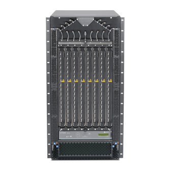
QFX3000-G QFabric System Deployment Guide Table 55 on page 158 lists the parts and their quantities in the packing list for a QFX3008-I Interconnect device. Table 55: Parts List for QFX3008-I Interconnect Device Configurations Component Quantity Chassis, including the midplane and rack-mounting brackets... -
Page 185: Installing Qfx3008-I Interconnect Device Mounting Hardware On Four-Post Racks Or Cabinets
Power cords 6 (single-phase wiring trays only) Related Unpacking a QFX3008-I Interconnect Device on page 156 Documentation QFX3008-I Interconnect Device Overview Installing QFX3008-I Interconnect Device Mounting Hardware on Four-Post Racks or Cabinets Supported Platforms QFX3000-G Copyright © 2015, Juniper Networks, Inc. -
Page 186: Installing Four-Post Mounting Shelf And Rear Support Bracket For Qfx3008-I Interconnect Device Four-Post Rack Or Cabinet Mounting
QFX3000-G QFabric System Deployment Guide Before you install the QFX3008-I Interconnect device in a four-post rack or cabinet, you must first install mounting hardware and remove the center-mounting brackets from the chassis. NOTE: In a rack, the device uses 21 U. You can mount two QFX3008-I Interconnect devices on a 42 U rack provided that the racks meet the strength requirements to support the combined weight of the devices. -
Page 187: Figure 23: Installing Four-Post Mounting Shelf And Rear Support Bracket For Qfx3008-I Interconnect Device Four-Post Rack Or Cabinet Mounting
Installing the Rear Support Bracket for QFX3008-I Interconnect Device Four-Post Rack or Cabinet Mounting on page 162 Installing the Four-Post Mounting Shelf for QFX3008-I Interconnect Device Four-Post Rack or Cabinet Mounting on page 162 Copyright © 2015, Juniper Networks, Inc. -
Page 188: Installing Cage Nuts For The Four-Post Mounting Shelf And Support Bracket For Qfx3008-I Interconnect Device Four-Post Rack Or Cabinet Mounting
QFX3000-G QFabric System Deployment Guide Installing Cage Nuts for the Four-Post Mounting Shelf and Support Bracket for QFX3008-I Interconnect Device Four-Post Rack or Cabinet Mounting For racks without threaded holes, you must install cage nuts on the rack or cabinet rails... -
Page 189: Installing Spacer Bars And Shelves For Qfx3008-I Interconnect Device Four-Post Rack Or Cabinet Mounting
“Installing Four-Post Mounting Shelf and Rear Support Bracket for QFX3008-I Interconnect Device Four-Post Rack or Cabinet Mounting” on page 160. Copyright © 2015, Juniper Networks, Inc. -
Page 190: Figure 24: Installing Spacer Bar And Shelves For Qfx3008-I Interconnect Device Four-Post Rack Or Cabinet Mounting
QFX3000-G QFabric System Deployment Guide Figure 24: Installing Spacer Bar and Shelves for QFX3008-I Interconnect Device Four-Post Rack or Cabinet Mounting For a four-post rack or cabinet, Table 60 on page 164 specifies the holes in which you insert mounting screws (an indicates a mounting hole location), and cage nuts if needed. -
Page 191: Installing Cage Nuts For Qfx3008-I Interconnect Device Four-Post Rack Or Cabinet Mounting
To install the small mounting shelf: On the back of each rear rack rail, partially insert a mounting screw into the lowest hole specified in Table 60 on page 164 for the small shelf. Copyright © 2015, Juniper Networks, Inc. -
Page 192: Installing The Large Mounting Shelf And Spacer Bars For Qfx3008-I Interconnect Device Four-Post Rack Or Cabinet Mounting
QFX3000-G QFabric System Deployment Guide Install the small shelf on the back rack rails. Rest the bottom slot of each ear on a mounting screw. The small shelf installs on the back of the rear rails, extending toward the center of the rack. The bottom of the small shelf should align with the bottom of the large shelf. -
Page 193: Racks
Interconnect devices on a 42 U rack provided that the racks meet the strength requirements to support the combined weight of the devices. If you are mounting two QFX3008-I Interconnect devices on a rack, mount the first device on the bottom of the rack. Copyright © 2015, Juniper Networks, Inc. -
Page 194: Figure 25: Installing The Mounting Hardware For A Two-Post Rack
QFX3000-G QFabric System Deployment Guide Figure 25: Installing the Mounting Hardware for a Two-Post Rack Open-frame rack Small mounting shelf Large mounting shelf For a two-post rack, Table 61 on page 168 specifies the holes in which you insert mounting screws (an indicates a mounting hole location), and cage nuts if needed. -
Page 195: Installing Cage Nuts For Qfx3008-I Interconnect Device Two-Post Rack
Table 61 on page 168 the large shelf. Installing the Small Mounting Shelf for QFX3008-I Interconnect Device Two-Post Rack Mounting To mount the chassis on a two-post rack, you must first install the mounting shelves on the rack. Copyright © 2015, Juniper Networks, Inc. -
Page 196: Installing The Large Mounting Shelf For Qfx3008-I Interconnect Device Two-Post Rack Mounting
QFX3000-G QFabric System Deployment Guide Before you begin, ensure that you have the following parts and tools available to install the small mounting shelf: A Phillips (+) screwdriver, number 2 or 3, depending on the size of your rack mounting... - Page 197 (not provided) Mounting screws appropriate for your rack (not provided) Rear support anchors to secure the chassis to the four-post mounting shelf and rear support bracket (provided) Copyright © 2015, Juniper Networks, Inc.
- Page 198 QFX3000-G QFabric System Deployment Guide NOTE: Earlier versions of the four-post rack mounting hardware did not require the rear support anchors. If your four-post rack mounting hardware includes spacer bars and two shelves the rear support anchors are not required.
-
Page 199: Figure 26: Installing A Qfx3008-I Interconnect Device In A Four-Post Rack
If your four-post rack mounting hardware includes spacer bars and two shelves the rear support anchors are not required. Secure the rear support anchors with the provided UNC 1/4-20 (right side) screws and M6 (left side) screws. Copyright © 2015, Juniper Networks, Inc. -
Page 200: Connecting Earth Ground To A Qfx3008-I Interconnect Device
QFX3000-G QFabric System Deployment Guide TIP: Because the rear support anchors are attached to the chassis grounding points, it is best to connect the chassis to earth ground while performing this step. See “Connecting Earth Ground to a QFX3008-I Interconnect Device” on page 174 for more information. - Page 201 Detach the ESD grounding strap from the site ESD grounding point. Attach an electrostatic discharge (ESD) grounding strap to your bare wrist, and connect the strap to the ESD point on the chassis. Copyright © 2015, Juniper Networks, Inc.
-
Page 202: Connecting Ac Power To A Qfx3008-I Interconnect Device With Single-Phase
QFX3000-G QFabric System Deployment Guide In a four-post rack, place the grounding lug attached to the grounding cable over one of the rear support anchors, as shown in Figure 28 on page 176. In a two-post rack, place the grounding cable lug over the grounding points on the bottom rear of the chassis below the wiring trays. - Page 203 Attach the ESD grounding strap to your bare wrist, and connect the strap to the ESD point on the chassis. Ensure that the wiring tray is fully inserted and latched securely in the chassis. See Installing a Wiring Tray in a QFX3008-I Interconnect Device. Copyright © 2015, Juniper Networks, Inc.
-
Page 204: Preparing Delta And Wye Three-Phase Power Cords
QFX3000-G QFabric System Deployment Guide Set the switch, which is near the top of the wiring tray faceplate, to the OFF (O) position. Locate the power cord or cords shipped with the device; the cords have plugs appropriate for your geographical location. -
Page 205: Figure 30: Assembling A Power Cord Using A 90° Connector
Figure 34 on page 181 shows the wiring tray being installed in the chassis, using the flat connector. Figure 30: Assembling a Power Cord Using a 90° Connector Figure 31: Assembling a Power Cord Using a Flat Connector Copyright © 2015, Juniper Networks, Inc. -
Page 206: Figure 32: Wye Wiring Tray With A 90° Connector Installed
QFX3000-G QFabric System Deployment Guide Figure 32: Wye Wiring Tray with a 90° Connector Installed Figure 33: Delta Wiring Tray with a Flat Connector Installed Copyright © 2015, Juniper Networks, Inc. -
Page 207: Figure 34: Installing A Three-Phase Wiring Tray With A Power Cord Installed
“AC Power Cord Specifications for a QFX3008-I Interconnect Device with Three-Phase Delta Wiring Trays” on page 135 “AC Power Cord Specifications for a QFX3008-I Interconnect Device with Three-Phase Wye Wiring Trays” on page 136. Copyright © 2015, Juniper Networks, Inc. - Page 208 QFX3000-G QFabric System Deployment Guide NOTE: Each wiring tray must be connected to a dedicated AC power source outlet. Before you begin to prepare the wiring trays for installation: Ensure that you understand how to prevent ESD damage. See Prevention of Electrostatic Discharge Damage.
-
Page 209: Connecting Ac Power To A Qfx3008-I Interconnect Device With Three-Phase
QFX3008-I Interconnect device to connect to earth ground. For instructions on connecting a QFX3008-I Interconnect device to ground using a separate grounding conductor, see “Connecting Earth Ground to a QFX3008-I Interconnect Device” on page 174. Copyright © 2015, Juniper Networks, Inc. - Page 210 QFX3000-G QFabric System Deployment Guide A QFX3008-I Interconnect device receives additional grounding when you plug the power supply in the device into a grounded AC power outlet by using the AC power cord appropriate for your geographical location. See “AC Power Cord Specifications for a QFX3008-I Interconnect Device with Three-Phase Delta Wiring Trays”...
- Page 211 Using a number 1 Phillips (+) screwdriver, loosen the four screws on the metal AC wiring compartment on the side of the wiring tray (see Figure 35 on page 186). Open the metal door of the wiring tray compartment. Copyright © 2015, Juniper Networks, Inc.
-
Page 212: Figure 35: Connecting Power To A Three-Phase Delta Ac Power Supply
QFX3000-G QFabric System Deployment Guide Connect the wires to the AC terminal block on the three-phase delta wiring tray (Figure 35 on page 186). Use a 1/4-in. slotted screwdriver to loosen the input terminal or grounding point screw, insert each wire into the grounding point or input terminal, and tighten the screw to between 23 in-lb (2.6 Nm) and 25 in-lb (2.8 Nm). -
Page 213: Connecting Ac Power To A Qfx3008-I Interconnect Device With Three-Phase
Each wiring tray must be connected to a dedicated AC power source outlet. Before you begin to connect power to the device: Ensure that you understand how to prevent ESD damage. See Prevention of Electrostatic Discharge Damage. Copyright © 2015, Juniper Networks, Inc. - Page 214 QFX3000-G QFabric System Deployment Guide Ensure that a licensed electrician has prepared the power cords. See “Preparing Delta and Wye Three-Phase Power Cords” on page 178. Ensure that you have the following parts and tools available to connect power to the...
-
Page 215: Figure 36: Connecting Power To The Three-Phase Wye Wiring Tray
Insert the wire labeled into the input terminal Figure 36: Connecting Power to the Three-Phase Wye Wiring Tray NOTE: The color of each AC power wire might vary. Verify that the power cable connections are correct. Copyright © 2015, Juniper Networks, Inc. -
Page 216: Connecting A Qfx Series Device To A Management Console
QFX3000-G QFabric System Deployment Guide Replace the cover on the wiring compartment, and using a number 1 Phillips (+) screwdriver, tighten the four screws. Repeat Step through Step for the other wiring tray. Related Powering On a QFX3008-I Interconnect Device on page 191... -
Page 217: Powering On A Qfx3008-I Interconnect Device
Installing an AC Power Supply in a QFX3008-I Interconnect Device Documentation Connecting AC Power to a QFX3008-I Interconnect Device with Single-Phase Wiring Trays on page 176 Connecting AC Power to a QFX3008-I Interconnect Device with Three-Phase Delta Wiring Trays on page 183 Copyright © 2015, Juniper Networks, Inc. - Page 218 QFX3000-G QFabric System Deployment Guide Connecting AC Power to a QFX3008-I Interconnect Device with Three-Phase Wye Wiring Trays on page 187 Powering Off a QFX3008-I Interconnect Device Copyright © 2015, Juniper Networks, Inc.
-
Page 219: Installing A Qfx3600 Node Device
Connecting AC Power to a QFX3500, QFX3600, or QFX3600-I Device on page 203 Connecting DC Power to a QFX3500, QFX3600, or QFX3600-I Device on page 205 Depending on how you will be using the QFX3600 or QFX3600-I device, take one of the following actions: Copyright © 2015, Juniper Networks, Inc. -
Page 220: Unpacking A Qfx3600 Or Qfx3600-I Device
QFX3000-G QFabric System Deployment Guide If you are using the QFX3600 device as a Node device in a QFX3000-G QFabric system, see “QFX3000-G QFabric System Installation Overview” on page 83 information about the steps to install and configure your QFX3000-G QFabric system. -
Page 221: Cabinet
The holes in the mounting brackets are placed at 1 U (1.75 in., or 4.45 cm.) apart so that the device can be mounted in any rack that provides holes spaced at that distance. Before mounting a QFX3600 or QFX3600-I device on two posts in a rack: Copyright © 2015, Juniper Networks, Inc. - Page 222 QFX3000-G QFabric System Deployment Guide Ensure you understand how to prevent electrostatic discharge (ESD) damage. See Prevention of Electrostatic Discharge Damage. Verify that the site meets the requirements described in Site Preparation Checklist for a QFX3600 or QFX3600-I Device. Place the rack in its permanent location, allowing adequate clearance for airflow and maintenance, and secure it to the building structure.
-
Page 223: Figure 39: Attaching The Front Or Rear Mounting Brackets To The Side Panel Of
Figure 39: Attaching the Front or Rear Mounting Brackets to the Side Panel of the Device Figure 40: Mounting the Device on Two Posts in a Rack Copyright © 2015, Juniper Networks, Inc. -
Page 224: Mounting A Qfx3600 Or Qfx3600-I Device On Four Posts In A Rack Or Cabinet
QFX3000-G QFabric System Deployment Guide Related Rack-Mounting and Cabinet-Mounting Warnings Documentation Connecting Earth Ground to QFX3600 or QFX3600-I Devices on page 201 Connecting AC Power to a QFX3500, QFX3600, or QFX3600-I Device on page 203 Connecting DC Power to a QFX3500, QFX3600, or QFX3600-I Device on page 205... - Page 225 With two mounting screws—and cage nuts and washers if your rack requires them—attach the second rear installation blade to the right rear of the rack at the point where you want to mount the device. Tighten the screws. Copyright © 2015, Juniper Networks, Inc.
-
Page 226: Figure 41: Attaching The Installation Blades To The Rear Of The Rack
QFX3000-G QFabric System Deployment Guide Figure 41: Attaching the Installation Blades to the Rear of the Rack Prepare the device for mounting. a. Place the device on a flat, stable surface. b. Align the mounting brackets along the front or rear of the side panels of the device chassis depending on how you want to mount the device. -
Page 227: Connecting Earth Ground To Qfx3600 Or Qfx3600-I Devices
Connecting DC Power to a QFX3500, QFX3600, or QFX3600-I Device on page 205 Configuring a QFX3600 Device as a Standalone Switch Connecting Earth Ground to QFX3600 or QFX3600-I Devices Supported Platforms QFabric System QFX3600 Copyright © 2015, Juniper Networks, Inc. - Page 228 QFX3000-G QFabric System Deployment Guide To meet safety and electromagnetic interference (EMI) requirements and to ensure proper operation, you must connect the QFX3600 and QFX3600-I devices to earth ground before you connect it to power. For installations that require a separate grounding conductor to the chassis, use the...
-
Page 229: Connecting Ac Power To A Qfx3500, Qfx3600, Or Qfx3600-I Device
201. The device gains additional grounding when you plug the power supply in the device into a grounded AC power outlet by using the AC power cord appropriate for your geographical location (see “AC Copyright © 2015, Juniper Networks, Inc. -
Page 230: Figure 44: Connecting An Ac Power Cord To An Ac Power Supply In A Qfx3500
QFX3000-G QFabric System Deployment Guide Power Cord Specifications for a QFX3500, QFX3600, or QFX3600-I Device” on page 139). Install the power supply in the chassis. For instructions on installing a power supply in a QFX3500 device, see Installing a Power Supply in a QFX3500 Device. For instructions on installing a power supply in a QFX3600 or QFX3600-I device, see Installing a Power Supply in a QFX3600 or QFX3600-I Device. -
Page 231: Connecting Dc Power To A Qfx3500, Qfx3600, Or Qfx3600-I Device
(FRU). You can remove and replace it without powering off the device or disrupting device functions. WARNING: DC-powered QFX3500, QFX3600 and QFX3600-I devices are intended for installation only in a restricted access location. Copyright © 2015, Juniper Networks, Inc. - Page 232 QFX3000-G QFabric System Deployment Guide NOTE: The battery returns of the DC power supply should be connected as an isolated DC return (DC-I). Before you begin connecting DC power to the device: Ensure that you have taken the necessary precautions to prevent electrostatic discharge (ESD) damage (see Prevention of Electrostatic Discharge Damage).
- Page 233 Do not connect the terminals to different sources. For example, connect –48 V from DC source feed A to the input terminals of one power supply and connect –48 V from feed B to the input terminals of the second Copyright © 2015, Juniper Networks, Inc.
-
Page 234: Figure 46: Dc Power Supply Faceplate For A Qfx3500, Qfx3600 Or Qfx3600-I
QFX3000-G QFabric System Deployment Guide power supply on the other side of the chassis. This configuration provides the commonly deployed A/B feed redundancy for the system. Secure the ring lug of the positive (+) DC power source cable to the V+ terminal on the DC power supply. -
Page 235: Connecting A Qfx Series Device To A Management Console
To connect the QFX Series to a management console (see Figure 21 on page 151 Figure 22 on page 151): Connect one end of the Ethernet cable to the console port (labeled CONSOLE Copyright © 2015, Juniper Networks, Inc. -
Page 236: Figure 48: Connecting The Qfx Series To A Management Console Through A
QFX3000-G QFabric System Deployment Guide Connect the other end of the Ethernet cable into the console server (see Figure 21 on page 151) or management console (see Figure 22 on page 151). Figure 48: Connecting the QFX Series to a Management Console Through... -
Page 237: Installing A Qfx3500 Node Device
If you are using the QFX3500 device as a standalone switch, follow the instructions in Configuring a QFX3500 Device as a Standalone Switch. If you are using the QFX3500 device as a Node device in a QFX3000-G QFabric system, see “QFX3000-G QFabric System Installation Overview”... -
Page 238: Unpacking A Qfx3500 Device
QFX3000-G QFabric System Deployment Guide Related Rack Requirements for a QFX3500 Device Documentation Cabinet Requirements for a QFX3500 Device Clearance Requirements for Airflow and Hardware Maintenance for a QFX3500 Device Unpacking a QFX3500 Device Supported Platforms QFabric System QFX3500 The QFX3500 device chassis is a rigid sheet-metal structure that houses the hardware components. -
Page 239: Mounting A Qfx3500 Device In A Rack Or Cabinet
Ensure that you have the following parts and tools available to mount the device on four posts in a rack: ESD grounding strap (provided). One pair of rear installation blades. These installation blades support the rear of the chassis, and must be installed (provided). Copyright © 2015, Juniper Networks, Inc. -
Page 240: Figure 50: Installing An Installation Blade In A Rack
QFX3000-G QFabric System Deployment Guide Eight screws to secure the chassis and rear installation blades to the rack (not provided). Appropriate screwdriver for the mounting screws (not provided). WARNING: The QFX3500 device must be supported at all four corners. Mounting the chassis using only the front brackets will damage the chassis and can result in serious bodily injury. -
Page 241: Connecting Earth Ground To A Qfx3500 Device
Documentation Connecting AC Power to a QFX3500, QFX3600, or QFX3600-I Device on page 203 Configuring a QFX3500 Device as a Standalone Switch Connecting Earth Ground to a QFX3500 Device Supported Platforms QFabric System QFX3500 Copyright © 2015, Juniper Networks, Inc. - Page 242 QFX3000-G QFabric System Deployment Guide To meet safety and electromagnetic interference (EMI) requirements and to ensure proper operation, you must connect the QFX3500 device to earth ground before you connect it to power. For installations that require a separate grounding conductor to the chassis, you must...
-
Page 243: Connecting Ac Power To A Qfx3500, Qfx3600, Or Qfx3600-I Device
Before you begin connecting AC power to the device: Ensure that you have taken the necessary precautions to prevent electrostatic discharge (ESD) damage (see Prevention of Electrostatic Discharge Damage). Ensure that you have connected the device chassis to earth ground. Copyright © 2015, Juniper Networks, Inc. - Page 244 QFX3000-G QFabric System Deployment Guide CAUTION: Before you connect power to the device, a licensed electrician must attach a cable lug to the grounding and power cables that you supply. A cable with an incorrectly attached lug can damage the device (for example, by causing a short circuit).
-
Page 245: Figure 53: Connecting An Ac Power Cord To An Ac Power Supply In A Qfx3500
Replace a failed power supply with a blank panel or new power supply within 1 minute of removal to prevent chassis overheating. Related AC Power Supply for a QFX3500, QFX3600, or QFX3600-I Device Documentation AC Power Supply LEDs on a QFX3500, QFX3600, or QFX3600-I Device Copyright © 2015, Juniper Networks, Inc. -
Page 246: Connecting Dc Power To A Qfx3500, Qfx3600, Or Qfx3600-I Device
QFX3000-G QFabric System Deployment Guide Connecting DC Power to a QFX3500, QFX3600, or QFX3600-I Device Supported Platforms QFabric System QFX3500, QFX3600 The power supply in QFX3500, QFX3600, and QFX3600-I devices is a hot-removable and hot-insertable field-replaceable unit (FRU). You can remove and replace it without powering off the device or disrupting device functions. - Page 247 Connect each power supply to the power sources. Secure power source cables to the power supplies by screwing the ring lugs attached to the cables to the appropriate terminals by using the screw from the terminals (see Figure 47 on page 209 Figure 46 on page 208). Copyright © 2015, Juniper Networks, Inc.
-
Page 248: Figure 55: Dc Power Supply Faceplate For A Qfx3500, Qfx3600 Or Qfx3600-I
QFX3000-G QFabric System Deployment Guide CAUTION: The DC power supply has four terminals labeled V+, V+, V–, and V– for connecting DC power source cables labeled positive (+) and negative (–). The V+ terminals are shunted internally together, as are the V- terminals. -
Page 249: Connecting A Qfx Series Device To A Management Console
PC directly to the QFX Series, use a combination of the RJ-45 cable and RJ-45 to DB-9 adapter supplied with the device and a USB to DB-9 male adapter. You must provide the USB to DB-9 male adapter. Copyright © 2015, Juniper Networks, Inc. -
Page 250: Figure 57: Connecting The Qfx Series To A Management Console Through A
QFX3000-G QFabric System Deployment Guide To connect the QFX Series to a management console (see Figure 21 on page 151 Figure 22 on page 151): Connect one end of the Ethernet cable to the console port (labeled CONSOLE Connect the other end of the Ethernet cable into the console server (see... -
Page 251: System
Supported Platforms QFX3000-G A QFX3000-G QFabric system control plane and management network is formed by connecting the QFX Series devices in your network to two Virtual Chassis. If you are creating a copper-based control plane network, you use four EX4200-48T Ethernet switches in each Virtual Chassis. -
Page 252: Figure 59: Qfx3000-G Qfabric System Copper-Based Control Plane-Inter-Virtual Chassis Lag Connections
Before you begin to interconnect two Virtual Chassis for QFX3000-G QFabric system control plane redundancy: Install your QFabric system hardware (Director group, Interconnect devices, and Node devices). See “Installing and Connecting a QFX3100 Director Device” on page 143, “Installing and Connecting a QFX3008-I Interconnect Device”... -
Page 253: Figure 60: Connecting A Fiber-Optic Cable To An Optical Transceiver Installed In An Ex Series Switch
Chapter 13: Cabling a Copper-Based Control Plane for the QFX3000-G QFabric System Table 64: Virtual Chassis-to-Virtual Chassis Copper-Based Control Plane Port Assignments Member 0 Member 1 Member 2 Member 3 Connect Connect Connect Connect xe-0/1/0 xe-0/1/0 xe-1/1/0 xe-1/1/0 xe-2/1/0 xe-2/1/0... -
Page 254: Connecting Qfx3100 Director Devices In A Director Group
Figure 61 on page 228 through Figure 63 on page 229). Figure 61: QFX3100 Director Group Control Plane Connections for QFX3000-G QFabric System Using Copper-Based Control Plane 0 1 2 3 0 1 2 3 Patch cables between Director devices 0 1 2 3... -
Page 255: Figure 62: Qfx3100 Director Group Control Plane Connections For Qfx3000-Gqfabric System Using Fiber-Based Control Plane
Chapter 13: Cabling a Copper-Based Control Plane for the QFX3000-G QFabric System Figure 62: QFX3100 Director Group Control Plane Connections for QFX3000-G QFabric System Using Fiber-Based Control Plane 0 1 2 3 0 1 2 3 Patch cables between Director devices... - Page 256 (labeled ) on the second network module on the second Director device. Related Connecting QFX3100 Director Devices to a Copper-Based QFX3000-G QFabric System Documentation Control Plane Network on page 231 Copyright © 2015, Juniper Networks, Inc.
-
Page 257: Connecting Qfx3100 Director Devices To A Copper-Based Qfx3000-G Qfabric System Control Plane Network
Chapter 13: Cabling a Copper-Based Control Plane for the QFX3000-G QFabric System Connecting QFX3100 Director Devices to a Fiber-Based QFX3000-G QFabric System Control Plane Network on page 251 Connecting QFX3100 Director Devices to a Copper-Based QFX3000-M QFabric System Control Plane Network... - Page 258 “Cable Specifications for Copper-Based Control Plane Connections for the QFabric System” on page 126. To connect a QFX3100 Director device to the QFX3000-G QFabric control plane network (see Figure 64 on page 231): Connect both network modules on the first Director device (labeled...
-
Page 259: Management
Chapter 13: Cabling a Copper-Based Control Plane for the QFX3000-G QFabric System Table 65: QFX3100 Director Device-to-Virtual Chassis Control Plane Port Assignments for DG0 Network Module Port Network Module Port Network Module Port Network Module Port 3 Virtual Chassis port... -
Page 260: Connecting A Qfx3008-I Interconnect Device To A Copper-Based Qfx3000-Gqfabric System Control Plane Network
Supported Platforms QFX3000-G A QFX3000-G QFabric system control plane and management network is formed by connecting the QFabric system devices in your network to two Virtual Chassis composed of four EX4200 switches each. QFX3008-I Interconnect Devices have four small form factor pluggable plus (SFP+) management ports on each Control Board. -
Page 261: Figure 65: Qfx3008-I Interconnect Device Control Plane Connections
Chapter 13: Cabling a Copper-Based Control Plane for the QFX3000-G QFabric System Figure 65: QFX3008-I Interconnect Device Control Plane Connections Port 0 Port 1 Port 0 Port 1 Port 0 Port 1 Port 0 Port 1 ge-0/0/39 ge-0/0/39 ge-1/0/39 ge-1/0/39... -
Page 262: Table 67: Interconnect Device Port Mappings
Interconnect the two Virtual Chassis switches using the 10-Gigabit Ethernet SFP+ uplink ports. For more information, see “Interconnecting Two Virtual Chassis for Copper-Based QFX3000-G QFabric System Control Plane Redundancy” on page 225. Ensure that 1000BASE-T SFP transceivers are installed in port... - Page 263 Chapter 13: Cabling a Copper-Based Control Plane for the QFX3000-G QFabric System To connect each QFX3008-I Interconnect Device to the QFX3000-G QFabric system control plane network (see Figure 65 on page 235: Connect the first Interconnect device. Connect one end of the first RJ-45 patch cable to the first SFP management port...
-
Page 264: Connecting A Qfx3600 Node Device To A Copper-Based Qfx3000-G Qfabric System Control Plane Network
Connecting a QFX3600 Node Device to a Copper-Based QFX3000-G QFabric System Control Plane Network Supported Platforms QFX3000-G A QFX3000-G QFabric system control plane and management network is formed by connecting the QFX series devices in your network to two Virtual Chassis composed of Copyright © 2015, Juniper Networks, Inc. -
Page 265: Figure 66: Qfx3600 Node Device Control Plane Connections
Figure 66: QFX3600 Node Device Control Plane Connections Node ge-0/0/0 ge-0/0/0 Before you begin to cable the QFX3000-G QFabric system control plane and management network: Install your QFabric system hardware (Director group, Interconnect devices, and Node devices). For more information, see “Installing and Connecting a QFX3100 Director... -
Page 266: Table 68: Qfx3600 Node Device-To-Virtual Chassis Control Plane Port
Node 127: ge-0/0/31 ge-1/0/31 ge-2/0/31 ge-3/0/31 To connect a QFX3600 Node device to the QFX3000-G QFabric system control plane network (see Figure 66 on page 239): Connect one end of the first RJ-45 patch cable to the first management port (labeled ) on the Node device front panel. -
Page 267: Connecting A Qfx3500 Node Device To A Copper-Based Qfx3000-G Qfabric System Control Plane Network
RJ-45 1-Gbps management ports labeled EX4200-48T switches with an SFP+ uplink module installed. Before you begin to connect a QFX3500 Node device to the QFX3000-G QFabric system control plane network: Copyright © 2015, Juniper Networks, Inc. -
Page 268: Table 69: Qfx3500 Node Device-To-Virtual Chassis Copper-Based Control Plane Port Assignments
Interconnect the two Virtual Chassis switches using the 10-Gigabit Ethernet SFP+ uplink ports. For more information, see “Interconnecting Two Virtual Chassis for Copper-Based QFX3000-G QFabric System Control Plane Redundancy” on page 225. Ensure that you have two RJ-45 patch cables available. For cable specifications, see “Cable Specifications for Copper-Based Control Plane Connections for the QFabric... - Page 269 Chapter 13: Cabling a Copper-Based Control Plane for the QFX3000-G QFabric System To connect a QFX3500 Node device to the QFX3000-G QFabric system control plane network (see Figure 67 on page 241): Connect one end of the first RJ-45 patch cable to the first management port (labeled ) on the Node device management board.
- Page 270 QFX3000-G QFabric System Deployment Guide Copyright © 2015, Juniper Networks, Inc.
-
Page 271: System
Supported Platforms QFX3000-G A QFX3000-G QFabric system control plane and management network is formed by connecting the QFX Series devices in your network to two Virtual Chassis. If you are creating a fiber-based control plane network, you use eight EX4200-24F Ethernet switches in each Virtual Chassis. -
Page 272: Figure 68: Qfx3000-G Qfabric System Fiber-Based Control Plane-Inter-Virtual Chassis Lag Connections
Before you begin to interconnect two Virtual Chassis for QFX3000-G QFabric system control plane redundancy: Install your QFabric system hardware (Director group, Interconnect devices, and Node devices). See “Installing and Connecting a QFX3100 Director Device” on page 143, “Installing and Connecting a QFX3008-I Interconnect Device”... -
Page 273: Figure 69: Connecting A Fiber-Optic Cable To An Optical Transceiver Installed In An Ex Series Switch
Chapter 14: Cabling a Fiber-Based Control Plane for the QFX3000-G QFabric System Virtual Chassis to connect to each of the QFabric system device types. Such design simplifies installation and facilitates timely deployment of a QFabric system. It also permits the use of a standard Virtual Chassis configuration (see “Example: Configuring... -
Page 274: Connecting Qfx3100 Director Devices In A Director Group
Figure 61 on page 228 through Figure 63 on page 229). Figure 70: QFX3100 Director Group Control Plane Connections for QFX3000-G QFabric System Using Copper-Based Control Plane 0 1 2 3 0 1 2 3 Patch cables between Director devices 0 1 2 3... -
Page 275: Figure 71: Qfx3100 Director Group Control Plane Connections For Qfx3000-Gqfabric System Using Fiber-Based Control Plane
Chapter 14: Cabling a Fiber-Based Control Plane for the QFX3000-G QFabric System Figure 71: QFX3100 Director Group Control Plane Connections for QFX3000-G QFabric System Using Fiber-Based Control Plane 0 1 2 3 0 1 2 3 Patch cables between Director devices... - Page 276 (labeled ) on the second network module on the second Director device. Related Connecting QFX3100 Director Devices to a Copper-Based QFX3000-G QFabric System Documentation Control Plane Network on page 231 Copyright © 2015, Juniper Networks, Inc.
-
Page 277: Connecting Qfx3100 Director Devices To A Fiber-Based Qfx3000-G Qfabric System Control Plane Network
Chapter 14: Cabling a Fiber-Based Control Plane for the QFX3000-G QFabric System Connecting QFX3100 Director Devices to a Fiber-Based QFX3000-G QFabric System Control Plane Network on page 251 Connecting QFX3100 Director Devices to a Copper-Based QFX3000-M QFabric System Control Plane Network... -
Page 278: Figure 73: Qfx3100 Director Group To Virtual Chassis Connections For
Series device types. Such design simplifies installation and facilitates timely deployment of a QFabric system. It also permits the use of a standard Virtual Chassis configuration (see “Example: Configuring a Fiber-Based Control Plane for the QFX3000-G QFabric System” on page 327). - Page 279 Chapter 14: Cabling a Fiber-Based Control Plane for the QFX3000-G QFabric System Install your QFabric system hardware (Director group, Interconnect devices, and Node devices). See “Installing and Connecting a QFX3100 Director Device” on page 143, “Installing and Connecting a QFX3008-I Interconnect Device” on page 155, “Installing...
-
Page 280: Management
QFX3000-G QFabric System Deployment Guide on the second network module (also labeled through ) to the second Virtual Chassis ). The ports used are the same on each Virtual Chassis. Table 71: QFX3100 Director Device-to-VIrtual Chassis Control Plane Port Assignments for DG0... -
Page 281: Connecting A Qfx3008-I Interconnect Device To A Fiber-Based Qfx3000-Gqfabric System Control Plane Network
Chapter 14: Cabling a Fiber-Based Control Plane for the QFX3000-G QFabric System To connect a QFX3100 Director device to a network for out-of-band management: Connect one end of the Ethernet cable to the management port (labeled MGMT the Director device front panel). -
Page 282: Figure 74: Qfx3000-G Qfabric System Fiber-Based Control Plane-Interconnect Device To Virtual Chassis Connections
QFabric system. It also enables the use of a standard Virtual Chassis configuration (see “Example: Configuring a Fiber-Based Control Plane for the QFX3000-G QFabric System” on page 327). Before you begin to connect a QFX3008-I Interconnect Device to the fiber-based QFX3000-G QFabric system control plane network: Copyright ©... -
Page 283: Table 73: Interconnect Device Port Mappings
Chapter 14: Cabling a Fiber-Based Control Plane for the QFX3000-G QFabric System Install your QFabric system hardware (Director group, Interconnect devices, and Node devices). For more information, see “Installing and Connecting a QFX3100 Director Device” on page 143, “Installing and Connecting a QFX3008-I Interconnect Device” on... - Page 284 QFX3000-G QFabric System Deployment Guide Table 73: Interconnect Device Port Mappings (continued) Interconnect Device Virtual Chassis VC0 Virtual Chassis VC1 CB0, port 0 ge-0/0/18 CB0, port 1 ge-0/0/18 CB1, port 0 ge-1/0/18 CB1, port 1 ge-1/0/18 CB0, port 0 ge-2/0/18...
- Page 285 Chapter 14: Cabling a Fiber-Based Control Plane for the QFX3000-G QFabric System To connect each QFX3600-I Interconnect device to the fiber-based control plane network: WARNING: Do not look directly into a fiber-optic transceiver or into the ends of fiber-optic cables. Fiber-optic transceivers and fiber-optic cables connected to transceivers emit laser light that can damage your eyes.
- Page 286 QFX3000-G QFabric System Deployment Guide CB 1 Connect the other end of that cable to port on the first Virtual Chassis. ge-3/0/19 Connect one end of the fourth fiber optic cable to the SFP optical transceiver in the second management port (labeled...
-
Page 287: Connecting A Qfx3600 Node Device To A Fiber-Based Qfx3000-G Qfabric System Control Plane Network
Chapter 14: Cabling a Fiber-Based Control Plane for the QFX3000-G QFabric System Connect the other end of that cable to port on the second Virtual Chassis. ge-3/0/18 Related Connecting a QFX3600 Node Device to a QFX3008-I Interconnect Device on page 269... - Page 288 QFX3000-G QFabric System Deployment Guide Before you begin to connect a QFX3600 Node device to the fiber-based QFX3000-G QFabric system control plane network: Install your QFabric system hardware (Director group, Interconnect devices, and Node devices). For more information, see “Installing and Connecting a QFX3100 Director Device”...
-
Page 289: Table 74: Qfx3600 Node Device-To-Virtual Chassis Fiber-Based Control Plane Port Assignments
Chapter 14: Cabling a Fiber-Based Control Plane for the QFX3000-G QFabric System Table 74: QFX3600 Node Device-to-Virtual Chassis Fiber-Based Control Plane Port Assignments Member 0 Member 1 Member 2 Member 3 Member 4 Member 5 Member 6 Member 7 Node: 0... -
Page 290: Connecting A Qfx3500 Node Device To A Fiber-Based Qfx3000-G Qfabric System Control Plane Network
Supported Platforms QFX3000-G A QFX3000-G QFabric system control plane and management network is formed by connecting the QFX Series devices in your network to two Virtual Chassis composed of EX4200 switches. If you are creating a fiber-based control plane network, you use eight EX4200-24F Ethernet switches in each Virtual Chassis. -
Page 291: Figure 76: Qfx3500 Node Device Fiber-Based Control Plane Connections For
Chapter 14: Cabling a Fiber-Based Control Plane for the QFX3000-G QFabric System Figure 76: QFX3500 Node Device Fiber-Based Control Plane Connections for QFX3000-M QFabric System ge-0/0/0 ge-0/0/0 Use the following QFX3500 Node devices and EX4200 switches for a fiber-based QFX3000-G QFabric system control plane network: QFX3500 Node devices with an SFP management board installed. -
Page 292: Table 75: Qfx3500 Node Device-To-Virtual Chassis Fiber-Based Control Plane
QFX3000-G QFabric System Deployment Guide Ensure that you have installed 1-Gigabit Ethernet SFP transceivers in management ports on each QFX3500 Node device (see Installing a Transceiver in a QFX Series Device). For a list of supported transceivers and required cables, see “Interface... - Page 293 Chapter 14: Cabling a Fiber-Based Control Plane for the QFX3000-G QFabric System To connect a QFX3500 Node device to the fiber-based QFX3000-G QFabric system control plane network (see Figure 76 on page 265): WARNING: Do not look directly into a fiber-optic transceiver or into the ends of fiber-optic cables.
- Page 294 QFX3000-G QFabric System Deployment Guide Copyright © 2015, Juniper Networks, Inc.
-
Page 295: Cabling The Data Plane For The Qfx3000-G Qfabric System
Connecting a QFX3600 Node Device to a QFX3008-I Interconnect Device Supported Platforms QFX3000-G To form the data plane in a QFX3000-G QFabric system, you connect the QSFP+ uplink ports (labeled through ) on the QFX3600 Node device to the QSFP+ ports on the 16-port QSFP+ front cards in a QFX3008-I Interconnect device. - Page 296 QFX3000-G QFabric System Deployment Guide Review “Interface Specifications for SFP, SFP+, and QSFP+ Transceivers for the QFX Series” on page 104 for information about the optical interface characteristics. Ensure that you have taken the necessary precautions for safe handling of lasers (see Laser and LED Safety Guidelines and Warnings for the QFX Series).
-
Page 297: Connecting A Qfx3500 Node Device To A Qfx3008-I Interconnect Device
Connecting a QFX3500 Node Device to a QFX3008-I Interconnect Device Supported Platforms QFX3000-G To form the data plane in a QFX3000-G QFabric system, you connect the QSFP+ uplink ports (labeled through ) on the QFX3500 Node device to the QSFP+ ports on the 16-port QSFP+ front cards in a QFX3008-I Interconnect device. - Page 298 QFX3000-G QFabric System Deployment Guide If the connector at the other end of the fiber-optic cable is covered by a rubber safety cap, remove the cap. Save the cap. Remove the rubber safety cap from the QSFP+ optical transceiver on the 16-port QSFP+ front card on the QFX3008-I Interconnect device.
-
Page 299: Configuration
PART 3 Configuration Initial Setup on page 275 QFabric System Configuration on page 369 QFabric System Licensing on page 407 Configuration Statements on page 415 Copyright © 2015, Juniper Networks, Inc. - Page 300 QFX3000-G QFabric System Deployment Guide Copyright © 2015, Juniper Networks, Inc.
-
Page 301: Initial Setup
QFabric System Initial and Default Configuration Information on page 275 Converting the Device Mode for a QFabric System Component on page 277 Example: Configuring the Virtual Chassis for the QFX3000-G QFabric System Control Plane on page 283 Example: Configuring a Fiber-Based Control Plane for the QFX3000-G QFabric... - Page 302 Set an IP address for the default partition. Add the software serial number for your QFabric system. (Review the e-mail containing the software serial number that you received from Juniper Networks when you purchased your QFabric system.) Set the starting MAC address and the range of MAC addresses for the QFabric system.
-
Page 303: Converting The Device Mode For A Qfabric System Component
QFX3000-M QFabric System Installation Overview Converting the Device Mode for a QFabric System Component on page 277 Example: Configuring the Virtual Chassis for the QFX3000-G QFabric System Control Plane on page 283 Example: Configuring EX4200 Switches for the Copper-Based QFX3000-M QFabric... -
Page 304: Table 76: Support For Device Mode Options
QFX3000-G QFabric System Deployment Guide You can configure some devices to act as a standalone switch or participate in a QFabric system in a particular role. To change the role of your device, you must set the device mode. Table 76 on page 278 shows the device modes available for various devices. - Page 305 (Optional) If you change the device back from Node device mode to standalone mode, restore the saved backup configuration from your external location. Copyright © 2015, Juniper Networks, Inc.
- Page 306 QFX3000-G QFabric System Deployment Guide root@switch# load configuration-name external-path Node Device to Interconnect Device To convert your device from Node device mode to Interconnect device mode, follow these steps: From the default partition CLI prompt, back up your QFabric system configuration to an external location.
- Page 307 QFabric system, and reconfigure any aliases for the device at the QFabric default partition CLI prompt. QFabric Component (Interconnect or Node Device) to Standalone Switch Copyright © 2015, Juniper Networks, Inc.
- Page 308 QFX3000-G QFabric System Deployment Guide To convert your QFabric component from either Interconnect device mode or Node device mode to standalone switch mode, follow these steps: From the default partition CLI prompt, back up your QFabric system configuration to an external location.
-
Page 309: Control Plane
QFabric System This example shows you how to connect QFabric system components and configure the Virtual Chassis used by the QFX3000-G QFabric system control plane network. Proper wiring of Director devices, Interconnect devices, and Node devices to the Virtual Chassis, combined with a standard configuration, enables you to bring up the internal QFabric system management network and prepare your QFabric system for full operation. - Page 310 EX4200, EX4500, or EX4550 Virtual Chassis (CLI Procedure). Overview The QFX3000-G QFabric system control plane network connects the Director group, Interconnect devices, and Node devices in a QFabric system across a pair of redundant Virtual Chassis. By separating the management control plane from the data plane, the QFabric system can scale efficiently.
-
Page 311: Table 77: Qfx3000-G Qfabric System Virtual Chassis Control Plane Port
Table 77 on page 285 shows the specific mappings of QFabric system control plane network ports from the Virtual Chassis to the QFabric system components. Table 77: QFX3000-G QFabric System Virtual Chassis Control Plane Port Assignments Member Port QFabric System... - Page 312 QFX3000-G QFabric System Deployment Guide Table 77: QFX3000-G QFabric System Virtual Chassis Control Plane Port Assignments (continued) Member Port QFabric System Member 0 Member 1 Member 2 Member 3 Number Component Node1 Node33 Node65 Node97 ge-X/0/1 Node devices ge-0/0/1 ge-1/0/1...
- Page 313 Chapter 16: Initial Setup Table 77: QFX3000-G QFabric System Virtual Chassis Control Plane Port Assignments (continued) Member Port QFabric System Member 0 Member 1 Member 2 Member 3 Number Component Node14 Node46 Node78 Node110 ge-X/0/14 Node devices ge-0/0/14 ge-1/0/14 ge-2/0/14...
- Page 314 QFX3000-G QFabric System Deployment Guide Table 77: QFX3000-G QFabric System Virtual Chassis Control Plane Port Assignments (continued) Member Port QFabric System Member 0 Member 1 Member 2 Member 3 Number Component Node27 Node59 Node91 Node123 ge-X/0/27 Node devices ge-0/0/27 ge-1/0/27...
- Page 315 Chapter 16: Initial Setup Table 77: QFX3000-G QFabric System Virtual Chassis Control Plane Port Assignments (continued) Member Port QFabric System Member 0 Member 1 Member 2 Member 3 Number Component DG0 port 0 DG0 port 1 DG0 port 2 Reserved...
-
Page 316: Figure 78: Qfx3000-G Qfabric System Control Plane-Director Group To Virtual
QFX3000-G QFabric System Deployment Guide Figure 78: QFX3000-G QFabric System Control Plane—Director Group to Virtual Chassis Connections 0 1 2 3 0 1 2 3 Patch cables between Director devices 0 1 2 3 0 1 2 3 To port 40... -
Page 317: Table 79: Hardware To Software Port Mappings For Director Device Network
Virtual Chassis. In general, connect one port from each Control Board module in an Interconnect device to the first Virtual Chassis, and a second port from each Control Board module to the second Virtual Chassis. Copyright © 2015, Juniper Networks, Inc. -
Page 318: Figure 79: Qfx3000-G Qfabric System Control Plane-Interconnect Device To
QFX3000-G QFabric System Deployment Guide Figure 79: QFX3000-G QFabric System Control Plane—Interconnect Device to Virtual Chassis Connections Port 0 Port 1 Port 0 Port 1 Port 0 Port 1 Port 0 Port 1 ge-0/0/39 ge-0/0/39 ge-1/0/39 ge-1/0/39 ge-2/0/39 ge-2/0/39 ge-3/0/39... -
Page 319: Figure 80: Qfx3000-G Qfabric System Control Plane-Node Device To Virtual
Virtual Chassis. In general, connect the first management port from a Node device to the first Virtual Chassis, and the second management port to the second Virtual Chassis. Figure 80: QFX3000-G QFabric System Control Plane—Node Device to Virtual Chassis Connections ge-0/0/0... -
Page 320: Figure 81: Qfx3000-G Qfabric System Control Plane-Inter-Virtual Chassis
Virtual Chassis portion of the control plane. In general, connect each 10-Gigabit Ethernet uplink port from the first Virtual Chassis to the corresponding 10-Gigabit Ethernet uplink port on the second Virtual Chassis. Figure 81: QFX3000-G QFabric System Control Plane—Inter-Virtual Chassis LAG Connections xe-0/1/0... -
Page 321: Table 83: Virtual Chassis Lag Port Mappings
010 set groups qfabric class-of-service classifiers ieee-802.1 onep_qfabric_classifier forwarding-class class_0 loss-priority high code-points 001 set groups qfabric class-of-service classifiers inet-precedence IP_qfabric_classifier forwarding-class class_3 loss-priority low code-points 110 Copyright © 2015, Juniper Networks, Inc. - Page 322 QFX3000-G QFabric System Deployment Guide set groups qfabric class-of-service classifiers inet-precedence IP_qfabric_classifier forwarding-class class_3 loss-priority low code-points 111 set groups qfabric class-of-service classifiers inet-precedence IP_qfabric_classifier forwarding-class class_2 loss-priority low code-points 100 set groups qfabric class-of-service classifiers inet-precedence IP_qfabric_classifier forwarding-class class_2 loss-priority high code-points 101...
- Page 323 Director_Device_DG7_LAG_Interfaces description "QFabric Director Device - DG7" set interfaces interface-range Director_Device_DG7_LAG_Interfaces ether-options 802.3ad set interfaces interface-range Control_Plane_Inter_VC_LAG_Interfaces member "xe-[0-3]/1/0" set interfaces interface-range Control_Plane_Inter_VC_LAG_Interfaces member "xe-[0-3]/1/2" set interfaces interface-range Control_Plane_Inter_VC_LAG_Interfaces description "QFabric Control Plane (Inter-VC LAG)" Copyright © 2015, Juniper Networks, Inc.
- Page 324 QFX3000-G QFabric System Deployment Guide set interfaces interface-range Control_Plane_Inter_VC_LAG_Interfaces ether-options 802.3ad ae8 set interfaces ae0 apply-groups qfabric-int set interfaces ae0 apply-groups qfabric-ae set interfaces ae0 description "QFabric Director Device - DG0" set interfaces ae1 apply-groups qfabric-int set interfaces ae1 apply-groups qfabric-ae set interfaces ae1 description "QFabric Director Device - DG1"...
- Page 325 111 user@switch# set groups qfabric class-of-service classifiers ieee-802.1 onep_qfabric_classifier forwarding-class class_2 loss-priority low code-points 100 user@switch# set groups qfabric class-of-service classifiers ieee-802.1 onep_qfabric_classifier forwarding-class class_2 loss-priority high code-points Copyright © 2015, Juniper Networks, Inc.
- Page 326 QFX3000-G QFabric System Deployment Guide user@switch# set groups qfabric class-of-service classifiers ieee-802.1 onep_qfabric_classifier forwarding-class class_0 loss-priority low code-points user@switch# set groups qfabric class-of-service classifiers ieee-802.1 onep_qfabric_classifier forwarding-class class_0 loss-priority high code-points user@switch# set groups qfabric class-of-service classifiers inet-precedence IP_qfabric_classifier forwarding-class class_3 loss-priority low code-points 110...
- Page 327 Director_Device_DG1_LAG_Interfaces ether-options 802.3ad ae1 user@switch# set interfaces interface-range Director_Device_DG2_LAG_Interfaces member "ge-[0-3]/0/42" user@switch# set interfaces interface-range Director_Device_DG2_LAG_Interfaces description "QFabric Director Device - DG2" user@switch# set interfaces interface-range Director_Device_DG2_LAG_Interfaces ether-options 802.3ad ae2 Copyright © 2015, Juniper Networks, Inc.
- Page 328 QFX3000-G QFabric System Deployment Guide user@switch# set interfaces interface-range Director_Device_DG3_LAG_Interfaces member "ge-[0-3]/0/43" user@switch# set interfaces interface-range Director_Device_DG3_LAG_Interfaces description "QFabric Director Device - DG3" user@switch# set interfaces interface-range Director_Device_DG3_LAG_Interfaces ether-options 802.3ad ae3 user@switch# set interfaces interface-range Director_Device_DG4_LAG_Interfaces member "ge-[0-3]/0/44" user@switch# set interfaces interface-range Director_Device_DG4_LAG_Interfaces description "QFabric Director Device - DG4"...
- Page 329 The following configuration is the standard configuration that applies universally to both Virtual Chassis in your QFabric system control plane network. [edit] Copyright © 2015, Juniper Networks, Inc.
- Page 330 QFX3000-G QFabric System Deployment Guide groups { qfabric { system { commit { synchronize; chassis { redundancy { graceful-switchover; aggregated-devices { ethernet { device-count 10; alarm { management-ethernet { link-down ignore; fpc 0 { pic 1 { sfpplus { pic-mode 10g;...
- Page 331 001; inet-precedence IP_qfabric_classifier { forwarding-class class_3 { loss-priority low code-points [ 110 111 ]; forwarding-class class_2 { loss-priority low code-points 100; loss-priority high code-points 101; forwarding-class class_0 { loss-priority low code-points 010; Copyright © 2015, Juniper Networks, Inc.
- Page 332 QFX3000-G QFabric System Deployment Guide loss-priority high code-points 001; forwarding-classes { class class_3 queue-num 7; class class_2 queue-num 2; class class_0 queue-num 0; interfaces { ge-*/0/* { scheduler-map cpe_network_smap; unit 0 { classifiers { ieee-802.1 onep_qfabric_classifier; inet-precedence IP_qfabric_classifier; ae* { scheduler-map cpe_network_smap;...
- Page 333 Node_Device_Interfaces { member "ge-[0-3]/0/[0-31]"; description "QFabric Node Device"; apply-groups qfabric-int; interface-range Interconnect_Device_Interfaces { member "ge-[0-3]/0/[38-39]"; description "QFabric Interconnect Device"; apply-groups qfabric-int; interface-range Director_Device_DG0_LAG_Interfaces { member "ge-[0-3]/0/40"; description "QFabric Director Device - DG0"; ether-options { Copyright © 2015, Juniper Networks, Inc.
- Page 334 QFX3000-G QFabric System Deployment Guide 802.3ad ae0; interface-range Director_Device_DG1_LAG_Interfaces { member "ge-[0-3]/0/41"; description "QFabric Director Device - DG1"; ether-options { 802.3ad ae1; interface-range Director_Device_DG2_LAG_Interfaces { member "ge-[0-3]/0/42"; description "QFabric Director Device - DG2"; ether-options { 802.3ad ae2; interface-range Director_Device_DG3_LAG_Interfaces { member "ge-[0-3]/0/43";...
- Page 335 [ qfabric-int qfabric-ae ]; description "QFabric Director Device - DG7"; ae8 { description "QFabric Control Plane (Inter-VC LAG)"; mtu 9216; aggregated-ether-options { link-speed 10g; lacp { active; unit 0 { family ethernet-switching { vlan { members qfabric; Copyright © 2015, Juniper Networks, Inc.
- Page 336 QFX3000-G QFabric System Deployment Guide The following portion of the configuration applies to the specific requirements of your management network. Modify this section to meet the needs of your network. [edit] system { host-name qfabric-control-plane; services { ssh; telnet; web-management { http;...
- Page 337 Backup vcp-0 vcp-1 2 (FPC 2) Prsnt BP0210458724 ex4200-48t Linecard vcp-0 vcp-1 3 (FPC 3) Prsnt BP0210477189 ex4200-48t Linecard vcp-0 Member ID for next new member: 4 (FPC 4) {master:0} user@vc0> show interfaces terse Copyright © 2015, Juniper Networks, Inc.
- Page 338 QFX3000-G QFabric System Deployment Guide Interface Admin Link Proto Local Remote ge-0/0/0 ge-0/0/0.0 eth-switch ge-0/0/1 ge-0/0/1.0 eth-switch ge-0/0/2 ge-0/0/2.0 eth-switch ge-0/0/3 ge-0/0/3.0 eth-switch ge-0/0/4 ge-0/0/4.0 eth-switch ge-0/0/5 ge-0/0/5.0 eth-switch ge-0/0/6 ge-0/0/6.0 eth-switch ge-0/0/7 ge-0/0/7.0 eth-switch ge-0/0/8 down ge-0/0/8.0 down eth-switch...
- Page 339 Copyright © 2015, Juniper Networks, Inc.
- Page 340 QFX3000-G QFabric System Deployment Guide ge-1/0/11.0 down eth-switch ge-1/0/12 down ge-1/0/12.0 down eth-switch ge-1/0/13 down ge-1/0/13.0 down eth-switch ge-1/0/14 down ge-1/0/14.0 down eth-switch ge-1/0/15 down ge-1/0/15.0 down eth-switch ge-1/0/16 down ge-1/0/16.0 down eth-switch ge-1/0/17 down ge-1/0/17.0 down eth-switch ge-1/0/18 down ge-1/0/18.0...
- Page 341 Copyright © 2015, Juniper Networks, Inc.
- Page 342 QFX3000-G QFabric System Deployment Guide ge-2/0/23.0 down eth-switch ge-2/0/24 down ge-2/0/24.0 down eth-switch ge-2/0/25 down ge-2/0/25.0 down eth-switch ge-2/0/26 down ge-2/0/26.0 down eth-switch ge-2/0/27 down ge-2/0/27.0 down eth-switch ge-2/0/28 down ge-2/0/28.0 down eth-switch ge-2/0/29 down ge-2/0/29.0 down eth-switch ge-2/0/30 down ge-2/0/30.0...
- Page 343 Copyright © 2015, Juniper Networks, Inc.
- Page 344 QFX3000-G QFabric System Deployment Guide ge-3/0/37.0 down eth-switch ge-3/0/38 down ge-3/0/38.0 down eth-switch ge-3/0/39 ge-3/0/39.0 eth-switch ge-3/0/40 down ge-3/0/40.0 down aenet --> ae0.0 ge-3/0/41 down ge-3/0/41.0 down aenet --> ae1.0 ge-3/0/42 down ge-3/0/42.0 down aenet --> ae2.0 ge-3/0/43 down ge-3/0/43.0 down aenet -->...
- Page 345 BP0210458725 ex4200-48t Linecard vcp-0 vcp-1 3 (FPC 3) Prsnt BP0210477180 ex4200-48t Linecard vcp-0 Member ID for next new member: 4 (FPC 4) {master:0} user@vc1> show interfaces terse Interface Admin Link Proto Local Remote ge-0/0/0 Copyright © 2015, Juniper Networks, Inc.
- Page 346 QFX3000-G QFabric System Deployment Guide ge-0/0/0.0 eth-switch ge-0/0/1 ge-0/0/1.0 eth-switch ge-0/0/2 ge-0/0/2.0 eth-switch ge-0/0/3 ge-0/0/3.0 eth-switch ge-0/0/4 ge-0/0/4.0 eth-switch ge-0/0/5 ge-0/0/5.0 eth-switch ge-0/0/6 ge-0/0/6.0 eth-switch ge-0/0/7 ge-0/0/7.0 eth-switch ge-0/0/8 down ge-0/0/8.0 down eth-switch ge-0/0/9 down ge-0/0/9.0 down eth-switch ge-0/0/10 down ge-0/0/10.0...
- Page 347 Copyright © 2015, Juniper Networks, Inc.
- Page 348 QFX3000-G QFabric System Deployment Guide ge-1/0/12.0 down eth-switch ge-1/0/13 down ge-1/0/13.0 down eth-switch ge-1/0/14 down ge-1/0/14.0 down eth-switch ge-1/0/15 down ge-1/0/15.0 down eth-switch ge-1/0/16 down ge-1/0/16.0 down eth-switch ge-1/0/17 down ge-1/0/17.0 down eth-switch ge-1/0/18 down ge-1/0/18.0 down eth-switch ge-1/0/19 down ge-1/0/19.0...
- Page 349 Copyright © 2015, Juniper Networks, Inc.
- Page 350 QFX3000-G QFabric System Deployment Guide ge-2/0/24.0 down eth-switch ge-2/0/25 down ge-2/0/25.0 down eth-switch ge-2/0/26 down ge-2/0/26.0 down eth-switch ge-2/0/27 down ge-2/0/27.0 down eth-switch ge-2/0/28 down ge-2/0/28.0 down eth-switch ge-2/0/29 down ge-2/0/29.0 down eth-switch ge-2/0/30 down ge-2/0/30.0 down eth-switch ge-2/0/31 down ge-2/0/31.0...
- Page 351 Copyright © 2015, Juniper Networks, Inc.
- Page 352 QFX3000-G QFabric System Deployment Guide ge-3/0/38.0 down eth-switch ge-3/0/39 ge-3/0/39.0 eth-switch ge-3/0/40 down ge-3/0/40.0 down aenet --> ae0.0 ge-3/0/41 down ge-3/0/41.0 down aenet --> ae1.0 ge-3/0/42 down ge-3/0/42.0 down aenet --> ae2.0 ge-3/0/43 down ge-3/0/43.0 down aenet --> ae3.0 ge-3/0/44 down ge-3/0/44.0...
-
Page 353: System
QFabric System This example shows you how to connect components and configure switches used by a fiber-based QFX3000-G QFabric system control plane network. Proper wiring of Director devices, Interconnect devices, and Node devices to the control plane switches, combined with a standard configuration, enables you to bring up the internal QFabric system management network and prepare your QFabric system for full operation. - Page 354 EX4200, EX4500, or EX4550 Virtual Chassis (CLI Procedure). Overview The QFX3000-G QFabric system control plane network connects the Director group, Interconnect devices, and Node devices in a QFabric system across a pair of redundant Virtual Chassis. By separating the management control plane from the data plane, the QFabric system can scale efficiently.
-
Page 355: Figure 82: Qfx3000-G Qfabric System Fiber-Based Control Plane-Virtual
23 to Director devices. Table 84 on page 330 shows the details of the QFabric system device-to-Virtual Chassis port mappings for a fiber-based control plane network. Figure 82: QFX3000-G QFabric System Fiber-Based Control Plane—Virtual Chassis Port Ranges Node devices Interconnect devices... -
Page 356: Table 84: Qfx3000-G Qfabric System Virtual Chassis Fiber-Based Control
QFX3000-G QFabric System Deployment Guide Table 84 on page 330 shows the specific mappings of QFabric system control plane network ports from the Virtual Chassis to the QFabric system components. Table 84: QFX3000-G QFabric System Virtual Chassis Fiber-Based Control Plane Port Assignments Member QFabric... - Page 357 Chapter 16: Initial Setup Table 84: QFX3000-G QFabric System Virtual Chassis Fiber-Based Control Plane Port Assignments (continued) Member QFabric Member Member Member Member Member Member Member Member Port System Number C omponent Node12 Node28 Node44 Node60 Node76 Node92 Node108 Node124...
- Page 358 QFX3000-G QFabric System Deployment Guide Table 84: QFX3000-G QFabric System Virtual Chassis Fiber-Based Control Plane Port Assignments (continued) Member QFabric Member Member Member Member Member Member Member Member Port System Number C omponent IC0 CB0 IC0 CB1 IC1 CB0 IC1 CB1...
-
Page 359: Figure 83: Qfx3000-G Qfabric System Fiber-Based Control Plane-Director Group To Virtual Chassis Connections
Director group that you must connect to the Virtual Chassis and interconnect between the Director devices. Figure 83: QFX3000-G QFabric System Fiber-Based Control Plane—Director Group to Virtual Chassis Connections 0 1 2 3 0 1 2 3... -
Page 360: Table 85: Director Group Port Mappings
QFX3000-G QFabric System Deployment Guide Table 85: Director Group Port Mappings Director Device Virtual Chassis VC0 Virtual Chassis VC1 Module 0, port 0 to ge-0/0/22 on VC0 Module 1, port 0 to ge-0/0/22 on VC1 Module 0, port 1 to ge-1/0/22 on VC0... -
Page 361: Figure 84: Qfx3000-G Qfabric System Fiber-Based Control Plane-Interconnect Device To Virtual Chassis Connections
Chapter 16: Initial Setup Figure 84: QFX3000-G QFabric System Fiber-Based Control Plane—Interconnect Device to Virtual Chassis Connections Port 0 Port 1 Port 0 Port 1 Port 0 Port 1 Port 0 Port 1 ge-0/0/19 ge-0/0/19 ge-1/0/19 ge-1/0/19 ge-2/0/19 ge-2/0/19 ge-3/0/19... -
Page 362: Table 88: Interconnect Device Port Mappings For Two Additional Devices
QFX3000-G QFabric System Deployment Guide Table 87: Interconnect Device Port Mappings (continued) Interconnect Device Virtual Chassis VC0 Virtual Chassis VC1 CB0, port 0 to ge-2/0/19 CB0, port 1 to ge-2/0/19 CB1, port 0 to ge-3/0/19 CB1, port 1 to ge-3/0/19 As required, you can extend the number of Interconnect devices from two to four. -
Page 363: Figure 85: Qfx3000-G Qfabric System Fiber-Based Control Plane-Node Device
Chapter 16: Initial Setup Figure 85: QFX3000-G QFabric System Fiber-Based Control Plane—Node Device to Virtual Chassis Connections ge-0/0/0 ge-0/0/0 In this specific example, for Node device Node0, connect port C0 (also known as me0) to Virtual Chassis VC0 port ge-0/0/0, and connect port C1 (also known as me1) to Virtual Chassis VC1 port ge-0/0/0. -
Page 364: Figure 86: Qfx3000-G Qfabric System Fiber-Based Control Plane-Inter-Virtual
Virtual Chassis portion of the control plane. In general, connect each 10-Gigabit Ethernet uplink port from the first Virtual Chassis to the corresponding 10-Gigabit Ethernet uplink port on the second Virtual Chassis. Figure 86: QFX3000-G QFabric System Fiber-Based Control Plane—Inter-Virtual Chassis LAG Connections xe-0/1/0... - Page 365 100 set groups qfabric class-of-service classifiers ieee-802.1 onep_qfabric_classifier forwarding-class class_2 loss-priority high code-points 101 set groups qfabric class-of-service classifiers ieee-802.1 onep_qfabric_classifier forwarding-class class_0 loss-priority low code-points 010 Copyright © 2015, Juniper Networks, Inc.
- Page 366 QFX3000-G QFabric System Deployment Guide set groups qfabric class-of-service classifiers ieee-802.1 onep_qfabric_classifier forwarding-class class_0 loss-priority high code-points 001 set groups qfabric class-of-service classifiers inet-precedence IP_qfabric_classifier forwarding-class class_3 loss-priority low code-points 110 set groups qfabric class-of-service classifiers inet-precedence IP_qfabric_classifier forwarding-class class_3 loss-priority low code-points 111...
- Page 367 0.0.0.0/0 next-hop 192.168.157.1 set virtual-chassis preprovisioned set virtual-chassis member 0 role routing-engine set virtual-chassis member 0 serial-number abc123 set virtual-chassis member 1 role routing-engine set virtual-chassis member 1 serial-number def456 Copyright © 2015, Juniper Networks, Inc.
- Page 368 QFX3000-G QFabric System Deployment Guide set virtual-chassis member 2 role line-card set virtual-chassis member 2 serial-number ghi789 set virtual-chassis member 3 role line-card set virtual-chassis member 3 serial-number jkl012 set virtual-chassis member 4 role line-card set virtual-chassis member 4 serial-number mno321...
- Page 369 0 classifiers inet-precedence IP_qfabric_classifier user@switch# set groups qfabric class-of-service interfaces ae* scheduler-map cpe_network_smap user@switch# set groups qfabric class-of-service interfaces ae* unit 0 classifiers ieee-802.1 onep_qfabric_classifier Copyright © 2015, Juniper Networks, Inc.
- Page 370 QFX3000-G QFabric System Deployment Guide user@switch# set groups qfabric class-of-service interfaces ae* unit 0 classifiers inet-precedence IP_qfabric_classifier user@switch# set groups qfabric class-of-service scheduler-maps cpe_network_smap forwarding-class class_3 scheduler scheduler_3 user@switch# set groups qfabric class-of-service scheduler-maps cpe_network_smap forwarding-class class_2 scheduler scheduler_2 user@switch# set groups qfabric class-of-service scheduler-maps...
- Page 371 Copyright © 2015, Juniper Networks, Inc.
- Page 372 QFX3000-G QFabric System Deployment Guide user@switch# set system syslog time-format millisecond user@switch# set interfaces vme unit 0 family inet address 192.168.157.26/24 user@switch# set routing-options static route 0.0.0.0/0 next-hop 192.168.157.1 user@switch# set virtual-chassis preprovisioned user@switch# set virtual-chassis member 0 role routing-engine...
- Page 373 6 { pic 1 { sfpplus { pic-mode 10g; fpc 7 { pic 1 { sfpplus { pic-mode 10g; alarm { management-ethernet { link-down ignore; lcd-menu { fpc 0 { menu-item { maintenance-menu disable; Copyright © 2015, Juniper Networks, Inc.
- Page 374 QFX3000-G QFabric System Deployment Guide fpc 1 { menu-item { maintenance-menu disable; fpc 2 { menu-item { maintenance-menu disable; fpc 3 { menu-item { maintenance-menu disable; fpc 4 { menu-item { maintenance-menu disable; fpc 5 { menu-item { maintenance-menu disable;...
- Page 375 { ieee-802.1 onep_qfabric_classifier; inet-precedence IP_qfabric_classifier; ae* { scheduler-map cpe_network_smap; unit 0 { classifiers { ieee-802.1 onep_qfabric_classifier; inet-precedence IP_qfabric_classifier; scheduler-maps { cpe_network_smap { forwarding-class class_3 scheduler scheduler_3; forwarding-class class_2 scheduler scheduler_2; forwarding-class class_0 scheduler scheduler_0; Copyright © 2015, Juniper Networks, Inc.
- Page 376 QFX3000-G QFabric System Deployment Guide schedulers { scheduler_3 { buffer-size percent 30; priority strict-high; scheduler_2 { transmit-rate percent 75; buffer-size percent 30; priority low; scheduler_0 { transmit-rate percent 25; buffer-size percent 40; priority low; ethernet-switching-options { nonstop-bridging; storm-control { interface all { bandwidth 10000;...
- Page 377 "QFabric Director Device - DG0"; ae1 { apply-groups [ qfabric-int qfabric-ae ]; description "QFabric Director Device - DG1"; ae8 { description "QFabric Control Plane (Inter-VC LAG)"; mtu 9216; aggregated-ether-options { link-speed 10g; lacp { active; unit 0 { Copyright © 2015, Juniper Networks, Inc.
- Page 378 QFX3000-G QFabric System Deployment Guide family ethernet-switching { vlan { members qfabric; The following portion of the configuration applies to the specific requirements of your management network. Modify this section to meet the needs of your network. [edit] system { host-name qfabric-control-plane;...
- Page 379 Verification Confirm that the Virtual Chassis configuration is working properly. Verifying the QFabric System Control Plane—Virtual Chassis VC0 on page 354 Verifying the QFabric System Control Plane—Virtual Chassis VC1 on page 356 Copyright © 2015, Juniper Networks, Inc.
- Page 380 QFX3000-G QFabric System Deployment Guide Verifying the QFabric System Control Plane—Virtual Chassis VC0 Purpose Verify that your first Virtual Chassis is operational. Action Connect to the Junos OS CLI of Virtual Chassis VC0, either from your management network or from the console port of the master Virtual Chassis member. In operational...
- Page 381 --> ae8.0 xe-6/1/2 xe-7/1/0 xe-7/1/0.0 aenet --> ae8.0 xe-7/1/2 vcp-0 vcp-0.32768 vcp-1 vcp-1.32768 ae0.0 eth-switch ae1.0 eth-switch down down down down down down ae8.0 eth-switch down bme0 bme0.32768 inet 128.0.0.1/2 128.0.0.16/2 128.0.0.32/2 0x10 Copyright © 2015, Juniper Networks, Inc.
- Page 382 QFX3000-G QFabric System Deployment Guide bme0.32770 eth-switch bme0.32771 down eth-switch bme0.32772 down eth-switch bme0.32773 down eth-switch bme0.32774 down eth-switch bme0.32775 down eth-switch bme0.32776 down eth-switch ipip lo0.0 inet 10.255.195.96 --> 0/0 47.0005.80ff.f800.0000.0108.0001.0102.5519.5096 inet6 abcd::10.255.195.96 fe80::21f:120f:fc39:6d80 mtun pimd pime vlan vme0.0 inet 192.168.157.26/24...
- Page 383 --> ae0.0 ge-1/0/23 ge-1/0/23.0 aenet --> ae1.0 xe-1/1/0 xe-1/1/0.0 aenet --> ae8.0 xe-1/1/2 ge-2/0/19 ge-2/0/19.0 eth-switch ge-2/0/22 ge-2/0/22.0 aenet --> ae0.0 ge-2/0/23 ge-2/0/23.0 aenet --> ae1.0 xe-2/1/0 xe-2/1/0.0 aenet --> ae8.0 xe-2/1/2 Copyright © 2015, Juniper Networks, Inc.
- Page 384 QFX3000-G QFabric System Deployment Guide ge-3/0/19 ge-3/0/19.0 eth-switch xe-3/1/0 xe-3/1/0.0 aenet --> ae8.0 xe-3/1/2 xe-4/1/0 xe-4/1/0.0 aenet --> ae8.0 xe-4/1/2 xe-5/1/0 xe-5/1/0.0 aenet --> ae8.0 xe-5/1/2 xe-6/1/0 xe-6/1/0.0 aenet --> ae8.0 xe-6/1/2 xe-7/1/0 xe-7/1/0.0 aenet --> ae8.0 xe-7/1/2 vcp-0 vcp-0.32768 vcp-1 vcp-1.32768...
-
Page 385: Importing A Qfx3000-G Qfabric System Control Plane Virtual Chassis Configuration With A Usb Flash Drive
Installing and Connecting an EX4200 Switch Configuring an EX4200, EX4500, or EX4550 Virtual Chassis (CLI Procedure) Understanding the QFabric System Control Plane on page 35 Importing a QFX3000-G QFabric System Control Plane Virtual Chassis Configuration with a USB Flash Drive Supported Platforms QFabric System Copyright ©... - Page 386 There are two methods of importing the configuration file to the QFabric control plane Virtual Chassis. You can load the configuration file onto a USB flash drive from the Juniper Networks software download site before inserting the USB flash drive into the Virtual...
-
Page 387: Generating The Mac Address Range For A Qfabric System
QFabric System Each QFabric system requires a range of reserved MAC addresses that is assigned by Juniper Networks. You must specify the MAC address range when you perform the initial setup of the QFX3100 Director group (see “Performing the QFabric System Initial Setup on a QFX3100 Director Group”... -
Page 388: Performing The Qfabric System Initial Setup On A Qfx3100 Director Group
QFX3000-G QFabric System Deployment Guide Select the option button, and click QFX Series Product Fabric Continue The Generate Licenses - QFX Series Product Fabrics page appears. In the Software Serial No field, enter the software serial number for your QFabric system, and press the Tab key. -
Page 389: Performing An Initial Setup
Software serial number for your QFabric system (found in the e-mail containing the software serial number that you received from Juniper Networks when you purchased your QFabric system) IP addresses and a default gateway IP address for your QFabric system default partition... - Page 390 QFX3000-G QFabric System Deployment Guide Enter the IP addresses and prefixes for both Director devices. NOTE: The Director group devices and QFabric system default partition IP addresses must be on the same subnet as your management network. Please enter the Director Group 0 IP address and prefix: ip address/prefix...
- Page 391 Applying the new Director device password Applying the QFabric component password First install initial configuration, generating and sharing SSH keys. First install initial configuration, generating SSH keys. Configuration complete. Director Group services will auto start within 30 seconds. Copyright © 2015, Juniper Networks, Inc.
-
Page 392: Restoring A Backup Configuration
QFX3000-G QFabric System Deployment Guide Restoring a Backup Configuration Before you restore a backup configuration for the Director group: You must have a backup configuration file. You create the backup file with the request command and save it on an external USB flash system software configuration-backup drive. - Page 393 QFabric System Initial and Default Configuration Information on page 275 Installing and Connecting a QFX3100 Director Device on page 143 Performing a QFabric System Recovery Installation on the Director Group on page 616 request system software configuration-backup device-authentication Copyright © 2015, Juniper Networks, Inc.
- Page 394 QFX3000-G QFabric System Deployment Guide Copyright © 2015, Juniper Networks, Inc.
-
Page 395: Qfabric System Configuration
Supported Platforms QFabric System The following items describe QFabric system components, common administration tasks that you perform on the QFabric system, or utilities that help you to manage the QFabric system and its components. Copyright © 2015, Juniper Networks, Inc. - Page 396 This design enables the data plane network to focus on efficient, low-latency delivery of data, voice, and video traffic. The QFX3000-G QFabric system control plane uses two sets of four EX4200 switches each, configured as a pair of Virtual Chassis to connect all components within the QFabric system.
- Page 397 QFabric system default partition (an IP address you specify during the initial setup of the Director group). For more information, “Performing the QFabric System Initial Setup on a QFX3100 Director Group” on page 362. Copyright © 2015, Juniper Networks, Inc.
- Page 398 QFX3000-G QFabric System Deployment Guide Most existing Junos OS configuration statements and operational mode commands are supported (for example, interfaces, VLANs, protocols, and firewall filters). To view QFabric system components and check connectivity of the system, issue the commands. show fabric administration inventory Alias configuration for Director devices, Interconnect devices, and Node devices—Enables you to set user-defined aliases for QFabric system Director devices,...
-
Page 399: Gaining Access To The Qfabric System Through The Default Partition
Related Converting the Device Mode for a QFabric System Component on page 277 Documentation Example: Configuring the Virtual Chassis for the QFX3000-G QFabric System Control Plane on page 283 Example: Configuring EX4200 Switches for the Copper-Based QFX3000-M QFabric System Control Plane... -
Page 400: Example: Configuring Qfabric System Login Classes
QFX3000-G QFabric System Deployment Guide RUNNING ON DIRECTOR DEVICE : dg1 root@qfabric> NOTE: The QFabric system is load balanced, so the CLI session might be hosted on either Director device Enter configuration mode (the default mode in the QFabric system is... - Page 401 Chapter 17: QFabric System Configuration Requirements This example uses the following hardware and software components: One QFX3000-G QFabric system containing: Two QFX3100 Director devices Two QFX3008-I Interconnect devices Eight QFX3500 Node devices Junos OS Release 12.2 for these QFX Series components...
- Page 402 QFX3000-G QFabric System Deployment Guide username and password to the component. The component accepts these credentials and permits access. NOTE: The three QFabric system login classes give access to the components only. To provide access to the QFabric system as a whole through the default partition command-line interface (CLI), you must configure the usual Junos OS login classes or permissions (such as the super-user class).
- Page 403 For brevity, this command output includes only the configuration that is relevant show to this example. [edit] system { login { class all-qfabric { Copyright © 2015, Juniper Networks, Inc.
- Page 404 QFX3000-G QFabric System Deployment Guide permissions all; user Adam { class all-qfabric; authentication { encrypted-password "$1$aoYSFkvE$G/dYqsTV5iSvVW2sND69U."; ## SECRET-DATA remote-debug-permission qfabric-admin; user Oscar { class all-qfabric; authentication { encrypted-password "$1$3e.3wJQ8$31SrzV0.efdRbk.ZJncKm0"; ## SECRET-DATA remote-debug-permission qfabric-operator; user Ulf { class all-qfabric; authentication { encrypted-password "$1$qt9Ncm0o$okNYSN8O4fVITE/SHBdYj0";...
- Page 405 Chapter 17: QFabric System Configuration Adam@qfabric.network.net's password: Last login: Sun Nov 20 14:12:29 2011 from 192.168.28.19 Juniper QFabric Director 11.3.5510 2011-10-21 16:31:44 UTC RUNNING ON DIRECTOR DEVICE : dg0 Adam@qfabric> Adam@qfabric> ? Possible completions: clear Clear information in the system...
- Page 406 > ssh Oscar@qfabric.network.net Warning: Permanently added 'qfabric.network.net' (RSA) to the list of known hosts. Oscar@qfabric.network.net's password: Last login: Sun Nov 19 19:21:29 2011 from 192.168.28.14 Juniper QFabric Director 11.3.5510 2011-10-22 18:33:41 UTC RUNNING ON DIRECTOR DEVICE : dg1 Oscar@qfabric> Oscar@qfabric> ?
- Page 407 Warning: Permanently added 'qfabric.network.net' (RSA) to the list of known hosts. Ulf@qfabric.network.net's password: Last login: Sun Nov 17 17:12:24 2011 from 192.168.28.22 Juniper QFabric Director 11.3.5510 2011-10-23 19:23:31 UTC RUNNING ON DIRECTOR DEVICE : dg0 Copyright © 2015, Juniper Networks, Inc.
-
Page 408: Configuring Aliases For The Qfabric System
QFX3000-G QFabric System Deployment Guide Ulf@qfabric> Ulf@qfabric> ? Possible completions: clear Clear information in the system configure Manipulate software configuration information file Perform file operations help Provide help information load Load information from file Invoke an operation script ping Ping remote target... - Page 409 [edit fabric aliases] [edit fabric aliases] root@qfabric# set node-device BBAK8309 Node0 root@qfabric# set node-device BBAK8283 Node1 root@qfabric# set node-device BBAK8891 Node2 root@qfabric# set node-device BBAK8868 Node3 root@qfabric# set node-device BBAK8276 Node4 root@qfabric# set node-device BBAK8273 Node5 Copyright © 2015, Juniper Networks, Inc.
- Page 410 QFX3000-G QFabric System Deployment Guide Review your configuration and issue the command. commit [edit] root@qfabric# show fabric aliases { node-device BBAK8309 { Node0; node-device BBAK8283 { Node1; node-device BBAK8891 { Node2; node-device BBAK8868 { Node3; node-device BBAK8276 { Node4; node-device BBAK8273 { Node5;...
- Page 411 [edit fabric resources] hierarchy level. NOTE: You cannot use the statement at the hierarchy aliases [edit fabric] level to create an aliased name for a Node group. To create an alias for a Director device: Copyright © 2015, Juniper Networks, Inc.
- Page 412 QFX3000-G QFabric System Deployment Guide Discover the serial number of the Director device you wish to rename by issuing the context-sensitive help command. set fabric aliases director-device ? root@qfabric# set fabric aliases director-device ? Possible completions: <aliasable-item-name> The name of the item to be aliased...
- Page 413 ---- ----- ----- ---------- 423G 5.5G 395G /boot 7.3G 86G /pbdata Director Group Processes ------------------------ Director Group Manager online Partition Manager online Software Mirroring online Shared File System master online Secure Shell Process online Copyright © 2015, Juniper Networks, Inc.
- Page 414 QFX3000-G QFabric System Deployment Guide Network File System online DHCP Server master online backup FTP Server online Syslog online Distributed Management online SNMP Trap Forwarder online SNMP Process online Platform Management online Interface Link Status --------------------- Management Interface Control Plane Bridge...
- Page 415 Control Plane Bridge Control Plane LAG CP Link [0/2] CP Link [0/1] CP Link [0/0] CP Link [1/2] down CP Link [1/1] down CP Link [1/0] down Crossover LAG CP Link [0/3] CP Link [1/3] Copyright © 2015, Juniper Networks, Inc.
- Page 416 QFX3000-G QFabric System Deployment Guide Member Device Id/Alias Status Role ------ ---------------- ------- --------- Director1 online backup Director Group Managed Services ------------------------------- Shared File System online Network File System online Virtual Machine Server online Load Balancer/DHCP online Hard Drive Status...
- Page 417 To view that your aliases are operational, issue the show fabric administration inventory command. interconnect-devices root@qfabric> show fabric administration inventory interconnect-devices Item Identifier Connection Configuration Interconnect device Interconnect0 IC-F1249 Connected Configured F1249/RE0 Connected Interconnect1 IC-F4912 Connected Configured F4912/RE0 Connected Copyright © 2015, Juniper Networks, Inc.
-
Page 418: Configuring The Port Type On Qfx3600 Node Devices
QFX3000-G QFabric System Deployment Guide Related aliases on page 416 Documentation show fabric administration inventory on page 584 show fabric administration inventory director-group status on page 589 show fabric administration inventory interconnect-devices on page 597 show fabric administration inventory node-devices on page 599... - Page 419 4 Review your configuration and issue the command. commit [edit] root@qfabric# commit commit complete To delete the 40-gigabit data plane uplink (fte) port configuration for a block of ports, specify a port range: Copyright © 2015, Juniper Networks, Inc.
- Page 420 QFX3000-G QFabric System Deployment Guide [edit chassis node-group name node-device name pic 1] root@qfabric# delete fte port-range port-range-low port-range-high For example, to delete the 40-gigabit data plane uplink port configuration for ports Q4 through Q7: [edit chassis node-group BBAK8281 node-device BBAK8309 pic 1]...
-
Page 421: Configuring Node Groups For The Qfabric System
Node devices that are available to add to a Node group. Issue the show fabric administration inventory node-groups command to display the existing Node groups. Copyright © 2015, Juniper Networks, Inc. - Page 422 QFX3000-G QFabric System Deployment Guide NOTE: The following rules apply to QFabric Node group naming: Node group names must use alphabetic (A through Z and a through z), numeric (0 through 9), or dash (-) characters. The maximum length of a Node group name is 30 characters.
- Page 423 To determine if your network Node group is operational, issue the show fabric command in operational mode. administration inventory node-groups root@qfabric>show fabric administration inventory node-groups NW-NG-0 Item Identifier Connection Configuration Node group Copyright © 2015, Juniper Networks, Inc.
- Page 424 QFX3000-G QFabric System Deployment Guide NW-NG-0 Connected Configured Node0 BBAK8309 Connected Node1 BBAK8283 Connected To create a redundant server Node group: Specify the two Node devices you wish to add to the redundant server Node group by including the node-device...
-
Page 425: Example: Configuring Snmp
“Lab 4 Row 11” contact “qfabric-admin@qfabric0” set snmp community public authorization read-only set snmp client-list list0 192.168.0.0/24 set snmp community public client-list-name list0 set snmp community public clients 192.170.0.0/24 restrict set snmp trap-group “qf-traps” destination-port 155 targets 192.168.0.100 Copyright © 2015, Juniper Networks, Inc. - Page 426 QFX3000-G QFabric System Deployment Guide Step-by-Step The following example requires that you navigate various levels in the configuration Procedure hierarchy. For instructions on how to do that, see Using the CLI Editor in Configuration Mode in the CLI User Guide.
-
Page 427: Configuring Graceful Restart For Qfabric Systems
Node group to participate in graceful restart operations with devices external to the QFabric system. Such configuration preserves routing table state and helps neighboring routing devices to resume routing operations more quickly Copyright © 2015, Juniper Networks, Inc. -
Page 428: Enabling Graceful Restart
QFX3000-G QFabric System Deployment Guide after a system restart. This also enables the network Node group to resume routing operations rapidly if there is a restart in the QFabric system (such as a software upgrade). As a result, we recommend enabling graceful restart for routing protocols in the QFabric CLI. -
Page 429: Configuring Graceful Restart Options For Bgp
[edit protocols bgp group hierarchy level. group-name neighbor ip-address graceful-restart] NOTE: Configuring graceful restart for BGP resets the BGP peer routing statistics to zero. Also, existing BGP sessions restart, and the peers negotiate graceful restart capabilities. Copyright © 2015, Juniper Networks, Inc. -
Page 430: Configuring Graceful Restart Options For Ospf And Ospfv3
QFX3000-G QFabric System Deployment Guide Configuring Graceful Restart Options for OSPF and OSPFv3 To configure the duration of the OSPF/OSPFv3 graceful restart period, include the statement at the hierarchy restart-duration [edit protocols (ospf | ospf3) graceful-restart] level. To specify the length of time for which the router notifies helper routers that it has... -
Page 431: Tracking Graceful Restart Events
{ flag graceful-restart; (ospf | ospf3) { traceoptions { flag graceful-restart; Related Graceful Restart Concepts Documentation Verifying Graceful Restart Operation Optimizing the Number of Multicast Flows on QFabric Systems Supported Platforms QFabric System Copyright © 2015, Juniper Networks, Inc. - Page 432 QFX3000-G QFabric System Deployment Guide Because of the distributed nature of QFabric systems, the default configuration does not allow the maximum number of supported Layer 3 multicast flows to be created. To allow a QFabric system to create the maximum number of supported flows, configure the...
-
Page 433: Qfabric System Licensing
When you purchase a Junos OS software feature license for a QFabric system, you receive an e-mail containing an authorization code for the feature license from Juniper Networks. You can use the authorization code to generate a unique license key (a combination of the authorization code and the QFabric system ID ) for the QFabric system, and then add the license key on the QFabric system. - Page 434 QFX3000-G QFabric System Deployment Guide To generate the license keys for a QFabric system: In a browser, log in to the Juniper Networks License Management System at https://www.juniper.net/lcrs/license.do The Manage Product Licenses page appears. NOTE: To access the licensing site, you must have a service contract with Juniper Networks and an access account.
-
Page 435: Adding New Licenses (Cli Procedure)
When prompted, enter the license key, separating multiple license keys with a blank line. If the license key you enter is invalid, an error appears in the CLI output when you press Ctrl+d to exit license entry mode. Copyright © 2015, Juniper Networks, Inc. -
Page 436: Deleting A License (Cli Procedure)
QFX3000-G QFabric System Deployment Guide NOTE: If the router has two Routing Engines, add the new license on each Routing Engine separately. This ensures that the license key is enabled on the backup Routing Engine during changeover of mastership between the Routing Engines. -
Page 437: Saving License Keys
For instructions on establishing basic connectivity, see the Getting Started Guide or Quick Start Guide for your router or switch. To save the licenses installed on a device to a file using the CLI: Copyright © 2015, Juniper Networks, Inc. -
Page 438: Verifying Junos Os License Installation
QFX3000-G QFabric System Deployment Guide From the CLI operational mode, enter one of the following CLI commands: To save the installed license keys to a file or URL, enter the following command: user@host> request system license save filename | url For example, the following command saves the installed license keys to a file named license.config... -
Page 439: Displaying License Usage
29 days scale-subscriber 1000 permanent scale-l2tp 1000 permanent scale-mobile-ip 1000 permanent Meaning The output shows any licenses installed on the router or switch and how they are used. Verify the following information: Copyright © 2015, Juniper Networks, Inc. - Page 440 QFX3000-G QFabric System Deployment Guide Any configured licenses appear in the output. The output lists features in ascending alphabetical order by license name. The number of licenses appears in the third column. Verify that you have installed the appropriate number of licenses.
-
Page 441: Configuration Statements
(Chassis) on page 436 node-group (Resources) on page 437 pic (Port) on page 438 remote-debug-permission on page 439 resources on page 440 routing-options (QFabric System) on page 440 syslog (QFabric System) on page 441 Copyright © 2015, Juniper Networks, Inc. -
Page 442: Aliases
QFX3000-G QFabric System Deployment Guide aliases Supported Platforms QFabric System Syntax aliases { director-device director-device-name { assigned-director-device-name; interconnect-device interconnect-device-name { assigned-interconnect-device-name; node-device node-device-name { assigned-node-device-name; Hierarchy Level [edit fabric] Release Information Statement introduced in Junos OS Release 11.3 for the QFX Series. -
Page 443: Archive (Qfabric System)
Range: 65 KB through 1 GB Required Privilege system—To view this statement in the configuration. Level system-control—To add this statement to the configuration. Related syslog on page 441 Documentation Copyright © 2015, Juniper Networks, Inc. -
Page 444: Chassis (Qfabric System)
QFX3000-G QFabric System Deployment Guide chassis (QFabric System) Supported Platforms QFabric System Syntax chassis { interconnect-device alarm { (ethernet | management-ethernet) { link-down (red | yellow | ignore); container-devices { device-count number; craft-lockout { alarm { interface-type { link-down (red | yellow | ignore);... - Page 445 Statement introduced in Junos OS Release 11.1 for the QFX Series. Description Configure chassis-specific properties for the switch. The remaining statements are explained separately. Required Privilege interface—To view this statement in the configuration. Level interface-control—To add this statement to the configuration. Copyright © 2015, Juniper Networks, Inc.
-
Page 446: Director-Device (Aliases)
QFX3000-G QFabric System Deployment Guide director-device (Aliases) Supported Platforms QFabric System Syntax director-device director-device-name { assigned-director-device-name; Hierarchy Level [edit fabric aliases] Release Information Statement introduced in Junos OS Release 12.2 for the QFX Series. Description (QFabric systems only) Specify the mapping of user-defined names to QFabric system Director devices. -
Page 447: Fabric
Level admin-control—To add this statement to the configuration. Related show fabric administration inventory on page 584 Documentation Understanding QFabric System Administration Tasks and Utilities on page 369 Copyright © 2015, Juniper Networks, Inc. -
Page 448: File (Qfabric System)
QFX3000-G QFabric System Deployment Guide file (QFabric System) Supported Platforms QFabric System Syntax file filename { archive { size maximum-file-size; explicit-priority; facility severity; match "regular-expression"; structured-data { brief; Hierarchy Level [edit system syslog] Release Information Statement introduced in Junos OS Release 11.3 for the QFX Series. -
Page 449: Graceful-Restart (Enabling Globally)
Related Enabling Graceful Restart Documentation Configuring Routing Protocols Graceful Restart Configuring Graceful Restart for MPLS-Related Protocols Configuring VPN Graceful Restart Configuring Logical System Graceful Restart Graceful Restart Configuration Statements Copyright © 2015, Juniper Networks, Inc. - Page 450 QFX3000-G QFabric System Deployment Guide Configuring Graceful Restart for QFabric Systems on page 401 Copyright © 2015, Juniper Networks, Inc.
-
Page 451: Graceful-Restart (Protocols Bgp)
Required Privilege routing—To view this statement in the configuration. Level routing-control—To add this statement to the configuration. Related Configuring Graceful Restart Options for BGP Documentation Configuring Graceful Restart for QFabric Systems on page 401 Copyright © 2015, Juniper Networks, Inc. - Page 452 QFX3000-G QFabric System Deployment Guide Junos OS High Availability Configuration Guide Copyright © 2015, Juniper Networks, Inc.
-
Page 453: Graceful-Restart (Protocols Ospf)
Default: Helper mode is enabled by default. For OSPFv2, both standard and restart-signaling based helper modes are enabled by default. —Disable strict OSPF link-state advertisement (LSA) checking to no-strict-lsa-checking prevent the termination of graceful restart by a helping router. LSA checking is enabled by default. Copyright © 2015, Juniper Networks, Inc. - Page 454 QFX3000-G QFabric System Deployment Guide NOTE: helper-disable statement and the no-strict-lsa-checking statement cannot be configured at the same time. If you attempt to configure both statements at the same time, the routing device displays a warning message when you enter the command.
-
Page 455: Interconnect-Device (Chassis)
Configure properties specific to a QFabric system Interconnect device. The remaining statements are explained separately. Required Privilege interface—To view this statement in the configuration. Level interface-control—To add this statement to the configuration. Related Understanding Interconnect Devices on page 21 Documentation Copyright © 2015, Juniper Networks, Inc. -
Page 456: Interconnect-Device (Aliases)
QFX3000-G QFabric System Deployment Guide interconnect-device (Aliases) Supported Platforms QFabric System Syntax interconnect-device interconnect-device-name { assigned-interconnect-device-name; Hierarchy Level [edit fabric aliases] Release Information Statement introduced in Junos OS Release 12.2 for the QFX Series. Description (QFabric systems only) Specify the mapping of user-defined names to QFabric system Interconnect devices. -
Page 457: Multicast (Qfabric Routing Options)
Required Privilege admin—To view this statement in the configuration. Level admin-control—To add this statement to the configuration. Related Configuring Node Groups for the QFabric System on page 395 Documentation Understanding Node Groups on page 27 Copyright © 2015, Juniper Networks, Inc. -
Page 458: No-Make-Before-Break
QFX3000-G QFabric System Deployment Guide no-make-before-break Supported Platforms QFabric System Syntax no-make-before-break; Hierarchy Level [edit fabric routing-options multicast] Release Information Statement introduced in Junos OS Release 12.2 for the QFX Series. Description (QFabric systems only) Disable the default make-before-break multicast feature on QFabric systems to prevent the duplication of system traffic. -
Page 459: Node-Device (Aliases)
Required Privilege admin—To view this statement in the configuration. Level admin-control—To add this statement to the configuration. Related Configuring Aliases for the QFabric System on page 382 Documentation Understanding Node Devices on page 24 Copyright © 2015, Juniper Networks, Inc. -
Page 460: Node-Device (Chassis)
QFX3000-G QFabric System Deployment Guide node-device (Chassis) Supported Platforms QFabric System Syntax node-device name { fibre-channel { port-range { port-range-low port-range-high; pic-number { fte { port port-number; port-range port-range-low port-range-high; xe { port port-number; port-range port-range-low port-range-high; Hierarchy Level [edit chassis node-group] Release Information Statement introduced in Junos OS Release 11.3 for the QFX Series. -
Page 461: Node-Device (Resources)
Required Privilege admin—To view this statement in the configuration. Level admin-control—To add this statement to the configuration. Related Configuring Node Groups for the QFabric System on page 395 Documentation Understanding Node Groups on page 27 Copyright © 2015, Juniper Networks, Inc. -
Page 462: Node-Group (Chassis)
QFX3000-G QFabric System Deployment Guide node-group (Chassis) Supported Platforms QFabric System Syntax node-group name { aggregated-devices { ethernet { device-count number; alarm { interface-type { link-down (ignore | red | yellow); container-devices { device-count number; node-device name { fibre-channel { port-range { port-range-low port-range-high;... -
Page 463: Node-Group (Resources)
Required Privilege admin—To view this statement in the configuration. Level admin-control—To add this statement to the configuration. Related Configuring Node Groups for the QFabric System on page 395 Documentation Understanding Node Groups on page 27 Copyright © 2015, Juniper Networks, Inc. -
Page 464: Pic (Port)
QFX3000-G QFabric System Deployment Guide pic (Port) Supported Platforms QFabric System QFX3600 Syntax pic pic-number { fte { (port port-number | port-range port-range-low port-range-high); xe { (port port-number | port-range port-range-low port-range-high); Hierarchy Level [edit chassis interconnect-device name fpc slot] Release Information Statement introduced in Junos OS Release 12.2 for the QFX Series. -
Page 465: Remote-Debug-Permission
Level admin-control—To add this statement to the configuration. Related Example: Configuring QFabric System Login Classes on page 374 Documentation request component login on page 484 Understanding QFabric System Login Classes on page 54 Copyright © 2015, Juniper Networks, Inc. -
Page 466: Resources
QFX3000-G QFabric System Deployment Guide resources Supported Platforms QFabric System Syntax resources { node-group node-group-name { network-domain; node-device node-device-name; Hierarchy Level [edit fabric] Release Information Statement introduced in Junos OS Release 11.3 for the QFX Series. Description (QFabric systems only) Define resources within a QFabric system and handle a variety of component assignments. -
Page 467: Syslog (Qfabric System)
The remaining statements are explained separately. Required Privilege system—To view this statement in the configuration. Level system-control—To add this statement to the configuration. Related Understanding the Implementation of System Log Messages on the QFabric System Documentation on page 52 Copyright © 2015, Juniper Networks, Inc. - Page 468 QFX3000-G QFabric System Deployment Guide Copyright © 2015, Juniper Networks, Inc.
-
Page 469: Part 4 Administration
PART 4 Administration Software Upgrade and Recovery on page 445 Operational Mode Commands on page 477 Copyright © 2015, Juniper Networks, Inc. - Page 470 QFX3000-G QFabric System Deployment Guide Copyright © 2015, Juniper Networks, Inc.
-
Page 471: Chapter 20 Software Upgrade And Recovery
Release 13.1X50-D10, you must have Junos OS Release 12.2X50-D42 or later installed. You cannot perform a nonstop software upgrade with Junos OS Release 12.2X50-D41 or earlier. Contact the Juniper Technical Assistance Center for information on how to download Junos OS Release 12.2X50-D42. -
Page 472: Backing Up The Current Configuration Files
QFX3000-G QFabric System Deployment Guide Rebooting Interconnect devices and fabric control Routing Engines one at a time, so that one Interconnect device or one fabric control Routing Engine is always operational Switching mastership of a Node group to the backup Node device before upgrading... -
Page 473: Downloading Software Files Using A Browser
Supported Platforms NOTE: To access the download site, you must have a service contract with Juniper Networks and an access account. If you need help obtaining an account, complete the registration form at the Juniper Networks website https://www.juniper.net/registration/Register.jsp Using a Web browser, navigate to the http://www.juniper.net/support... -
Page 474: Group
QFX3000-G QFabric System Deployment Guide Retrieve the software from the location in which you downloaded it. To do this, issue the command. The software package is copied from request system software download where you downloaded it and is placed locally on the QFabric system. -
Page 475: Performing A Nonstop Software Upgrade On A Node Group
NW-NG-0 nssu upgrade-group upgrade1 node-devices [ node1 node2 ] user@qfabric# set chassis node-group NW-NG-0 nssu upgrade-group upgrade2 node-devices [ node3 node4 ] Performing a Nonstop Software Upgrade on a Node Group Supported Platforms Copyright © 2015, Juniper Networks, Inc. -
Page 476: Verifying Nonstop Software Upgrade For Qfabric Systems
QFX3000-G QFabric System Deployment Guide When you perform a nonstop software upgrade on a network Node group, the Node devices in the network Node group are upgraded in a serial fashion except when upgrade groups are configured. If you perform a nonstop upgrade on a redundant server Node group, both Node devices must be online for a successful upgrade. -
Page 477: Verifying A Director Group Nonstop Software Upgrade
Node group NW-NG-0 Connected Configured P1507-C Connected RSNG Connected Configured P1550-C Connected P1571-C Connected Interconnect device IC-F4912 Connected Configured F4912/RE0 Connected Fabric manager FM-0 Connected Configured Fabric control FC-0 Connected Configured FC-1 Connected Configured Copyright © 2015, Juniper Networks, Inc. - Page 478 QFX3000-G QFabric System Deployment Guide Diagnostic routing engine DRE-0 Connected Configured session1@qfabric> show fabric administration inventory director-group status Director Group Status Tue Jun 5 15:11:26 UTC 2012 Member Status Role Mgmt Address CPU Free Memory VMs Up Time ------ ------ -------- --------------- --- ----------- --- ------------- online master 10.49.215.38...
- Page 479 Secure Shell Process online Network File System online DHCP Server master online backup FTP Server online Syslog online Distributed Management online SNMP Trap Forwarder online SNMP Process online Platform Management online Interface Link Status Copyright © 2015, Juniper Networks, Inc.
- Page 480 QFX3000-G QFabric System Deployment Guide --------------------- Management Interface Control Plane Bridge Control Plane LAG CP Link [0/2] CP Link [0/1] CP Link [0/0] CP Link [1/2] down CP Link [1/1] down CP Link [1/0] down Crossover LAG CP Link [0/3] CP Link [1/3] session1@qfabric>...
- Page 481 Load Balancer/DHCP online Hard Drive Status ---------------- Volume ID:8 optimal Physical ID:1 online Physical ID:0 online SCSI ID:1 100% SCSI ID:0 100% Size Used Avail Used% Mounted on ---- ---- ----- ----- ---------- Copyright © 2015, Juniper Networks, Inc.
- Page 482 QFX3000-G QFabric System Deployment Guide 423G 6.0G 395G /boot 7.3G 86G /pbdata Director Group Processes ------------------------ Director Group Manager online Partition Manager online Software Mirroring online Shared File System master online Secure Shell Process online Network File System online DHCP Server master...
- Page 483 Because Director device DG1 appears, this means director-group status that the DG1 is operational and acts as the master device. Copyright © 2015, Juniper Networks, Inc.
- Page 484 QFX3000-G QFabric System Deployment Guide NOTE: If your second SSH session is being hosted by the rebooting Director device, your session terminates and you need to log back in to establish a new session running on the active Director device.
- Page 485 [Status 2012-06-05 16:18:51]: DRE-0 booted successfully ... Performing post install shutdown and cleanup Broadcast message from root (Tue Jun 5 16:18:51 2012): The system is going down for reboot NOW! Director group upgrade complete Copyright © 2015, Juniper Networks, Inc.
- Page 486 QFX3000-G QFabric System Deployment Guide root@qfabric> Read from remote host qfabric-partition0: Connection reset by peer Connection to qfabric-partition0 closed. Upon reopening the SSH session, notice that Director device DG0 is now the master device hosting the session and Director device DG1 does not appear in the QFabric system inventory while it is rebooting.
- Page 487 Shared File System online Network File System online Virtual Machine Server online Load Balancer/DHCP online Hard Drive Status ---------------- Volume ID:4 optimal Physical ID:1 online Physical ID:0 online SCSI ID:1 100% SCSI ID:0 100% Copyright © 2015, Juniper Networks, Inc.
- Page 488 QFX3000-G QFabric System Deployment Guide Size Used Avail Used% Mounted on ---- ---- ----- ----- ---------- 423G 5.3G 396G /boot 7.4G 86G /pbdata Director Group Processes ------------------------ Director Group Manager online Partition Manager online Software Mirroring online Shared File System master...
- Page 489 Network Node group QFabric_default_NW-NG-1_RE1 20421 Fabric manager FM-0 4211 Debug Routing Engine QFabric_DRE 1575 dg1: Routing Engine Type Hostname CPU-Use(%) ------------------------- --------------------------------- ---------- ------------- Fabric control QFabric_default_FC-0_RE0 5686 Network Node group QFabric_default_NW-NG-0_RE0 5866 Fabric manager FM-1 Copyright © 2015, Juniper Networks, Inc.
-
Page 490: Verifying A Fabric Nonstop Software Upgrade
QFX3000-G QFabric System Deployment Guide Verifying a Fabric Nonstop Software Upgrade Supported Platforms Purpose During the fabric portion of a nonstop software upgrade, you should expect to see both fabric control Routing Engines upgrade first, followed by the upgrade of each Interconnect device one at a time. -
Page 491: Verifying A Redundant Server Node Group Nonstop Software Upgrade
Action In an SSH session to the QFabric CLI, issue the request for the redundant server Node group nonstop software upgrade. root@qfabric> request system software nonstop-upgrade node-group RSNG jinstall-qfabric-12.2X50-D10.3.rpm Copyright © 2015, Juniper Networks, Inc. - Page 492 QFX3000-G QFabric System Deployment Guide Upgrading target(s): RSNG [RSNG 2012-06-05 17:26:44]: Starting with package ftp://169.254.0.3/pub/images/12.2X50-D10.3/jinstall-qfx.tgz [RSNG 2012-06-05 17:26:44]: Retrieving package [RSNG 2012-06-05 17:28:56]: Pushing bundle to fpc1 [RSNG 2012-06-05 17:29:26]: fpc1: Validate package... [RSNG 2012-06-05 17:35:22]: fpc0: Validate package... [RSNG...
- Page 493 Node device upgrades its software. administration inventory session1@qfabric> show fabric administration inventory Item Identifier Connection Configuration Node group NW-NG-0 Connected Configured P1507-C Connected RSNG Connected Configured Copyright © 2015, Juniper Networks, Inc.
-
Page 494: Verifying A Network Node Group Nonstop Software Upgrade
QFX3000-G QFabric System Deployment Guide P1550-C Disconnected P1571-C Connected Interconnect device IC-F4912 Connected Configured F4912/RE0 Connected Fabric manager FM-0 Connected Configured Fabric control FC-0 Connected Configured FC-1 Connected Configured Diagnostic routing engine DRE-0 Connected Configured After both Node devices in the redundant server Node group come back online, both... - Page 495 2012-06-01 10:04:45]: Rebooting Backup RE [NW-NG-0 2012-06-01 10:08:31]: Initiating Chassis In-Service-Upgrade [NW-NG-0 2012-06-01 10:08:52]: Upgrading group: 0 fpc: 0 [NW-NG-0 2012-06-01 10:18:33]: Upgrade complete for group:0 [NW-NG-0 2012-06-01 10:18:33]: Finished processing all upgrade groups, last Copyright © 2015, Juniper Networks, Inc.
-
Page 496: Upgrading Software On A Qfabric System
QFX3000-G QFabric System Deployment Guide group :0 [NW-NG-0 2012-06-01 10:18:37]: Preparing for Switchover [NW-NG-0 2012-06-01 10:18:55]: Switchover Completed [Status 2012-06-01 10:18:58]: Upgrade completed with 0 errors Success Issue the command to view the status of the show system software upgrade status upgrade. -
Page 497: Backing Up The Current Configuration Files
Supported Platforms NOTE: To access the download site, you must have a service contract with Juniper Networks and an access account. If you need help obtaining an account, complete the registration form at the Juniper Networks website https://www.juniper.net/registration/Register.jsp Using a Web browser, navigate to the http://www.juniper.net/support... -
Page 498: Retrieving Software Files For Download
QFX3000-G QFabric System Deployment Guide A login screen appears. Enter your user ID and password and click Login Read the End User License Agreement, select the I agree option button, and then click Proceed Save the file on your computer. - Page 499 JUNOS Packet Forwarding Engine Support (QFX RE) [11.3X30.6] JUNOS Routing Software Suite [11.3X30.6] FC-0: Hostname: qfabric Model: qfx-jvre JUNOS Base OS boot [11.3X30.6] JUNOS Base OS Software Suite [11.3X30.6] JUNOS Kernel Software Suite [11.3X30.6] JUNOS Crypto Software Suite [11.3X30.6] Copyright © 2015, Juniper Networks, Inc.
- Page 500 QFX3000-G QFabric System Deployment Guide JUNOS Online Documentation [11.3X30.6] JUNOS Enterprise Software Suite [11.3X30.6] JUNOS Packet Forwarding Engine Support (QFX RE) [11.3X30.6] JUNOS Routing Software Suite [11.3X30.6] FC-1: Hostname: qfabric Model: qfx-jvre JUNOS Base OS boot [11.3X30.6] JUNOS Base OS Software Suite [11.3X30.6] JUNOS Kernel Software Suite [11.3X30.6]...
-
Page 501: Performing System Backup And Recovery For A Qfabric System
(First time only) Implement the following one-time procedure to prepare your QFabric system to use the system backup and recovery feature: Insert a Juniper Networks software installation USB flash drive into the master Director device. (This drive was provided to you as one of the components of your QFabric system shipment.) - Page 502 QFX3000-G QFabric System Deployment Guide recover the QFabric system. The files are saved to a shared memory directory in the Director group. NOTE: As you upgrade your system with new software and change the system configuration over time, remember to reissue this command periodically to save the newest files for recovery purposes.
-
Page 503: Chapter 21 Operational Mode Commands
Copyright © 2015, Juniper Networks, Inc. -
Page 504: Table 91: Qfabric System Operational Mode Commands
QFX3000-G QFabric System Deployment Guide show fabric administration system mac-pool show fabric inventory show fabric session-host show log show system software upgrade status QFabric System Operational Mode Commands Supported Platforms QFabric System Table 91 on page 478 summarizes the command line interface (CLI) commands that you can use to monitor and troubleshoot the QFabric system operations. - Page 505 Display the Director device that hosts the QFabric CLI show fabric session-host session. Display the system log messages in the specified file. show log Display the status of a QFabric system software upgrade. show system software upgrade status Copyright © 2015, Juniper Networks, Inc.
-
Page 506: Filtering Operational Mode Command Output In A Qfabric System
QFX3000-G QFabric System Deployment Guide Filtering Operational Mode Command Output in a QFabric System Supported Platforms QFabric System When you issue an operational mode command in a QFabric system, the output generated can be fairly extensive because of the number of components contained within the system. -
Page 507: Request Chassis Device-Mode
Converting the Device Mode for a QFabric System Component on page 277 Documentation show chassis device-mode on page 515 Understanding Interconnect Devices on page 21 Understanding Node Devices on page 24 Understanding the QFabric System Hardware Architecture on page 15 Copyright © 2015, Juniper Networks, Inc. - Page 508 QFX3000-G QFabric System Deployment Guide List of Sample Output request chassis device-mode interconnect-device (Starting in Node Device or Standalone Mode) on page 482 request chassis device-mode node-device (Starting in Interconnect Device or Standalone Mode) on page 482 request chassis device-mode standalone (Starting in Interconnect Device or Node...
-
Page 509: Request Chassis Fabric Fpc
Graceful offline of the fabric card has been initiated. Please wait 20 seconds before offlining or removing the card. request chassis fabric fpc offline user@qfabric> request chassis fabric fpc interconnect-device IC-YW3781 online slot 15 Bring the FPC online by issuing the "request chassis fpc online" command. Copyright © 2015, Juniper Networks, Inc. -
Page 510: Request Component Login
QFX3000-G QFabric System Deployment Guide request component login Supported Platforms QFabric System Syntax request component login component-name Release Information Command introduced in Junos OS Release 11.3 for the QFX Series. Description (QFabric systems only) Log in to a QFabric system component. To gain access to... - Page 511 Show system information start Start shell test Perform diagnostic debugging {master} qfabric-operator@node-ee3093> request component login (with qfabric-user Privileges) user0@qfabric> request component login EE3093 error: User user0 does not have sufficient permissions to login to device ee3093 Copyright © 2015, Juniper Networks, Inc.
-
Page 512: Request Fabric Administration Director-Group Change-Master
QFX3000-G QFabric System Deployment Guide request fabric administration director-group change-master Supported Platforms QFabric System Syntax request fabric administration director-group change-master (director-device director-device-name) Release Information Command introduced in Junos OS Release 11.3 for the QFX Series. Description (QFabric systems only) Select a Director device to become the new primary device within a Director group. -
Page 513: Request Fabric Administration Remove
List of Sample Output request fabric administration remove interconnect-device on page 487 request fabric administration remove node-device on page 488 Sample Output request fabric administration remove interconnect-device user@qfabric> request fabric administration remove interconnect-device IC1 Device successfully removed Copyright © 2015, Juniper Networks, Inc. - Page 514 QFX3000-G QFabric System Deployment Guide Sample Output request fabric administration remove node-device user@qfabric> request fabric administration remove node-device node5 Device successfully removed Copyright © 2015, Juniper Networks, Inc.
-
Page 515: Request Fabric Administration System Mac-Pool Add
When you enter this command, you are provided feedback on the status of your request. Sample Output request fabric administration system mac-pool add mac-base starting-mac-address count user@switch> request fabric administration system mac-pool add mac-base 02:00:00:11:22:00 count 10 Copyright © 2015, Juniper Networks, Inc. -
Page 516: Request Fabric Administration System Mac-Pool Delete
QFX3000-G QFabric System Deployment Guide request fabric administration system mac-pool delete Supported Platforms QFabric System Syntax request fabric administration system mac-pool delete mac-base starting-mac-address Release Information Command introduced in Junos OS Release 11.3 for the QFX Series. Description (QFabric systems only) Delete a range of MAC addresses assigned manually to the QFabric system. -
Page 517: Request System Halt
<in minutes> <media (compact-flash | disk)> <message "text"> Syntax (TX Matrix request system halt <all-lcc | lcc number | scc> Router) <at time> <backup-routing-engine> <both-routing-engines> <other-routing-engine> <in minutes> <media (compact-flash | disk)> <message "text"> Copyright © 2015, Juniper Networks, Inc. - Page 518 QFX3000-G QFabric System Deployment Guide Syntax (TX Matrix Plus request system halt <all-chassis | all-lcc | lcc number | sfc number> Router) <at time> <backup-routing-engine> <both-routing-engines> <other-routing-engine> <in minutes> <media (compact-flash | disk)> <message "text"> Syntax (MX Series request system halt <all-members>...
- Page 519 0, 2, 4, or 6, when T4000 routers are connected to a TX Matrix Plus router with 3D SIBs in a routing matrix. —(EX4200 switches and MX Series routers only) (Optional) Halt the local Virtual local Chassis member. Copyright © 2015, Juniper Networks, Inc.
- Page 520 QFX3000-G QFabric System Deployment Guide —(Optional) Number of minutes from now to stop the software. This option in minutes is an alias for the at +minutes option. media (compact-flash | disk | removable-compact-flash | usb) —(Optional) Boot medium for the next boot. (The options...
- Page 521 (In 2 Hours) on page 496 request system halt (Immediately) on page 496 request system halt (At 1:20 AM) on page 496 Output Fields When you enter this command, you are provided feedback on the status of your request. Copyright © 2015, Juniper Networks, Inc.
- Page 522 QFX3000-G QFabric System Deployment Guide Sample Output request system halt user@host> request system halt Halt the system ? [yes,no] (no) yes *** FINAL System shutdown message from root@section2 *** System going down IMMEDIATELY Terminated syncing disks... 11 8 done The operating system has halted.
-
Page 523: Request System Reboot
—Absolute time at which to reboot the software, specified as year, yymmddhhmm month, day, hour, and minute. —(QFabric systems only) (Optional) Reboots the software on the director-device name Director device and the default partition (QFabric CLI). Copyright © 2015, Juniper Networks, Inc. - Page 524 QFX3000-G QFabric System Deployment Guide —(QFabric systems only) (Optional) Reboots the software on the Director director-group group and the default partition (QFabric CLI). fabric —(QFabric systems only) (Optional) Reboots the fabric control Routing Engines and the Interconnect devices. —(QFabric systems only) (Optional) Allows the QFabric component to reboot graceful with minimal impact to network traffic.
- Page 525 Issuing this command may interrupt traffic forwarding. Continue? [yes,no] (no) request system reboot director-group graceful user@switch> request system reboot director-group graceful Issuing this command may interrupt traffic forwarding. Continue? [yes,no] (no) Copyright © 2015, Juniper Networks, Inc.
-
Page 526: Request System Software Format-Qfabric-Backup
QFX3000-G QFabric System Deployment Guide request system software format-qfabric-backup Supported Platforms QFabric System QFX Series standalone switches Syntax request system software format-qfabric-backup Release Information Command introduced in Junos OS Release 13.1 for the QFX Series. Description (QFabric systems only) Copy the install media files from a USB flash drive to your QFabric system recovery directory on the Director group. -
Page 527: Request System Software Nonstop-Upgrade
—Install software package on the Director group and Fabric managers. director-group —Install software package on the Interconnect devices and Fabric controls. fabric Copyright © 2015, Juniper Networks, Inc. - Page 528 QFX3000-G QFabric System Deployment Guide —Install software package on the redundant server Node group, server node-group name Node group, or network Node group. Required Privilege maintenance Level Related Performing a Nonstop Software Upgrade on the QFabric System on page 445...
- Page 529 2012-06-05 16:11:45]: Upgrading FM-0 VM on worker DG to 12.2X50-D10.3 [DRE-0 2012-06-05 16:12:43]: Retrieving package [DRE-0 2012-06-05 16:13:46]: ------- re0: ------- [Status 2012-06-05 16:15:17]: Load completed with 0 errors... [Status 2012-06-05 16:15:17]: Reboot is required to complete upgrade ... Copyright © 2015, Juniper Networks, Inc.
- Page 530 QFX3000-G QFabric System Deployment Guide [DRE-0 2012-06-05 16:15:22]: Waiting for DRE-0 to terminate ... [DRE-0 2012-06-05 16:15:34]: Waiting for DRE-0 to come back ... [DRE-0 2012-06-05 16:18:44]: Running Uptime Test for DRE-0 [DRE-0 2012-06-05 16:18:51]: Uptime Test for DRE-0 Passed ...
- Page 531 2012-06-05 17:50:12]: Initiating Chassis In-Service-Upgrade [RSNG 2012-06-05 17:50:33]: Upgrading group: 0 fpc: 0 [RSNG 2012-06-05 17:52:38]: Upgrade complete for group:0 [RSNG 2012-06-05 17:52:38]: Upgrading group: 1 fpc: 1 [RSNG 2012-06-05 17:54:42]: Upgrade complete for group:1 Copyright © 2015, Juniper Networks, Inc.
- Page 532 QFX3000-G QFabric System Deployment Guide [RSNG 2012-06-05 17:54:42]: Finished processing all upgrade groups, last group [RSNG 2012-06-05 17:54:48]: Preparing for Switchover [RSNG 2012-06-05 17:55:38]: Switchover Completed [Status 2012-06-05 17:55:41]: Upgrade completed with 0 errors Success request system software nonstop-upgrade node-group (Server Node Group) user@qfabric>...
-
Page 533: Request System Software System-Backup
—Copy the QFabric system software package and system configuration file to a none Director group recovery directory. NOTE: If this command fails, insert a Juniper Networks software installation USB flash drive into the master Director device and issue the command. For more request system software format-qfabric-backup... - Page 534 QFX3000-G QFabric System Deployment Guide request system software system-backup usb-create on page 508 Output Fields When you enter these commands, you are provided feedback on the status of your request. Sample Output request system software system-backup user@qfabric> request system software system-backup user@qfabric>...
-
Page 535: Set Chassis Display Message
An empty pair of quotation marks (“ ”) deletes the text message from the craft interface display. On the LCD panel display, the message is limited to 16 characters. Copyright © 2015, Juniper Networks, Inc. - Page 536 QFX3000-G QFabric System Deployment Guide —(TX Matrix Plus routers and EX4200 and QFX Series only) On the fpc-slot slot-number router or switch, display the text message on the craft interface for a specific Flexible PIC Concentrator (FPC). Replace with a value from through .
- Page 537 Red alarm: LED off, relay off Yellow alarm: LED off, relay off Host OK LED: Host fail LED: Off FPCs ------------------------------- Green ..LCD screen: +--------------------+ |host |Up: 0+17:05:47 |Temperature OK +--------------------+ Copyright © 2015, Juniper Networks, Inc.
- Page 538 QFX3000-G QFabric System Deployment Guide set chassis display message (EX Series and QFX Series) The following example shows how to set the display message and verify the result: user@host> set chassis display message "Joe 888-555-4321" message sent user@host> show chassis lcd...
- Page 539 LED info for: RC 1 FPC - 9 --------------------------------- LEDs status: Status LED: Green LED info for: RC 2 FPC - 10 --------------------------------- LEDs status: Status LED: Green LED info for: RC 3 FPC - 11 --------------------------------- Copyright © 2015, Juniper Networks, Inc.
- Page 540 QFX3000-G QFabric System Deployment Guide LEDs status: Status LED: Green LED info for: RC 4 FPC - 12 --------------------------------- LEDs status: Status LED: Green LED info for: RC 5 FPC - 13 --------------------------------- LEDs status: Status LED: Green LED info for: RC 6 FPC - 14...
-
Page 541: Show Chassis Device-Mode
(Standalone Mode, but Node Device-Ready) on page 517 Output Fields Table 92 on page 516 lists the output fields for the command. show chassis device-mode Output fields are listed in the approximate order in which they appear. Copyright © 2015, Juniper Networks, Inc. -
Page 542: Table 92: Show Chassis Device-Mode Output Fields
QFX3000-G QFabric System Deployment Guide Table 92: show chassis device-mode Output Fields Field Name Field Description Current device-mode Existing operational mode for the device. The device can be in Interconnect device mode, Node device mode, or standalone mode. Future device-mode Future operational mode for the device after you reboot it. - Page 543 Chapter 21: Operational Mode Commands Current device-mode : Standalone Future device-mode after reboot : Interconnect-device show chassis device-mode (Standalone Mode, but Node Device-Ready) user@switch> show chassis device-mode Current device-mode : Standalone Future device-mode after reboot : Node-device Copyright © 2015, Juniper Networks, Inc.
-
Page 544: Table 93: Show Chassis Ethernet-Switch Interconnect-Device Fpc Output
Release Information Command introduced in Junos OS Release 12.2 for the QFX Series. Description (QFX3000-G QFabric systems only) Display Ethernet switch information for the Control Board (CB) ports in an Interconnect device. Options —Display Ethernet switch information about each connected port on each online none CB in the Interconnect device. - Page 545 Number of transmitted frames of size 9217 through 16383 octets. Octets TX Multicast packets Number of multicast packets sent. TX Broadcast packets Number of broadcast packets sent. TX Single Collision Number of packets sent after one collision. frames Copyright © 2015, Juniper Networks, Inc.
- Page 546 QFX3000-G QFabric System Deployment Guide Table 93: show chassis ethernet-switch interconnect-device fpc Output Fields (continued) Field Name Field Description TX Mult. Collision Number of packets sent after multiple collisions. frames TX Late Collision Number of packets aborted during sending because of collisions after 64 bytes.
- Page 547 Number of packets received that exceed the MTU. Counter RX Control Frame Number of control frames received. Counter RX Pause Frame Number of pause frames received. Counter RX Byte Counter Number of bytes received. Copyright © 2015, Juniper Networks, Inc.
- Page 548 QFX3000-G QFabric System Deployment Guide Sample Output show chassis ethernet-switch interconnect-device cb user@switch> show chassis ethernet-switch interconnect-device IC-WS001 cb Displaying summary for switch 0 Link is down on XE port 1 connected to device: FPC7 Flow Control TX is Disabled...
- Page 549 TX Byte Counter 71659246 TX Packet OK Counter 326415 TX Pause Packet Counter TX Unicast Counter 326414 RX Packets 64 Octets RX Packets 65-127 Octets RX Packets 128-255 Octets 235428 RX Packets 256-511 Octets 2134 Copyright © 2015, Juniper Networks, Inc.
- Page 550 QFX3000-G QFabric System Deployment Guide RX Packets 512-1023 Octets RX Packets 1024-1518 Octets RX Packets 1519-2047 Octets RX Packets 2048-4095 Octets RX Packets 4096-9216 Octets RX Packets 9217-16383 Octets RX Octets 237988 RX Multicast Packets RX Broadcast Packets RX FCS Errors...
- Page 551 11672320 RX Broadcast Packets 34460 RX FCS Errors RX Align Errors RX Fragments RX Symbol Errors RX Unsupported Opcodes RX Out of Range Length RX False Carrier Errors RX Undersize Packets RX Oversize Packets Copyright © 2015, Juniper Networks, Inc.
- Page 552 QFX3000-G QFabric System Deployment Guide RX Jabbers RX 1519-1522 Good Vlan Frms 0 RX MTU Exceed Counter RX Control Frame Counter RX Pause Frame Counter RX Byte Counter 2379464164 RX Packet OK Count 11706906 Statistics for port 23 connected to device SFP0:...
- Page 553 RX 1519-1522 Good Vlan Frms 0 RX MTU Exceed Counter RX Control Frame Counter RX Pause Frame Counter RX Byte Counter 1071469739 RX Packet OK Count 1500325 Statistics for port 25 connected to device SFI: Copyright © 2015, Juniper Networks, Inc.
- Page 554 QFX3000-G QFabric System Deployment Guide TX Packets 64 Octets TX Packets 65-127 Octets TX Packets 128-255 Octets 618363 TX Packets 256-511 Octets 4896 TX Packets 512-1023 Octets TX Packets 1024-1518 Octets 19950 TX Packets 1519-2047 Octets TX Packets 2048-4095 Octets...
- Page 555 RX MAC Control Packets RX Out of Range Length RX Undersize Packets RX Oversize Packets RX Jabbers RX Control Frame Counter RX Pause Frame Counter RX Byte Counter 55834224 RX Unicast Frame Count 238041 Copyright © 2015, Juniper Networks, Inc.
- Page 556 QFX3000-G QFabric System Deployment Guide RX Packet OK Count 238041 Statistics for port 11 connected to device FPC0: TX Packets 64 Octets TX Packets 65-127 Octets TX Packets 128-255 Octets 535606 TX Packets 256-511 Octets 9289 TX Packets 512-1023 Octets...
- Page 557 129053 TX Packets 512-1023 Octets TX Packets 1024-1518 Octets 667127 TX Packets 1519-2047 Octets TX Packets 2048-4095 Octets TX Packets 4096-9216 Octets TX 1519-1522 Good Vlan Frms TX Octets 1500934 TX Multicast Packets 794300 Copyright © 2015, Juniper Networks, Inc.
- Page 558 QFX3000-G QFabric System Deployment Guide TX Broadcast Packets 1040 TX Single Collision Frames TX Mult. Collision Frames TX Late Collisions TX Excessive Collisions TX Collision Frames TX PAUSEMAC Ctrl Frames TX MAC Ctrl Frames TX Frame Deferred Xmns TX Frame Excessive Deferl...
- Page 559 TX Octets 644168 TX Multicast Packets TX Broadcast Packets 19954 TX Single Collision Frames TX Mult. Collision Frames TX Late Collisions TX Excessive Collisions TX Collision Frames TX PAUSEMAC Ctrl Frames TX MAC Ctrl Frames Copyright © 2015, Juniper Networks, Inc.
- Page 560 QFX3000-G QFabric System Deployment Guide TX Frame Deferred Xmns TX Frame Excessive Deferl TX Oversize Packets TX Jabbers TX FCS Error Counter TX Fragment Counter TX Byte Counter 167073305 RX Packet OK Count 644168 RX Packets 64 Octets RX Packets 65-127 Octets...
-
Page 561: Show Chassis Ethernet-Switch Interconnect-Device Fpc
Release Information Command introduced in Junos OS Release 12.2 for the QFX Series. Description (QFX3000-G QFabric systems only) Display Ethernet switch information for the front card Flexible Port Concentrators (FPCs) in an Interconnect device. Options —Display Ethernet switch information about each connected port on each online none FPC in the Interconnect device. - Page 562 QFX3000-G QFabric System Deployment Guide Table 94: show chassis ethernet-switch interconnect-device fpc Output Fields (continued) Field Name Field Description Duplex is Duplex type of the Ethernet link: full half Autonegotiate is By default, built-in Fast Ethernet ports on a PIC autonegotiate whether to operate at 10 Mbps or 100 Enabled (or Disabled) Mbps.
- Page 563 Number of received packets of size 1519 through 2047 octets. Octets RX Packets Number of received packets of size 2048 through 4095 octets. 2048-4095 Octets RX Packets 4096-9216 Number of received packets of size 4096 through 9216 octets. Octets Copyright © 2015, Juniper Networks, Inc.
- Page 564 QFX3000-G QFabric System Deployment Guide Table 94: show chassis ethernet-switch interconnect-device fpc Output Fields (continued) Field Name Field Description RX Multicast Packets Number of multicast packets received. RX Broadcast Packets Number of broadcast packets received. RX FCS Errors Number of packets discarded because of frame check sequence errors.
- Page 565 Link is good on XE port 28 connected to device: CB0 Speed is 10000Mb Duplex is full Autonegotiate is Enabled Flow Control TX is Disabled Flow Control RX is Disabled TX Octets 89456 RX Octets 123189 Copyright © 2015, Juniper Networks, Inc.
- Page 566 QFX3000-G QFabric System Deployment Guide Link is good on XE port 29 connected to device: CB1 Speed is 10000Mb Duplex is full Autonegotiate is Enabled Flow Control TX is Disabled Flow Control RX is Disabled TX Octets RX Octets root@qfabric> show chassis ethernet-switch interconnect-device IC-WS001 fpc...
- Page 567 TX FCS Error Counter TX Fragment Counter TX Byte Counter 27391588 RX Packets 64 Octets RX Packets 65-127 Octets RX Packets 128-255 Octets 85924 RX Packets 256-511 Octets RX Packets 512-1023 Octets RX Packets 1024-1518 Octets Copyright © 2015, Juniper Networks, Inc.
- Page 568 QFX3000-G QFabric System Deployment Guide RX Packets 1519-2047 Octets RX Packets 2048-4095 Octets RX Packets 4096-9216 Octets RX Octets 86566 RX Multicast Packets RX Broadcast Packets RX FCS Errors RX Align Errors RX Fragments RX Symbol errors RX Unsupported opcodes...
- Page 569 RX Jabbers RX Control Frame Counter RX Pause Frame Counter RX Byte Counter 45538262 Statistics for port 29 connected to device CB1: TX Packets 64 Octets TX Packets 65-127 Octets TX Packets 128-255 Octets Copyright © 2015, Juniper Networks, Inc.
- Page 570 QFX3000-G QFabric System Deployment Guide TX Packets 256-511 Octets TX Packets 512-1023 Octets TX Packets 1024-1518 Octets TX Packets 1519-2047 Octets TX Packets 2048-4095 Octets TX Packets 4096-9216 Octets TX Packets 9217-16383 Octets TX Octets TX Multicast Packets TX Broadcast Packets...
- Page 571 TX Excessive Collisions TX Collision frames TX PAUSEMAC Ctrl Frames TX MAC ctrl frames TX Frame deferred Xmns TX Frame excessive deferl TX Oversize Packets TX Jabbers TX FCS Error Counter TX Fragment Counter Copyright © 2015, Juniper Networks, Inc.
- Page 572 QFX3000-G QFabric System Deployment Guide TX Byte Counter 9050841 RX Packets 64 Octets RX Packets 65-127 Octets RX Packets 128-255 Octets 29767 RX Packets 256-511 Octets RX Packets 512-1023 Octets RX Packets 1024-1518 Octets RX Packets 1519-2047 Octets RX Packets 2048-4095 Octets...
- Page 573 RX Pause Frame Counter RX Byte Counter Port statistics for FC2 switch Empty fpc slot number 2 Port statistics for FC3 switch Empty fpc slot number 3 Port statistics for FC4 switch Empty fpc slot number 4 Copyright © 2015, Juniper Networks, Inc.
- Page 574 QFX3000-G QFabric System Deployment Guide Port statistics for FC5 switch Empty fpc slot number 5 Port statistics for FC6 switch Empty fpc slot number 6 Port statistics for FC7 switch Empty fpc slot number 7 show chassis ethernet-switch fpc detail slot user@qfabric>...
- Page 575 RX Fragments RX Symbol errors RX Unsupported opcodes RX Out of Range Length RX False Carrier Errors RX Undersize Packets RX Oversize Packets RX Jabbers RX 1519-1522 Good Vlan frms 0 RX MTU Exceed Counter Copyright © 2015, Juniper Networks, Inc.
- Page 576 QFX3000-G QFabric System Deployment Guide RX Control Frame Counter RX Pause Frame Counter RX Byte Counter 13894171 Statistics for port 28 connected to device CB0: TX Packets 64 Octets TX Packets 65-127 Octets TX Packets 128-255 Octets 144458 TX Packets 256-511 Octets...
- Page 577 TX Jabbers TX FCS Error Counter TX Fragment Counter TX Byte Counter 18074790 RX Packets 64 Octets RX Packets 65-127 Octets RX Packets 128-255 Octets 58785 RX Packets 256-511 Octets RX Packets 512-1023 Octets Copyright © 2015, Juniper Networks, Inc.
- Page 578 QFX3000-G QFabric System Deployment Guide RX Packets 1024-1518 Octets RX Packets 1519-2047 Octets RX Packets 2048-4095 Octets RX Packets 4096-9216 Octets RX Octets 59547 RX Multicast Packets RX Broadcast Packets RX FCS Errors RX Align Errors RX Fragments RX Symbol errors...
- Page 579 RX Undersize Packets RX Oversize Packets RX Jabbers RX Control Frame Counter RX Pause Frame Counter RX Byte Counter 27132820 Statistics for port 29 connected to device CB1: TX Packets 64 Octets TX Packets 65-127 Octets Copyright © 2015, Juniper Networks, Inc.
- Page 580 QFX3000-G QFabric System Deployment Guide TX Packets 128-255 Octets TX Packets 256-511 Octets TX Packets 512-1023 Octets TX Packets 1024-1518 Octets TX Packets 1519-2047 Octets TX Packets 2048-4095 Octets TX Packets 4096-9216 Octets TX Packets 9217-16383 Octets TX Octets TX Multicast Packets...
- Page 581 Flow Control RX is Disabled TX Octets 104587 RX Octets 77315 Link is good on XE port 28 connected to device: CB0 Speed is 10000Mb Duplex is full Autonegotiate is Enabled Flow Control TX is Disabled Copyright © 2015, Juniper Networks, Inc.
- Page 582 QFX3000-G QFabric System Deployment Guide Flow Control RX is Disabled TX Octets 229932 RX Octets 315346 Link is good on XE port 29 connected to device: CB1 Speed is 10000Mb Duplex is full Autonegotiate is Enabled Flow Control TX is Disabled...
- Page 583 RX Broadcast Packets RX FCS Errors RX Align Errors RX Fragments RX Symbol errors RX Unsupported opcodes RX Out of Range Length RX False Carrier Errors RX Undersize Packets RX Oversize Packets RX Jabbers Copyright © 2015, Juniper Networks, Inc.
- Page 584 QFX3000-G QFabric System Deployment Guide RX 1519-1522 Good Vlan frms 0 RX MTU Exceed Counter RX Control Frame Counter RX Pause Frame Counter RX Byte Counter 35496911 Statistics for port 28 connected to device CB0: TX Packets 64 Octets TX Packets 65-127 Octets...
- Page 585 RX Broadcast Packets RX FCS Errors RX Fragments RX MAC Control Packets RX Out of Range Length RX Undersize Packets RX Oversize Packets RX Jabbers RX Control Frame Counter RX Pause Frame Counter RX Byte Counter Copyright © 2015, Juniper Networks, Inc.
-
Page 586: Show Chassis Fabric Connectivity
QFX3000-G QFabric System Deployment Guide show chassis fabric connectivity Supported Platforms QFabric System Syntax show chassis fabric connectivity (device | slot) Release Information Command introduced in Junos OS Release 11.3 for the QFX Series. Description (QFabric systems only) Display the status of the data plane connections in your QFabric system. - Page 587 BBAK8737:fte-0/1/1 -> A0010:fte-0/0/11 Device ID: BBAK8777, Type: qfx3500 Fabric: Incoming links: A0010:fte-0/0/5 -> BBAK8777:fte-0/1/0 A0010:fte-0/0/6 -> BBAK8777:fte-0/1/1 Fabric: Outgoing links: BBAK8777:fte-0/1/0 -> A0010:fte-0/0/5 BBAK8777:fte-0/1/1 -> A0010:fte-0/0/6 Device ID: BBAK8866, Type: qfx3500 Fabric: Incoming links: Copyright © 2015, Juniper Networks, Inc.
- Page 588 QFX3000-G QFabric System Deployment Guide A0010:fte-0/0/3 -> BBAK8866:fte-0/1/0 A0010:fte-0/0/4 -> BBAK8866:fte-0/1/1 Fabric: Outgoing links: BBAK8866:fte-0/1/0 -> A0010:fte-0/0/3 BBAK8866:fte-0/1/1 -> A0010:fte-0/0/4 Device ID: BBAK8810, Type: qfx3500 Fabric: Incoming links: A0010:fte-3/0/5 -> BBAK8810:fte-0/1/0 A0010:fte-3/0/6 -> BBAK8810:fte-0/1/1 Fabric: Outgoing links: BBAK8810:fte-0/1/0 -> A0010:fte-3/0/5 BBAK8810:fte-0/1/1 ->...
- Page 589 -> BBAK8759:fte-0/1/0 A0010:fte-3/0/13 -> BBAK8759:fte-0/1/1 A0010:fte-3/0/14 -> BBAK8714:fte-0/1/0 A0010:fte-3/0/15 -> BBAK8714:fte-0/1/1 A0010:fte-3/0/0 -> ED3705:fte-0/1/3 A0010:fte-3/0/1 -> ED1487:fte-0/1/3 A0010:fte-3/0/2 -> ED3683:fte-0/1/3 A0010:fte-3/0/3 -> BBAK8854:fte-0/1/0 A0010:fte-3/0/4 -> BBAK8854:fte-0/1/1 A0010:fte-3/0/5 -> BBAK8810:fte-0/1/0 A0010:fte-3/0/6 -> BBAK8810:fte-0/1/1 A0010:fte-3/0/7 -> BBAK8864:fte-0/1/0 Copyright © 2015, Juniper Networks, Inc.
- Page 590 QFX3000-G QFabric System Deployment Guide show chassis fabric connectivity device user@qfabric> show chassis fabric connectivity device BBAK8714 Device ID: BBAK8714, Type: qfx3500 Fabric: Incoming links: A0010:fte-3/0/14 -> BBAK8714:fte-0/1/0 A0010:fte-3/0/15 -> BBAK8714:fte-0/1/1 Fabric: Outgoing links: BBAK8714:fte-0/1/0 -> A0010:fte-3/0/14 BBAK8714:fte-0/1/1 -> A0010:fte-3/0/15 user@qfabric>...
- Page 591 -> ED3702:fte-0/1/3 A0010:fte-3/0/11 -> BBAK8864:fte-0/1/1 A0010:fte-3/0/12 -> BBAK8759:fte-0/1/0 A0010:fte-3/0/13 -> BBAK8759:fte-0/1/1 A0010:fte-3/0/14 -> BBAK8714:fte-0/1/0 A0010:fte-3/0/15 -> BBAK8714:fte-0/1/1 A0010:fte-3/0/0 -> ED3705:fte-0/1/3 A0010:fte-3/0/1 -> ED1487:fte-0/1/3 A0010:fte-3/0/2 -> ED3683:fte-0/1/3 A0010:fte-3/0/3 -> BBAK8854:fte-0/1/0 A0010:fte-3/0/4 -> BBAK8854:fte-0/1/1 A0010:fte-3/0/5 -> BBAK8810:fte-0/1/0 Copyright © 2015, Juniper Networks, Inc.
- Page 592 QFX3000-G QFabric System Deployment Guide A0010:fte-3/0/6 -> BBAK8810:fte-0/1/1 A0010:fte-3/0/7 -> BBAK8864:fte-0/1/0 Copyright © 2015, Juniper Networks, Inc.
-
Page 593: Show Chassis Fabric Device
Displays keepalive status for fabric management processes on a specific device. Values include Hardware status Displays operational status of the device participating in fabric management (such as Sample Output show chassis fabric device user@qfabric> show chassis fabric device Copyright © 2015, Juniper Networks, Inc. - Page 594 QFX3000-G QFabric System Deployment Guide Device ID: node2, Type: qfx3500 Management status: On, Hardware status: Ok Device ID: node3, Type: qfx3500 Management status: On, Hardware status: Ok Device ID: node0, Type: qfx3500 Management status: On, Hardware status: Ok Device ID: node1, Type: qfx3500 Management status: On, Hardware status: Ok Copyright ©...
-
Page 595: Show Chassis Lcd
(it equals the none fpc-slot-number value), display the information for the specified member. member-id Also display the status of the currently selected port parameter of the Status LED for each network port. Copyright © 2015, Juniper Networks, Inc. - Page 596 QFX3000-G QFabric System Deployment Guide (EX6200 or EX8200 switches)—Display the information that appears on the LCD panel for the line card in the line-card slot specified by the value. fpc-slot-number Also display the status of the currently selected port parameter of the Status LED for each network port.
-
Page 597: Table 97: Show Chassis Lcd Output Fields
—Not applicable. —Power over Ethernet On standalone EX Series and QFX Series switches, always . On EX Series Virtual Chassis member fpcx switches, member ID of the Virtual Chassis member whose LCD menu is displayed. Copyright © 2015, Juniper Networks, Inc. - Page 598 QFX3000-G QFabric System Deployment Guide Sample Output show chassis lcd (Two-Member EX4200 Virtual Chassis) user@switch> show chassis lcd Front panel contents for slot: 0 --------------------------------- LCD screen: 00:BK switch1 LED:SPD ALARM 00 LEDs status: Alarms LED: Off System LED: Green...
- Page 599 ------------------------------------- ge-1/0/0 ge-1/0/1 ge-1/0/2 ge-1/0/3 ge-1/0/4 ge-1/0/5 ge-1/0/6 ge-1/0/7 ge-1/0/8 ge-1/0/9 ge-1/0/10 ge-1/0/11 ge-1/0/12 ge-1/0/13 ge-1/0/14 ge-1/0/15 ge-1/0/16 ge-1/0/17 ge-1/0/18 ge-1/0/19 ge-1/0/20 ge-1/0/21 ge-1/0/22 ge-1/0/23 show chassis lcd (EX8200 Switch) user@switch> show chassis lcd Copyright © 2015, Juniper Networks, Inc.
- Page 600 QFX3000-G QFabric System Deployment Guide Front panel contents: --------------------- LCD screen: RE st-8200-r LED:ADM ALARM 01 LEDs status: Alarms LED: Yellow System LED: Yellow Master LED: Green Interface LED(ADM/SPD/DPX) ------------------------------------------ ge-0/0/0 ge-0/0/1 ge-0/0/2 ge-0/0/3 ge-0/0/4 ge-0/0/5 ge-0/0/6 ge-0/0/7 ge-0/0/8 ge-0/0/9...
- Page 601 On an EX4200 switch in a Virtual Chassis, the output for the show chassis lcd menu command is the same as the output for the command. all-members show chassis lcd menu Copyright © 2015, Juniper Networks, Inc.
- Page 602 QFX3000-G QFabric System Deployment Guide show chassis lcd menu (EX8200 Switch) user@switch> show chassis lcd menu status-menu status-menu sf-status1-menu status-menu sf-status2-menu status-menu psu-status1-menu status-menu psu-status2-menu status-menu environ-menu status-menu show-version maintenance-menu maintenance-menu halt-menu maintenance-menu system-reboot maintenance-menu rescue-config maintenance-menu factory-default show chassis lcd (QFX3500 Switches) user@switch>...
- Page 603 Copyright © 2015, Juniper Networks, Inc.
- Page 604 QFX3000-G QFabric System Deployment Guide ge-16/0/10 ge-16/0/11 ge-16/0/12 ge-16/0/13 ge-16/0/14 ge-16/0/15 ge-16/0/16 ge-16/0/17 ge-16/0/18 ge-16/0/19 ge-16/0/20 ge-16/0/21 ge-16/0/22 ge-16/0/23 ge-16/0/24 ge-16/0/25 ge-16/0/26 ge-16/0/27 ge-16/0/28 ge-16/0/29 ge-16/0/30 ge-16/0/31 ge-16/0/32 ge-16/0/33 ge-16/0/34 ge-16/0/35 ge-16/0/36 ge-16/0/37 ge-16/0/38 ge-16/0/39 ge-16/0/40 ge-16/0/41 ge-16/0/42 ge-16/0/43 ge-16/0/44...
- Page 605 Fan 9 LED : Green PEM 0 LED : Green PEM 1 LED : Green PEM 2 LED : Green PEM 3 LED : off PEM 4 LED : off PEM 5 LED : off Copyright © 2015, Juniper Networks, Inc.
- Page 606 QFX3000-G QFabric System Deployment Guide LED info for: CB - 0 --------------------------------- LEDs status: Status LED: Green Mastership LED: Green Interface STATUS LED LINK/ACTIVITY LED --------------------------------------------------------- IC-F1012:pme0 : Green IC-F1012:pme1 : Green IC-F1012:pme2 : IC-F1012:pme3 : LED info for: CB - 1...
- Page 607 P3774-C:ge-0/0/22 Green Green Blinking P3774-C:ge-0/0/23 Green P3774-C:ge-0/0/30 Green Green P3774-C:ge-0/0/31 Green Green P3774-C:ge-0/0/32 Green Green Blinking P3774-C:ge-0/0/33 Green Green Blinking P3774-C:fte-0/1/0 Green Green P3774-C:fte-0/1/1 Green Green Blinking P3774-C:fte-0/1/2 Green Green Blinking P3774-C:fte-0/1/3 Green Green Copyright © 2015, Juniper Networks, Inc.
- Page 608 QFX3000-G QFabric System Deployment Guide Copyright © 2015, Juniper Networks, Inc.
-
Page 609: Show Chassis Nonstop-Upgrade Node-Group
—Node device is online and running. Online Reason Reason for the state (if the line card is offline). Sample Output show chassis nonstop-upgrade node-group user@qfabric> show chassis nonstop-upgrade node-group NW-NG-0 Item Status Reason P1550-C Online Copyright © 2015, Juniper Networks, Inc. -
Page 610: Show Fabric Administration Inventory
QFX3000-G QFabric System Deployment Guide show fabric administration inventory Supported Platforms QFabric System Syntax show fabric administration inventory <brief | detail | summary | terse> <director-group (status)> <infrastructure (fabric-controls | fabric-managers | diagnostic-routing-engines)> <interconnect-devices interconnect-device-name> <node-devices node-device-name> <node-groups node-group-name> <summary>... -
Page 611: Table 99: Show Fabric Administration Inventory Output Fields
, depending on whether or not the Connected Disconnected none Director software has detected keepalive messages for this virtual device. It also displays the identifier and configuration status for the fabric manager Routing Engine. Copyright © 2015, Juniper Networks, Inc. - Page 612 QFX3000-G QFabric System Deployment Guide Table 99: show fabric administration inventory Output Fields (continued) Field Name Field Description Level of Output Fabric control Name of the virtual Junos Routing Engines responsible for route selection within a QFabric system detail partition. The fabric control Routing Engine can be either...
- Page 613 Node group: RSNG, Connected, Configured Connection uptime: 1:20:22 Node device: node02, Connected, Member id: 0 Node device: node03, Connected, Member id: 1 Node group master: Yes Node group: BBAK0423, Connected, Failed (invalid configuration) Connection uptime: 0:01:06 Copyright © 2015, Juniper Networks, Inc.
- Page 614 QFX3000-G QFabric System Deployment Guide Configuration checkout failed: Edit path: edit ethernet-switching-options Statement: analyzer Message: Vlan vlan1 which is configured as output vlan for analyzer session an1 contains untagged interface. The analyzer output vlan should only contain tagged interface. Node device: node0, Connected,...
-
Page 615: Table 100: Show Fabric Administration Inventory Director-Group Status Output
High availability operational role of the Director device: master standby Mgmt Address Management IP address of the Director device. Percentage of CPU processing memory being used by the Director device. Free Memory Available storage memory on the Director device. Copyright © 2015, Juniper Networks, Inc. - Page 616 QFX3000-G QFabric System Deployment Guide Table 100: show fabric administration inventory director-group status Output Fields (continued) Field Name Field Description Number of virtual machines operating on the Director device. A Routing Engine issue exists on a particular Director device when the system displays a star (...
- Page 617 Member Device Id/Alias Status Role ------ ---------------- ------- --------- 0281052011000032 online backup Director Group Managed Services ------------------------------- Shared File System online Network File System online Virtual Machine Server online Load Balancer/DHCP online Hard Drive Status ---------------- Copyright © 2015, Juniper Networks, Inc.
- Page 618 QFX3000-G QFabric System Deployment Guide Physical ID:0 online Physical ID:1 online Size Used Avail Used% Mounted on ---- ---- ----- ----- ---------- 423G 9.8G 391G /boot /pbdata Director Group Processes ------------------------ Director Group Manager online Partition Manager online Software Mirroring...
- Page 619 Control Plane Bridge Control Plane LAG CP Link [0/2] Active CP Link [0/1] Active CP Link [0/0] Active CP Link [1/2] CP Link [1/1] CP Link [1/0] Crossover LAG CP Link [0/3] CP Link [1/3] Copyright © 2015, Juniper Networks, Inc.
-
Page 620: Table 101: Show Fabric Administration Inventory Infrastructure Output Fields
QFX3000-G QFabric System Deployment Guide show fabric administration inventory infrastructure Supported Platforms QFabric System Syntax show administrator inventory infrastructure <brief | detail> (fabric-controls | fabric-managers | diagnostic-routing-engines) Release Information Command introduced in Junos OS Release 11.3 for the QFX Series. - Page 621 (unsuccessful), (in the process of being written Configured Failed Pending or retried), or Unknown Sample Output show fabric administration inventory infrastructure user@qfabric> show fabric administration inventory infrastructure dg0: Routing Engine Type Hostname CPU-Use(%) ------------------------------------------------------------------------- Copyright © 2015, Juniper Networks, Inc.
- Page 622 QFX3000-G QFabric System Deployment Guide Fabric manager FM-0 9832 Network Node group QFabric_default_NW-NG-1_RE1 24633 Fabric control QFabric_default_FC-1_RE0 25374 Diagnostic QFabric_DRE 6789 dg1: Routing Engine Type Hostname CPU-Use(%) ------------------------------------------------------------------------- Fabric manager FM-1 Network Node group QFabric_default_NW-NG-0_RE0 19217 Fabric control QFabric_default_FC-0_RE0 20071 show fabric administration inventory infrastructure fabric-controls user@qfabric>...
-
Page 623: Table 102: Show Fabric Administration Inventory Interconnect-Devices Output
Configuration Whether or not the configuration for a QFabric system component has been received and installed. The configuration can be (unsuccessful), (in the process of being written Configured Failed Pending or retried), or Unknown Copyright © 2015, Juniper Networks, Inc. - Page 624 QFX3000-G QFabric System Deployment Guide Sample Output show fabric administration inventory interconnect-devices user@qfabric> show fabric administration inventory interconnect-devices Item Identifier Connection Configuration Interconnect device IC-YW3781 Connected Configured YW3781/RE0 Connected YW3781/RE1 Connected IC-YW3798 Connected Configured YW3798/RE0 Connected YW3798/RE1 Connected show fabric administration inventory interconnect-devices device-name user@qfabric>...
-
Page 625: Table 103: Show Fabric Administration Inventory Node-Devices Output Fields
Hardware serial identifier of a QFabric system component. Connection Status of a QFabric system component: either Connected Not Connected , depending on whether or not the Director software has detected keepalive messages for the listed component. Copyright © 2015, Juniper Networks, Inc. - Page 626 QFX3000-G QFabric System Deployment Guide Table 103: show fabric administration inventory node-devices Output Fields (continued) Field Name Field Description Node device Name of the Node devices associated with the Node group. The device can be either Connected , depending on whether or not the Director software has detected keepalive messages Not Connected for the device.
-
Page 627: Show Fabric Administration Inventory Node-Groups
Hardware serial identifier of a QFabric system component. When you configure an alias name for a component, the ID is displayed. Connection Status of a QFabric system component: either , depending on whether or Connected Disconnected not the Director software has detected keepalive messages for the listed component. Copyright © 2015, Juniper Networks, Inc. - Page 628 QFX3000-G QFabric System Deployment Guide Table 104: show fabric administration inventory node-groups Output Fields (continued) Field Name Field Description Configuration Whether or not the configuration for a QFabric system component has been received and installed. The configuration can be (unsuccessful),...
-
Page 629: Show Fabric Administration System Mac-Pool
Available MACs Number of available MAC addresses from the total. Sample Output show fabric administration system mac-pool user@qfabric> show fabric administration system mac-pool Mac Block Base Total MACs Available MACs 00:11:00:00:00:00 4096 4084 02:00:00:11:22:00 Copyright © 2015, Juniper Networks, Inc. -
Page 630: Show Fabric Inventory
QFX3000-G QFabric System Deployment Guide show fabric inventory Supported Platforms QFabric System Syntax show fabric inventory <brief | detail | terse> <infrastructure fabric-controls <FC-0 | FC-1>> <node-devices node-device-name> <node-groups node-group-name> Release Information Command introduced in Junos OS Release 12.2 for the QFX Series. -
Page 631: Table 106: Show Fabric Inventory Output Fields
Item Identifier Connection Configuration Ungrouped Node device P3747-C Disconnected Node group NW-NG-0 Connected Configured Node-1 P4093-C Connected RSNG-1 Connected Configured Node-2 P4514-C Connected Node-3 P3917-C Connected Fabric control FC-0 Connected Configured FC-1 Connected Configured Copyright © 2015, Juniper Networks, Inc. - Page 632 QFX3000-G QFabric System Deployment Guide show fabric inventory infrastructure fabric-controls user@qfabric> show fabric inventory infrastructure fabric-controls Item Identifier Connection Configuration Fabric control FC-0 Connected Configured FC-1 Connected Configured show fabric inventory node-devices user@qfabric> show fabric inventory node-devices Item Identifier Connection...
-
Page 633: Table 107: Show Fabric Session-Host Output Fields
Table 107: show fabric session-host Output Fields Field Name Field Description Identifier Hardware serial identifier of the Director device that hosts the SSH QFabric CLI session. Sample Output show fabric session-host user@qfabric> show fabric session-host Identifier: 0281052011000032 Copyright © 2015, Juniper Networks, Inc. -
Page 634: Show Log
QFX3000-G QFabric System Deployment Guide show log Supported Platforms EX Series J Series M Series MX Series PTX Series QFabric System QFX Series standalone switches T Series List of Syntax Syntax on page 608 Syntax (QFabric System) on page 608... - Page 635 13.13.13.22 nhop type unicast nhop 13.13.13.22 1 18:00:19 KRT recv len 48 V9 seq 150 op add Type ifaddr index 24 devindex 1 18:00:19 KRT recv len 144 V9 seq 151 op chnge Type ifdev devindex 44 Copyright © 2015, Juniper Networks, Inc.
- Page 636 QFX3000-G QFabric System Deployment Guide 1 18:00:19 KRT recv len 144 V9 seq 152 op chnge Type ifdev devindex 45 1 18:00:19 KRT recv len 144 V9 seq 153 op chnge Type ifdev devindex 46 1 18:00:19 KRT recv len 1272 V9 seq 154 op chnge Type ifdev devindex 47 show log filename (QFabric System) user@qfabric>...
-
Page 637: Show System Software Upgrade Status
Node group. all in progress —A component all style upgrade is in process for the entire QFabric system. Sample Output show system software upgrade status (Nonstop Software Upgrade) user@qfabric> show system software upgrade status Copyright © 2015, Juniper Networks, Inc. - Page 638 QFX3000-G QFabric System Deployment Guide Wed Jan 16 22:06:02 2013 Software nonstop upgrade on: NW-NG-0 in progress RSNG in progress show system software upgrade status (Component All Upgrade) user@qfabric> show system software upgrade status Wed Jan 16 22:37:48 2013 Software component upgrade on: all in progress Copyright ©...
-
Page 639: Part 5 Troubleshooting
PART 5 Troubleshooting QFabric System Troubleshooting on page 615 Copyright © 2015, Juniper Networks, Inc. - Page 640 QFX3000-G QFabric System Deployment Guide Copyright © 2015, Juniper Networks, Inc.
-
Page 641: Chapter 22 Qfabric System Troubleshooting
(First time only) Implement the following one-time procedure to prepare your QFabric system to use the system backup and recovery feature: Insert a Juniper Networks software installation USB flash drive into the master Director device. (This drive was provided to you as one of the components of your QFabric system shipment.) -
Page 642: Performing A Qfabric System Recovery Installation On The Director Group
QFX3000-G QFabric System Deployment Guide Remove the Juniper Networks software installation USB drive from the master Director device. Issue the command to backup the software request system software system-backup package and configuration file. This command saves the current files necessary to recover the QFabric system. -
Page 643: External Blank Usb Flash Drive
Flash Drive Supported Platforms If you do not have an external USB flash drive preloaded with the software from Juniper Networks to use as an emergency boot device, you can create your own, using a blank external USB flash drive provided by Juniper Networks. Download the install media from... -
Page 644: Flash Drive With Preloaded Software
Untar the install-media-qfabric-<version> .img.tgz file on your UNIX workstation. tar -xvzf install-media-qfabric-11.3X30.6.img.tgz Insert a blank external USB (4-gigabyte) flash drive supplied by Juniper Networks into your UNIX workstation. Burn the software image you just downloaded to your UNIX workstation onto your external USB flash drive using the dd command: dd if=install-media-qfabric-11.3X30.6.img of=/dev/sdb bs=16k... - Page 645 The following menu appears on the Director device console when the Director device boots up: Juniper Networks QFabric Director Install/Recovery Media To boot from the local disk, wait 10 seconds or press the Enter key. To reinstall the QFabric software on this Director device, type: install Type install and then press to install the software on the Director device.
- Page 646 QFX3000-G QFabric System Deployment Guide root@dg0 ~]# ls /mnt Issue the mkdir command to create a directory within the mount directory. root@dg0 ~]# mkdir /mnt/myusb Issue the mount /dev/sdb2 /mnt/myusb/ command to mount the external USB flash drive to the local drive of the Director device.
- Page 647 JUNOS Base OS Software Suite [11.3X30.6] JUNOS Kernel Software Suite [11.3X30.6] JUNOS Crypto Software Suite [11.3X30.6] JUNOS Online Documentation [11.3X30.6] JUNOS Enterprise Software Suite [11.3X30.6] JUNOS Packet Forwarding Engine Support (QFX RE) [11.3X30.6] JUNOS Routing Software Suite [11.3X30.6] Copyright © 2015, Juniper Networks, Inc.
- Page 648 QFX3000-G QFabric System Deployment Guide FC-1: Hostname: qfabric Model: qfx-jvre JUNOS Base OS boot [11.3X30.6] JUNOS Base OS Software Suite [11.3X30.6] JUNOS Kernel Software Suite [11.3X30.6] JUNOS Crypto Software Suite [11.3X30.6] JUNOS Online Documentation [11.3X30.6] JUNOS Enterprise Software Suite [11.3X30.6] JUNOS Packet Forwarding Engine Support (QFX RE) [11.3X30.6]...
-
Page 649: Qfx3500 Device
Copy any other stored files to a remote system as desired. To reinstall Junos OS: Insert the emergency boot device into the QFX Series device. Reboot the QFX Series device. NOTE: Do not power off the device if it is already on. Copyright © 2015, Juniper Networks, Inc. - Page 650 QFX3000-G QFabric System Deployment Guide [edit system] user@device> request system reboot If you do not have access to the CLI, power cycle the QFX Series device. The emergency boot device (external USB install media) is detected. At this time, you can load the Junos OS from the emergency boot device onto the internal flash storage.
-
Page 651: Creating An Emergency Boot Device For A Qfx Series Device
In the following procedure, we assume that you are creating the emergency boot device on a QFX3500 device. You can create the emergency boot device on another Juniper Networks switch or router, or any PC or laptop that supports Linux. The steps you take to create the emergency boot device vary, depending on the device. - Page 652 QFX3000-G QFabric System Deployment Guide root@device% dd if=/var/tmp/install-media-qfx3500.junos_11.1 of=/dev/da1 bs=16k 11006+1 records in 11006+1 records out 180332544 bytes transferred in 71.764266 secs (2512846 bytes/sec) Log out of the shell: root@device% exit % exit user@device> Related USB Port Specifications for the QFX Series...