Denon AVR-2106 Operating Instructions Manual
Denon avr-2106: operating instruction
Hide thumbs
Also See for AVR-2106:
- Operating instructions manual (387 pages) ,
- Service manual (92 pages) ,
- Instrucciones de operación (63 pages)
Table of Contents
Advertisement
Quick Links
Advertisement
Table of Contents

Related Manuals for Denon AVR-2106


Summary of Contents for Denon AVR-2106
- Page 1 AV SURROUND RECEIVER AVR-2106 OPERATING INSTRUCTIONS...
-
Page 2: Safety Instructions
2. IMPORTANT NOTICE: DO NOT MODIFY THIS PRODUCT This product, when installed as indicated in the instructions contained in this manual, meets FCC requirements. Modification not expressly approved by DENON may void your authority, granted by the FCC, to use the product. 3. NOTE This product has been tested and found to comply with the limits for a Class B digital device, pursuant to Part 15 of the FCC Rules. - Page 3 ENGLISH 2 System setup menu page 8~11 page 52 page 52, 53 page 53 page 53 page 48 page 49 page 49, 50 page 50 page 50 page 42 page 42 page 42 page 43 page 43 page 44 page 44 page 45 page 45 page 46...
-
Page 4: Table Of Contents
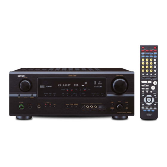
ENGLISH Getting Started Thank you for choosing the DENON AVR-2106 A/V Surround Receiver. This remarkable component has been engineered to provide superb surround sound listening with home theater sources, such as DVD, as well as providing outstanding high fidelity reproduction of your favorite music sources. -
Page 5: Cautions On Installation
Preparing the remote control unit The included remote control unit (RC-1015) can be used to operate not only the AVR-2106 but other remote control compatible DENON components as well. In addition, the memory contains control signals for other remote control units, so it can be used to operate non-DENON remote control compatible products. -
Page 6: Inserting The Batteries
ENGLISH Getting Started Inserting the batteries q Remove the remote control unit’s rear Notes on batteries: cover. • Replace the batteries with new ones if the set does not operate even when the remote control unit is operated nearby the unit. (The included batteries are only for verifying operation.) •... -
Page 7: Remote Control Unit
• The main zone output can be turned on and off with the MAIN button. Easy Setup and Operation • This section contains the basic steps necessary to configure the AVR-2106 according to your Remote control signal listening room environment and the source equipment and loudspeakers you are using. -
Page 8: Speaker System Layout
/ohms) are unit and switch the power back on. If the protection circuit is activated again even though there are no problems with the wiring or the ventilation around the unit, switch off the power and contact a DENON service center. - Page 9 2106 Power Amp Assign. mode allows you to power bi-amp-capable speakers with two amplifier channels ( page 47). Be sure to consult the owner’s manual of your bi-amp-capable speakers Surround speaker for further information before proceeding. systems AVR-2106 ( L ) ( R ) > < > <...
-
Page 10: Connecting A Dvd Player And Monitor Tv
Easy Setup and Operation Connecting a DVD player and monitor TV • To connect the video output from the DVD player to the AVR-2106, you only need to choose one connection type. Component video connection offers the best quality (and is required for progressive DVD playback), followed by S-Video, while composite video offers the lowest picture quality of the three connection types. -
Page 11: Auto Setup / Room Eq
Easy Setup and Operation POWER SPEAKER A ON/STANDBY SETUP MIC Auto Setup / Room EQ The Auto Setup and Room EQ function of this unit performs an analysis of the speaker system and measures the acoustic characteristics of your room to permit an appropriate automatic setting. -
Page 12: Starting Auto Setup
ENGLISH Easy Setup and Operation Starting Auto Setup SETUP Press the button. • The “System Setup” menu appears. CURSOR D D Press the button to select “Auto ENTER Setup/Room EQ”, then press the • The “Auto Setup/Room EQ” menu appears. CURSOR D D Press the button to select “Auto... -
Page 13: About Error Messages
Easy Setup and Operation About error messages • These error screens may be displayed when performing Auto Setup measurement and the automatic measurements can not be completed because of the speaker arrangement, measurement environment, or other factors. Please check the following matters, reset the pertinent items, and measure again. -
Page 14: Playing A Dvd With Surround Sound
ENGLISH Easy Setup and Operation CURSOR D D Press the button to select from the following three items based on the CURSOR F F measurement results, then press the button. Store: Store the checked measurement values. All parameters are stored. Retry: Perform the measurement again. -
Page 15: The Video Conversion Function
If this happens, connect a commercially available video stabilizer, etc., with a TBC (time base corrector) function between the AVR-2106 and the VTR, or if your VTR has a TBC function, turn it on. On screen display signals Signals input to the AVR-2106... -
Page 16: Connecting A Tv/Dbs Tuner
• With discs on which special copyright protection measures have been taken, the digital signals may not be output from the DVD player. In this case, connect the DVD player’s analog multi- channel output to the AVR-2106’s EXT. IN terminals for playback. Also refer to your DVD player’s operating instructions. -
Page 17: Connecting A Dvd Recorder
NOTE: • When recording to a DVD recorder, it is necessary that the type of cable used with the playback source equipment be the same type that is connected to the AVR-2106 VCR-1 (to 2) OUTPUT terminal. Example: VCR-1 IN... -
Page 18: Connecting A Tape Deck
AUDIO IN NOTE: • Do not connect the output of the component connected to the OPTICAL 3 OUT terminal on the AVR-2106’s rear panel to any terminal other than the OPTICAL 3 IN terminal ( Turntable (MM cartridge) AUDIO OUT... -
Page 19: Connecting The Antenna Terminals
Connecting the XM terminal • AVR-2106 is the XM Ready ® receiver. You can receive XM Satellite Radio ® by connecting to the XM Connect-and-Play™ (sold separately) and subscribing the XM service. -
Page 20: Connecting The Rs-232C Terminal
( operating mode. • When a sold separately room-to-room remote control unit (DENON RC-616, 617 or 618) is wired and connected between the MAIN ZONE and ZONE2, the remote-controllable devices in the power from the external control. -
Page 21: Zone2 Speaker Out Connections
Connecting Other Sources ZONE2 speaker out connections • When the power amplifier is assigned to the ZONE2 output channel at “Power Amp Assign.” in the “System Setup” menu, the surround back speaker terminals can be used as the ZONE2 speaker out terminals ( page 38). -
Page 22: Basic Operation
ENGLISH Basic Operation Playback INPUT MODE ANALOG MASTER VOLUME FUNCTION DIMMER STATUS VIDEO SELECT MAIN EXT. IN SELECT PHONES SPEAKER SURROUND MODE Playing the input source Select the input source to be played. Example: CD (Main unit) (Remote control unit) To select the input source when ZONE2/REC OUT is selected, press the MAIN button, then operate the input function selector. -
Page 23: Listening Over Headphones
The display brightness changes in four steps (bright, medium, dim and off). Input mode The AVR-2106 has an AUTO signal detection mode that automatically identifies the type of incoming audio signals, but is also equipped with a manual mode that can be switched according to the type of input audio signals. -
Page 24: Surround
SURROUND PARAMETER Surround Playing audio sources (CDs and DVDs) 2-channel playback modes • The AVR-2106 is equipped with 2-channel playback modes exclusively for music. • Select the mode to suit your tastes. 2 PURE DIRECT mode Use this mode to achieve good quality 2-channel sound while watching images. -
Page 25: Dolby Pro Logic Ii X (Pro Logic Ii ) Mode
Basic Operation Dolby Pro Logic x (Pro Logic ) mode • To play in the PL x mode, set “S. BackSp” at the “Speaker Configuration” setting to “1sp” or “2sp”. • To play in the PL x mode, set “Surround Back” at the “Power Amp Assign.”... -
Page 26: Dts Neo:6 Mode
ENGLISH Basic Operation FUNCTION INPUT MODE SURROUND MODE STANDARD SELECT SURROUND PARAMETER DTS NEO:6 mode STANDARD Press the button to select the DTS NEO:6 mode. The mode switches as shown below each time the button is pressed. DOLBY PL DTS NEO:6 Play a program source. -
Page 27: Dolby Digital Mode And Dts Surround
Basic Operation Dolby Digital mode and DTS surround (only with digital input) Select an input source set to digital (COAXIAL/ OPTICAL) ( page 42). Example: DVD (Main unit) (Remote control unit) INPUT MODE Press the button to set the input mode to “AUTO”... -
Page 28: Night Mode
ENGLISH Basic Operation FUNCTION INPUT MODE STATUS STANDARD/NIGHT 2 Checking the input signal The input signal can be checked by pressing the remote control unit’s ON SCREEN button. SIGNAL: Displays the type of signal (DTS, DOLBY DIGITAL, PCM, etc.). Displays the input signal’s sampling frequency. FORMAT: Displays the input signal’s number of channels. -
Page 29: Adjusting The Audio Delay
• The audio delay setting does not apply when playing in the EXT. IN mode or in the analog input direct, pure direct or stereo mode (TONE DEFEAT “ON”). DENON original surround modes This unit is equipped with a high performance DSP (Digital Signal Processor) which uses digital signal processing to synthetically recreate the sound field. -
Page 30: Dsp Surround Simulation
ENGLISH Basic Operation SURROUND MODE SURROUND PARAMETER SELECT DSP surround simulation 2 To operate the surround mode and the surround parameters from the remote control unit Select the surround mode for the input channel. (Remote control unit) The surround mode switches in the following order each time the DSP SIMULATION button is pressed: MONO MOVIE ROCK ARENA... -
Page 31: Room Eq Setting
Basic Operation Room EQ setting 2 Operate the Room EQ from the remote control unit SURROUND PARAMETER Press the button. • The surround parameter screen appears. CURSOR D D Press the button to select “Room EQ”. CURSOR F F Press the button to select the equalizer setting. -
Page 32: Tone Control Setting
ENGLISH Basic Operation TONE CONTROL SELECT TONE DEFEAT Tone control setting 2 Adjusting the sound quality (tone) The tone control function will not work in the PURE DIRECT or DIRECT mode. TONE CONTROL Press the button. The tone switches as follows each time the TONE CONTROL button is pressed. -
Page 33: Listening To The Radio
Basic Operation FUNCTION BAND PRESET • ON/STANDBY POWER TUNING Listening to the radio Auto preset memory • This unit is equipped with a function for automatically searching for FM broadcast stations and storing them in the preset memory. • The “Auto tuner preset” operation can also be performed at “System setup”... -
Page 34: Manual Tuning
ENGLISH Basic Operation FUNCTION BAND PRESET STATUS ON/STANDBY SHIFT TUNING POWER Manual tuning Set the input source to “TUNER”. BAND Watching the display, press the select the desired band (AM or FM). MODE Press the button to set the manual tuning mode. -
Page 35: Xm Satellite Radio
Basic Operation XM Satellite Radio 2 Introducing XM Satellite Radio There’s a world of audio listening pleasure beyond AM and FM. XM Satellite Radio. Select from over 150 channels of music, news, sports, comedy, talk, and entertainment. Coast-to-coast coverage. Digital quality sound. With all music channels 100% commercial free. -
Page 36: Advanced Operation
ENGLISH Advanced Operation ON SOURCE NUMBER MODE 1 MODE 2 Remote control unit Operating DENON audio components MODE 1 Set the switch to “AUDIO”. MODE 2 Set the switch to the position for the component to be operated (CD, CDR/MD or TAPE). -
Page 37: Preset Memory
Advanced Operation Preset memory • DENON and other makes of components can be operated by setting the preset memory. • This remote control unit can be used to operate components of other manufacturers without using the learning function by registering the manufacturer of the component as shown in the list of preset codes ( End of this manual). - Page 38 ENGLISH Advanced Operation 2. Video disc player (VDP) system buttons ON/SOURCE : Power on/standby : Manual search (forward and reverse) : Stop : Play : Auto search (cue) : Pause 0 ~ 9, +10 : Number 3. Video deck (VCR) system buttons ON/SOURCE : Power on/standby : Manual search (forward and reverse) : Stop...
-
Page 39: Punch Through
: Volume up/down • For CD, CDR, MD and TAPE components, the buttons can be operated in the same way as for DENON audio components page 33). • A TV can be operated when the switch is at the DVD/VDP, VCR, TV position. -
Page 40: Multi Zone Music Entertainment System
In this case, surround back speaker out cannot be used for MAIN ZONE. • When a sold separately room-to-room remote control unit (DENON RC-616, 617 or 618) is wired and connected between the MAIN ZONE and ZONE2, the remote-controllable devices in the MAIN ZONE can be controlled from ZONE2 using the remote control unit. - Page 41 Advanced Operation 2 When using the SURR.BACK/ZONE2 amplifier as the ZONE2 • The SPEAKER OUT, LINE OUT and PRE OUT terminals can be used simultaneously in ZONE2. • To use the ZONE2, turn on the ZONE2 button. • The output of the ZONE2 SPEAKER OUT terminals can be adjusted with the remote control unit’s ZONE2 VOLUME button. [System configuration and connections example] Using this unit’s internal amplifier as the ZONE2.
-
Page 42: Outputting A Program Source To Amplifier, Etc., In A Different Room (Zone2 Mode)
ENGLISH Advanced Operation FUNCTION ZONE2/REC SELECT ZONE2 POWER SPEAKER Outputting a program source to amplifier, etc., in a different room (ZONE2 mode) ZONE2/REC SELECT Press the button to display the “ZONE2 SOURCE” on the display. The display switches as follows each time the button is pressed. -
Page 43: Other Functions
Advanced Operation Other functions Playing one source while recording another (REC OUT mode) ZONE2/REC SELECT Press the button to display the “RECOUT SOURCE” on the display. The display switches as follows each time the button is pressed. ZONE2 FUNCTION Turn the knob to select the source you want to output appears on the display. -
Page 44: Navigating Through The System Setup Menu
On screen display and front display The AVR-2106 is equipped with an intuitive and easy-to-understand on screen display, and is equipped with an alphanumeric front panel display that can also be used to check and adjust settings. -
Page 45: Input Setup
• The “Input Setup” menu appears. • The OPTICAL 3 terminal on the AVR-2106’s rear panel is equipped with an optical digital output terminal for recording digital signals on a CD recorder, MD recorder or other digital recorder. -
Page 46: Setting The Function Rename
ENGLISH Advanced Setup – Part 1 Setting the Component In Assign. This setting assigns the color difference (component) video input terminals of the AVR-2106 for the different input sources. CURSOR D D Press the button to select “Component In Assign.” at the “Input Setup”... -
Page 47: Setting The Video Input Mode
Advanced Setup – Part 1 Setting the Video Input Mode Select the input signal to be output to the composite S-Video and component monitor output terminals using the video conversion function. CURSOR D D Press the button to select “Video Input Mode” at the “Input Setup” ENTER menu, then press the button. -
Page 48: Advanced Playback
ENGLISH Advanced Setup – Part 1 Advanced playback Setting the Audio Delay • When watching a DVD or other video source, the picture on the monitor may seem delayed with respect to the sound. In this case, adjust the audio delay to delay the sound and synchronize it with the picture. -
Page 49: Option Setup
Advanced Setup – Part 1 Option Setup Setting the Trigger Out Setup • Two 12 V DC Trigger Outputs on the rear panel can be used to control other devices with compatible trigger inputs, such as motorized screens, motorized screen masking, motorized drapes, and other trigger-controlled devices. -
Page 50: Setting The Power Amp Assign
ENGLISH Advanced Setup – Part 1 Setting the Power Amp Assign. Make this setting to switch the power amplifier for the surround back channel to ZONE2 or Bi-Amp. SPEAKER OUT Power Amp PRE-OUT Assign. S.BACK/ZONE MAIN ZONE ZONE2 Surround back 7.1ch system –... -
Page 51: Advanced Setup - Part 2
Advanced Setup – Part 2 This Speaker Setup section describes the procedures to make speaker settings manually (without using the Auto Setup function), as well as to make manual changes to settings that have already been made by the Auto Setup function. Speaker Setup Setting the Speaker Config. -
Page 52: Setting The Delay Time
ENGLISH Advanced Setup – Part 2 Setting the Delay Time Input the distance between the listening position and each speaker to set the delay time for the surround playback. Preparations: Measure the distances between the listening position and the speakers. Center Subwoofer Listening position... -
Page 53: Setting The Crossover Frequency
Advanced Setup – Part 2 • To cancel the settings, press the CURSOR H H button to select “Level Clear” on the “Channel Level” screen, then make the settings again. • When adjusting the level of an active subwoofer system, you may also need to adjust the subwoofer’s own volume control. - Page 54 ENGLISH Advanced Setup – Part 2 2 Assignment of low frequency signal range The only signals produced from the subwoofer channel are LFE signals (during playback of Dolby Digital or DTS signals) and the low frequency signal range of channels set to “Small” in the setup menu.
-
Page 55: Others Setup
Advanced Setup – Part 2 Others Setup Setting the Manual EQ Setup Adjust the tone of the various speakers except subwoofer speaker while listening to the sound (music). CURSOR D D Press the button to select “Auto Setup/Room EQ” at the “System Setup” ENTER menu, then press the button. -
Page 56: Setting The Direct Mode Setup
ENGLISH Advanced Setup – Part 2 • The Equalizer setting of “Normal”, “Flat” and “Front” can be selected after performing the Auto Setup. • When the speaker set as “None” with the Auto Setup is change to on manually, the equalizer of “Normal”, “Front” and “Flat”... -
Page 57: System Setup Items And Default Values
Advanced Setup – Part 2 System setup items and default values (set upon shipment from the factory) 1. Auto Setup / Room EQ Auto Setup / Room EQ Set this to switch the surround back Power Amp 1 Auto Setup channel’s power amplifier for ZONE2 or Bi- Assign. - Page 58 ENGLISH Advanced Setup – Part 2 3. Input Setup Input Setup Digital In This assigns the digital input terminals for the Assign. different input sources. Ext In SW Sets the Ext. In Subwoofer terminal playback level. Level Input The playback level can be corrected individually for the Function different input sources.
-
Page 59: Troubleshooting
< > • ends of batteries inserted • Insert batteries properly. in reverse. • AVR-2106’s XM terminal and the • Check that the connection are XM Connect-and-Play antenna is correct. not properly connected. • The signal cannot be received. • Reposition your XM Connect-and- Play antenna. -
Page 60: Additional Information
ENGLISH Additional Information Optimum surround sound for different sources There are currently various types of multi-channel signals (signals or formats with more than two channels). 2 Types of multi-channel signals Dolby Digital, Dolby Pro Logic, DTS, high definition 3-1 signals (Japan MUSE Hi-Vision audio), DVD-Audio, Super Audio CD, MPEG multi-channel audio, etc. - Page 61 6.1 channels but also with conventional 2- to 5.1-channel sources. Furthermore, all the DENON original surround modes ( page 26) are compatible with 7.1-channel playback, so you can enjoy 7.1-channel sound with any signal source.
- Page 62 Surround The AVR-2106 is equipped with a digital signal processing circuit that lets you play program sources in the surround mode to achieve the same sense of presence as in a movie theater.
- Page 63 • There are two types of DVD Dolby surround recording signals. q 2-channel PCM stereo signals w 2-channel Dolby Digital signals • When either of these signals is input to the AVR-2106, the surround mode is automatically set to Dolby Pro Logic the DOLBY/DTS SURROUND mode is selected.
- Page 64 ENGLISH Additional Information [3] DTS-ES Extended Surround™ DTS-ES Extended Surround is a new multi-channel digital signal format developed by Digital Theater Systems Inc. While offering high compatibility with the conventional DTS Digital Surround format, DTS-ES Extended Surround greatly improves the 360- degree surround impression and space expression thanks to further expanded surround signals.
- Page 65 Additional Information Surround modes and parameters Mode FRONT L/R CENTER SURROUND L/R DIRECT/PURE DIRECT STEREO EXTERNAL INPUT DOLBY PRO LOGIC DOLBY PRO LOGIC DTS NEO:6 DOLBY DIGITAL DTS SURROUND 5CH/7CH STEREO ROCK ARENA JAZZ CLUB VIDEO GAME MONO MOVIE MATRIX VIRTUAL C : Signal / Adjustable E : No signal...
-
Page 66: Specifications
ENGLISH Specifications 2 Audio section • Power amplifier Rated output: Front: 100 W + 100 W 135 W + 135 W Center: 100 W 135 W Surround: 100 W + 100 W 135 W + 135 W Surround Back: 100 W + 100 W 135 W + 135 W Dynamic power: 120 W x 2 ch... - Page 67 2 List of preset codes / Liste de codes préréglés Denon 014, *[111] Aiwa Hitachi 006, 011 Konka 012, 013 Magnavox Mitsubishi Panasonic Philips 005, 015, 016, 017 Pioneer 003, 008 Sanyo Sony 002, 019, 020 Toshiba 001, 021, 022...
- Page 68 ENGLISH Optonica Panasonic 024, 049, 064, 066, 067, 068, 069, 107 Perdio Pentax 009, 013, 023, 058, 090 Philco 015, 016, 049 Philips 015, 021, 042, 049, 105 Pilot Pioneer 005, 013, 029, 036, 037, 038, 045, 085 Portland 025, 055, 090 Proscan 063, 080 Pulsar...
- Page 69 Futuretech 020, 036, 037, 040, 044, 058, 066, 088, 119, 120, 125, 147 Goldstar 000, 015, 029, 031, 039, 048, 051, 056, 057, 067, 068, 069, 116 Grundy Hitachi 029, 031, 051, 052, 070, 111, 112, 113, 124, *[134] Hitachi Pay TV Infinity 017, 071 Janeil...
- Page 70 Sierra III Sony 049, 067 STS1 STS2 STS3 SRS4 Technisat 077, 078, 079, 081, 082 Toshiba 047, 050 Uniden Denon *[111] Aiwa 001, 035, 043 Burmster Carver 003, 035 Emerson 004, 005, 006, 007 Fisher 003, 008, 009, 010 018, 019...
- Page 71 Magnavox Marantz Onkyo 016, 018 Optimus 007, 008 Panasonic Philips Pioneer 007, 008, 009 Sony 013, 014, 015 Technics Victor Wards Yamaha 010, 011 *[ ] : Preset codes set upon shipment from the factory. *[ ] : Les codes préréglés diffèrent en fonctiom des livraison de l’usine.
- Page 72 TOKYO, JAPAN www.denon.com Denon Brand Company, D&M Holdings Inc. Printed in China 00D 511 4329 009...