Table of Contents
Advertisement
Quick Links
Advertisement
Table of Contents

Related Manuals for Husqvarna 331R


Summary of Contents for Husqvarna 331R
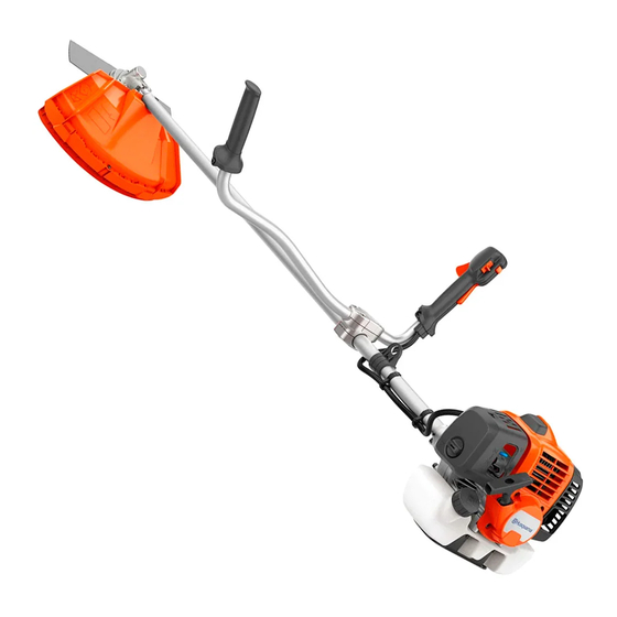
- Page 1 Workshop manual 331R, 333R Mark II English 1296 - 001 - 27.09.2019...
-
Page 2: Table Of Contents
Contents 1 Introduction 1.1 Document description..........3 1.2 Target group............3 1.3 Revisions..............3 1.4 Safety..............3 1.5 Servicing tools............3 2 Safety 2.1 Safety definitions............4 2.2 General safety instructions........4 2.3 Special safety instructions........4 2.4 Symbols on the product......... 4 3 Servicing schedule 4 Servicing data 4.1 Servicing data............ -
Page 3: Introduction
1.5 Servicing tools The manual gives information about necessary servicing tools. Always use original tools from Husqvarna. 1296 - 001 - 27.09.2019 Introduction - 3... -
Page 4: Safety
2 Safety 2.1 Safety definitions Use a protective helmet in locations where objects can fall on you. Use approved Warnings, cautions and notes are used to point out hearing protection. Use approved eye specially important parts of the manual. protection. WARNING: Used if there is a risk of injury or death for the operator or bystanders if the instructions in the manual are not obeyed. -
Page 5: Servicing Schedule
3 Servicing schedule The descriptions of the maintenance procedures are in the operator's manual. Maintenance task After Every Every Before each hours hours Clean the external surfaces. √ Clean the air filter. Replace if it is necessary. √ Make sure that the harness frame is not damaged. √... -
Page 6: Servicing Data
4 Servicing data 4.1 Servicing data 3 - 4 Nm 4 mm 2 - 3 Nm 4 mm 3 - 5 Nm 4 mm 18 - 20 Nm 19 mm 6 - 8 Nm 4 mm 6 - 8 Nm 4 mm 4 - 6 Nm 4 mm... - Page 7 1.5 - 2.5 Nm 4 mm 6 - 8 Nm 5 mm 1.2 - 2 Nm 4 mm 1.5 - 2 Nm 4 mm 4 - 6 Nm 5 mm 3 - 5 Nm 4 mm 1.2 - 2 Nm 5 mm 3 - 5 Nm 4 mm...
-
Page 8: Servicing Tools
5 Servicing tools 5.1 Servicing tools 8 - Servicing tools 1296 - 001 - 27.09.2019... - Page 9 Item Description Use to Article number Driver Remove the starter pawl assembly 510 13 90-01 Piston stop Lock the piston 522 43 18-01 Ignition tester Examine the ignition spark 502 71 13-01 Ignition cable pliers Repair the ignition cable 502 50 06-01 Flywheel removal tool Remove the flywheel 502 51 49-02...
-
Page 10: Function Overview
• Always use a fuel container with an antispill valve. • If Husqvarna two-stroke oil is not available, use a • If there is some fuel on the container, remove the two-stroke oil of good quality for air-cooled engines. -
Page 11: Repair Instructions
7 Repair instructions 7.1 Product overview for repair instructions 1. Starter 4. Carburetor 2. Muffler 5. Clutch drum cover and clutch drum 3. Air filter and air filter holder 6. Ignition module 1296 - 001 - 27.09.2019 Repair instructions - 11... -
Page 12: To Clean And Examine The Product Parts
7.3 Starter 7. Centrifugal clutch 8. Flywheel 7.3.1 To disassemble the starter 9. Cylinder and piston 10. Crankcase and crankshaft WARNING: Use protective glasses to prevent 11. Fuel tank injury to the eyes if the recoil spring ejects. 12. Handle 13. - Page 13 3. Pull out the starter rope approximately 30 cm. Put 7.3.2 To replace the recoil spring in the starter your thumb on the starter pulley. Put the starter rope housing in the groove in the starter pulley. Let the starter To disassemble the 1.
- Page 14 5. Put the starter rope through the opening in the 4. Make a small knot on the starter rope and pull the starter housing and the opening in the bearing knot into the handle. journal. 7.3.4 To assemble the starter 1.
-
Page 15: Muffler
5. Assemble in the opposite sequence to how it was disassembled. Note: There is a second muffler cover on the 333R Mark II model. These illustrations shows the 331R model. 3. Install the muffler in the opposite sequence. 7.4.2 To clean and examine the muffler WARNING: Risk of burn injury or fire. -
Page 16: Air Filter
4. Make sure that the muffler is correctly attached to 3. Soak the air filter with oil. Put the air filter in a plastic the product. bag and put about a tablespoon of oil into the bag. Servicing tools make sure to use the correct oil, see on page 8 . - Page 17 7. Use the pressure vacuum tester to increase the 4. Assemble the fuel tank cap. Make sure the seal (F) pressure to 0.5 bar in the fuel tank. is not damaged. 8. Remove your thumb from the hole in the fuel tank cap.
-
Page 18: Carburetor
3. Tighten the hose clamp. Make sure that the filter 7.7.2 The function of the carburetor cannot move off the tube. Carburetor structure on page 18 for the Refer to illustration for this text. 7.7 Carburetor Before the engine is started, the air in the carburetor must be removed. - Page 19 7.7.3 Overview of the carburetor 1. Seal ring 2. Gasket 3. Diaphragm 4. Screen 5. Fuel inlet 6. Valve, inlet 7. Gasket 8. Diaphragm 9. Pump 1296 - 001 - 27.09.2019 Repair instructions - 19...
- Page 20 7.7.4 To disassemble the carburetor 4. Remove the 2 screws (F) and remove the air filter housing (G), if it is necessary. 1. Turn the engine to get access to the air filter assembly. Remove the air filter assembly (A, B, C 5.
- Page 21 9. Carefully lift up check valve (T) with your nails. a) Examine the connection points against the Clean the check valve housing and make sure that control diaphragm for wear. the channels are open. Carefully push the short b) Examine the grooves for the needle valve for sides of the check valve (U) together to make sure wear.
- Page 22 b) Examine the distance piece for cracks and 7.7.6 To do a pressure test of the carburetor damage that can result in leakage. Replace the To disassemble the 1. Remove the carburetor. Refer to distance piece if it is damaged. carburetor on page 20 .
-
Page 23: Ignition System
5. Measure the height (A) of the lever arm and adjust 3. Turn the idle adjustment screw counterclockwise the height if it is necessary. Correct height is until the cutting attachment stops. 4±0.5mm. Technical data on page 45 for the Note: Refer to recommended idle speed. - Page 24 3. Connect the ignition tester to the spark plug cap and 3. Turn the spring to remove it from the cable. ground the clip to the cylinder. 4. Cut approximately 5 mm of the cable. ~ 5 mm 4. Use the knob to adjust the distance between the 2 electrodes.
- Page 25 6. Put the spring into the new hole. 10. Use the pliers or a screwdriver to align the spring with the hole in the spark plug cap. 7. Put the cable with the open spring into the other slot in the pliers. Close the pliers to bend the spring. CAUTION: Be very careful to prevent damage to the spark plug cap.
- Page 26 5. Disconnect the throttle wire from the carburetor. 7. Remove the 3 screws (A) and remove the muffler cover (B). 6. Disconnect the cables. 8. Remove the 4 screws ( C and D), and remove the cylinder cover. 9. Remove the 4 screws (F) and remove the clutch drum housing (G).
- Page 27 12. Remove the screws, washers, cables and the 15. Hold the flywheel puller and loosen and remove the ignition module. flywheel nut. 13. Remove the 2 screws and the 2 washers that hold 16. Attach the center unit to the flywheel puller. Hold the the centrifugal clutch.
- Page 28 3. Attach the flywheel and the centrifugal clutch with 5. Use a feeler gauge to make sure that the distance the spacers and screws as shown in the illustration. between the ignition module and the flywheel is 0.3-0.5 mm. 6. Install the remaining parts in the opposite sequence. Note: Turn the clutch until you can see the arrows To disassemble the ignition system on page Refer to...
-
Page 29: Centrifugal Clutch
7.9 Centrifugal clutch 5. Remove the clamp (B) from the clutch drum housing. Do not remove the screw (A). Use pliers to remove the large snap ring (C). Remove the bushing 7.9.1 To disassemble the clutch (D). Use pliers to remove the small snap ring (E). 1. -
Page 30: Cylinder And Piston
3. Measure the diameter of the clutch drum. Replace 7.10.2 To disassemble the cylinder and piston the clutch drum if the diameter is more than 78.5 To get access to the 1. Remove parts as given in cylinder and piston on page 30 to get access to the cylinder and piston. - Page 31 6. Push the wrist pin from the piston with a punch of 7.10.3 To clean the cylinder and piston the correct dimension. CAUTION: Clean carefully. The soft aluminum parts are easily damaged. • Remove the carbon deposits from these parts: 7.
- Page 32 • Make sure that the cylinder does not have score • Put the piston ring in the cylinder and measure the marks. space with an air gap tool. The space must not be more than 1 mm. 7.10.5 To examine the piston •...
- Page 33 7.10.6 To assemble the cylinder and piston 5. Attach the G snap rings. 1. Carefully put the piston ring on the piston. Make sure that you do not cause damage to the piston ring or the piston. 2. Lubricate the needle bearing with two-stroke oil and put it into the connecting rod.
-
Page 34: Crankshaft And Crankcase
7.11 Crankshaft and crankcase 9. Use a hot air gun to increase the temperature of the crankcase and the crankcase cover to 110°C. Hit the crankcase and the crankcase cover against a 7.11.1 To disassemble the crankshaft and wooden block to make the bearings fall out. crankcase To get access to the crankshaft and crankcase, you must remove all components of the product. - Page 35 7.11.2 To clean and examine the crankshaft and a) Put the bearings in the crankcase and the crankcase cover. crankcase b) Use a hot air gun to increase the temperature of The crankshaft can not be repaired, it must be replaced the crankcase and crankcase cover to 110°C.
- Page 36 a) Lubricate the stub axle of the crankshaft and the 4. Lubricate the crankshaft journal with some drops of large end of the connecting rod with some drops two-stroke oil and move the crankcase cover into of two-stroke oil. Do not put oil on the threads. position.
-
Page 37: Harness Frame
d) Attach the flywheel. 8. Assemble the remaining parts in the opposite sequence to how they were disassembled. 7.12 Harness frame 7.12.1 To remove the engine from the harness frame 1. Drain the fuel tank. 2. Pull up the knob and remove the shaft. 7. -
Page 38: Handle And Throttle Trigger
7.13 Handle and throttle trigger 4. To remove the stop switch, use a screwdriver to push the lock mechanism of the stop switch (G). 7.13.1 To disassemble and assemble the handle 5. Assemble the handle and throttle trigger in the and throttle trigger opposite sequence. -
Page 39: Gearbox
7.14 Gearbox 7.14.2 To disassemble the gearbox 1. Remove the gearbox from the product. Refer to 7.14.1 To remove the gearbox remove the gearbox on page 39 . 1. Put a rod through the hole (B) to lock the axle. 2. - Page 40 6. Remove the input shaft assembly (O) from the 3. Put on protective gloves. Use a hot air gun to gearbox. increase the temperature of the angle gear to approximately 140°C. 4. Put the output shaft into the gearbox. Make sure that the bearings are in their correct positions.
- Page 41 9. Attach the snap ring (L) for the bearing on the output shaft. 10. Attach the bushing (K) on the output shaft. 11. Attach the grease plug (N). 12. Attach the snap ring (M) for the bearings on the input shaft. 13.
-
Page 42: Troubleshooting
8 Troubleshooting 8.1 Troubleshooting Start The engine is not easy to start. The stop screw for the throttle does not operate correctly. Blocked fuel filter. Blocked fuel hose. Air in fuel pipes. Incorrect/unsatisfactory fuel. The needle valve is defective. The lever arm of the needle valve is damaged. The lever arm of the needle valve does not operate correctly. - Page 43 Idle speed (low speed) The engine stops at idle speed. The stop screw for the throttle does not operate correctly. Blocked fuel filter. Blocked fuel hose. Air in fuel pipes. The needle valve is defective. Defective heat insulation seal. The lever arm of the needle valve is too high. The lever arm of the needle valve does not operate correctly.
- Page 44 Increase and decrease speed The engine stops when the speed is de- The lever arm of the needle valve is too high. creased. The lever arm of the needle valve does not operate correctly. The needle valve is worn. Object in the needle valve groove. The engine cannot increase speed.
-
Page 45: Technical Data
9 Technical data 9.1 Technical data 331R 333R Mark II Engine Cylinder displacement, cm 32.6 32.6 Cylinder bore, mm Stroke, mm Idle speed, rpm 3000±300 3000±300 Recommended max speed, rpm 10600 10600 Max. engine output, according to ISO 8893, kW @ rpm... - Page 46 46 - Technical data 1296 - 001 - 27.09.2019...
- Page 47 1296 - 001 - 27.09.2019 Technical data - 47...
- Page 48 1141484-26 2019-10-07...