Table of Contents
Advertisement
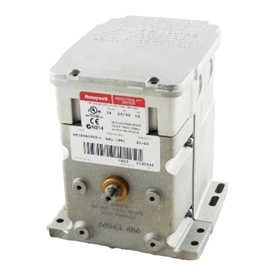
Honeywell
M9484 AND M9494 MODUTROL MOTORS ARE LOW
VOLTAGE, REVERSING PROPORTIONAL CONTROL
ACTUATORS FOR VALVES, DAMPERS AND AUXIL-
IARY EQUIPMENT. THEY ARE ESPECIALLY DE-
SIGNED FORCOMMERCIALOR INDUSTRIALOILOR
GAS BURNER CONTROL SYSTEMS.
•i Replace M941 motors.
Oil immersed motor and gear train for reliable per-
formance and long life.
Wiring Box provides NEMA 3 weather protection.
Actuator motor and circuitry operate from 24 volts
AC. Models available with factory installed transformer,
or internal transformer can be field added.
Quick-connect terminals standard - screw terminal
adapter available.
Cl
Adapter Bracket for matching shaft height of older
motors is standard with replacement motors.
Field adjustable stroke (90" to 160') models avail-
able.
q
Nominal timing of 30 seconds for 90" and 60 sec-
onds for 160" stroke is standard. Other timings are
available.
q
Available accessories include valve and damper
linkages, explosion proof housing, and auxiliary
,
switches.
Field addable interface modules can be mounted in
wiring box to upgrade actuator to Series 70 (electronic)
control.
•i
Models available with tapped output shaft.
dard timings.
minute timings for 160" stroke.
S.M.
Rev. 11-90
Form Number 63-2195-l
@Honeywell Inc. 1990
Advertisement
Table of Contents

Related Manuals for Honeywell M9484


Summary of Contents for Honeywell M9484
- Page 1 Honeywell M9484 AND M9494 MODUTROL MOTORS ARE LOW VOLTAGE, REVERSING PROPORTIONAL CONTROL ACTUATORS FOR VALVES, DAMPERS AND AUXIL- IARY EQUIPMENT. THEY ARE ESPECIALLY DE- SIGNED FORCOMMERCIALOR INDUSTRIALOILOR GAS BURNER CONTROL SYSTEMS. •i Replace M941 motors. Oil immersed motor and gear train for reliable per- formance and long life.
- Page 2 IF YOU HAVE ADDITIONAL QUESTIONS, NEED FURTHER INFORMATION, OR WOULD LIKE TO COMMENT ON OUR PRODUCTS OR SERVICES, PLEASE WRITE OR PHONE: YOUR LOCAL HONEYWELL RESIDENTIAL AND BUILDING CONTROLS SALES OFFICE (CHECK WHITE PAGES OF PHONE DIRECTORY). HONEYWELL INC., 1885 DOUGLAS DRIVE NORTH...
- Page 3 Controller. ES6501 17 Explosion-proof Housing-Encloses motor for use in explosive atmospheres. Not for use with Controller. son Electric Co. Requires Honeywell 7617DM Cou- pling. Q607 External Auxiliary Switch-Controls auxiliary in wiring box of M9lXX motor. Can be used in place equipment as a function of motor position.
- Page 4 ADAPTER BRACKET FIG. 1-UIMtNSIUNS IN In. NOTE: M9481, M9491 do not have auxiliary shaft. All other dimensions are the same. LOCATION install the Modutrol motor in any location except where weather protection. acid fumes or other deteriorating vapors might attack the metal parts, or in atmospheres of escaping gas or the Always install motors with the crankshaft horizontal.
- Page 5 ADAPTER BRACKET motor and the equipment, raises the shaft height ptthe- M9484 motor by 0.75 inch to match that of the M941 motor. This is required on all valve linkage applications, Q607 External Auxiliary Switch applications, and on some damper linkage applications (either to provide clearance for the crank arm to rotate through the downward position, or to allow the damper linkage to reach the shaft).
- Page 6 WIRING BOX MOTOR MACHINE SCREWS OR BOLTS. LTS SECURING BRACKET TO LINKAGE. TIGHTEN AFTER SECURING MOTOR TO THE BRACKET USING FOUR BOLTS PROVIDED. FIG. 4-MOTOR MOUNTING ON VALVE LINKAGE,. Figs. 5 and 6 show internal schematics. Do not exceed the motor ratings in any installation. The motor terminals are quick-connects located on top 5.
- Page 7 YELLOW LEAD BLUE LEAD CLOSE LIMIT WIRING SHOULD BE NEC CLASS 1 UNLESS POWER SUPPLY MEETS CLASS 2 REQUIREMENTS. TAPE UNUSED LEADS. MAKE CERTAIN THE CURRENT DRAW OF THE EXTERNAL CIRCUIT IS LESS THAN CONTACT RATING OF SWITCH. ON TWO-SWITCH MOTORS SECOND SWITCH HAS BLACK LEADS WITH BLUE, YELLOW.
- Page 8 CONNECTIONS AUXILIARY SWITCH The M9484F has 2 internal auxiliary switches which may be used to prove low fire and high fire positions. 1. To prove fire use red (common) and yellow wires connected to outer (left) switch. This switch makes red to supplies to de-energize the yellow and breaks red to blue as motor closes.
- Page 9 MOVE SCREWDRIVER AT TOP ONLY TO ADJUST CAM: STRAIGHT BLADE SCREWDRIVER OUTER STROKE OUTER CAM ADJUST CAMS RY SWITCH CAMS POWER SUPPLY. PROVIDE DISCONNECT MEANS AND OVERLOAD PROTECTION AS REQUIRED. NOTE: CAMS ARE OFFSET TRANSFORMER MAY BE EXTERNAL OR INTERNAL. PROVIDE BETTER VIEW OF BACK CAM.
- Page 10 The M9484 can also be used with some electronic When the value of the controlled medium changes, the controllers which provide a 4-20 mA control output. lt is...
- Page 11 SERIES 99 CONTROLLER MOTOR OPTIONAL CONNECTIONS WITH 2-135 OHM POTENTIOMETERS IN SERIES. SERIES 90 CONTROLLER MOTOR SERIES 90 HIGH LIMIT CONTROL PROTECTION REQUIRED. TRANSFORMER TRANSFORMER MAY BE INTERNAL OR EXTERNAL TO MOTOR. POWER SUPPLY. PROVIDE DISCONNECT MEANS AN,, OVERLOAD PROTECTION AS REQUIRED. TRANSFORMER MAY BE INTERNAL OR EXTERNALTO MOTOR.
- Page 12 220738A Adapter Bracket or 221455A crank arm if crank VALVE APPLICATION arm must rotate through the bottom plane of the motor (for When installing a M9484, M9494 motor in a valve ap- damper applications). plication which has a QlOO, Q601 or 0618 it will be...