
Related Manuals for Emerson RXi2-BP


Summary of Contents for Emerson RXi2-BP
- Page 1 RXi2-BP Hardware Reference Manual GFK-3187B November 2020 RXi2-BP HARDWARE REFERENCE MANUAL...
-
Page 2: Table Of Contents
RXi2-BP Hardware Reference Manual Contents GFK-3187B November 2020 Contents Section 1: Introduction ............1 Document History ....................2 Capability and Compatibility ................2 Software Requirements ..................2 Features ......................2 Section 2: Unpacking and Inspection........3 Package Contents ....................3 Available Options and Accessories ................ - Page 3 RXi2-BP Hardware Reference Manual Contents GFK-3187B November 2020 Remove and Attach Cover ................. 14 Replace the Real-Time Clock (RTC) battery ............15 Inserting and removal of µSD Card ..............17 Change M.2 Mass Storage Device ..............18 Section 6: Hardware Interfaces ..........20 External Interfaces .....................
- Page 4 RXi2-BP Hardware Reference Manual Contents GFK-3187B November 2020 Section 9: Specifications ............36 Power Consumption ..................36 Temperature ..................... 37 Shock and Vibration ..................37 Altitude ......................38 Regulations and Certifications ................38 Battery ......................38 Technical Specifications..................38 Section 10: Troubleshooting ..........39 10.1 Unexpected Restarts When Booting ..............
- Page 5 Changes, modifications, and/or improvements to equipment and specifications are made periodically and these changes may or may not be reflected herein. It is understood that Emerson may make changes, modifications, or improvements to the equipment referenced herein or to the document itself at any time. This document is intended for use by trained personnel familiar with the Emerson products referenced herein.
-
Page 6: Introduction
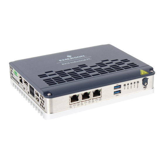
CEC10 COM Express type 10 carrier board • Industrial grade enclosure with heat sink for the module and carrier components This chapter describes the features, capabilities, and compatibilities of the RXi2-BP IPC and its components. Figure 1: RXi2-BP IPC Introduction... -
Page 7: Document History
The CEC10 COM Express carrier board is also compliant with the PICMG COM Express Module Base Specification R3.0 Type 10 (refer to the documentation located at http://www.picmg.org). The RXi2-BP power supply module provides a voltage input of nominal 24 V DC (± 25%) and supports under and overvoltage supervisory, and protection against reverse polarity. -
Page 8: Unpacking And Inspection
°F) and above. Be careful and do not touch the RXi2-BP IPC with bare fingers. Si le RXi2-BP IPC est opérée à une température ambiante élevée jusqu'à 70 ° C (149 ° F), la surface du boîtier, en particulier le dissipateur thermique, peut atteindre une température de 85 °... -
Page 9: Esd And Emi
Any operational system with cables for I/O signals, connectivity, or peripheral devices provide an entry point for ESD and EMI. If Emerson has not manufactured the complete system, including the enclosure and cables, then it is the responsibility of the system integrator and end-user to protect their system against potential problems. -
Page 10: Unpack And Inspect
If evidence of damage or rough handling is found (usually in the form of bent component leads or loose socketed components), notify the shipping service as soon as possible and contact Emerson for additional instructions. Depending on the severity of the damage, it may be necessary to return the product to the factory for repair. -
Page 11: Handling
RXi2-BP IPC with bare fingers. Si le RXi2-BP IPC est opérée à une température ambiante élevée jusqu'à 70 ° C (149 ° F), la surface du boîtier, en particulier le dissipateur thermique, peut atteindre une température de 85 ° C (185 °... -
Page 12: Mounting
RXi2-BP Hardware Reference Manual Section 3 GFK-3187B November 2020 Section 3: Mounting RXi2-BP IPC cooling is designed for wall mounted orientation of the box. There are two possible mounting options: • Din Rail Mounting • Mounting Panel DIN Rail Mounting... - Page 13 IPC. • If the DIN connector is 15 mm in height: use two DIN rail supports in a stack to increase the height to offset the bottom of the IPC. Figure 3: RXi2-BP IPC DIN Rail Mounting Options Mounting...
-
Page 14: Panel Mounting
3. For regular mounting, secure the mounting plate and IPC through the top and bottom center holes. For more rugged applications, secure the mounting plate with the four provided M3x6 screws in all four corners of the mounting panel. Figure 4: Attaching Mounting Plate RXi2-BP IPC Figure 5: RXi2-BP IPC DIN Rail pre-mounting Mounting... -
Page 15: Clearances Requirements To All Mounting Options
November 2020 Clearances requirements to all mounting options Figure 6 shows the optimal clearances requested by RXi2-BP to operate within full thermal specifications and is applicable for DIN rail and panel mount option. Any deviation in requested clearance will result in reduced thermal performance and must be evaluated by the customer based on the final setup. -
Page 16: Installation And Startup
Do not restore power until all components are fitted correctly into the system and all connections have been made properly. Required Materials The following items are required to start the RXi2-BP IPC in a standard configuration: • Power supply •... -
Page 17: Power Supply
A few seconds after powering up, the RXi2-BP IPC system UEFI Firmware banner will display on the screen. If you do not see any error messages up to this point, the RXi2-BP IPC is running properly and ready to be configured for your application. -
Page 18: Uefi Firmware Setup
RXi2-BP Hardware Reference Manual Section 4 GFK-3187B November 2020 UEFI Firmware Setup 4.5.1 Entering UEFI Firmware Setup To enter setup during the initial startup sequence: press the Delete or F2 key during the startup sequence. Adhere to the applicable on-screen messages when prompted. -
Page 19: Installation And Replacement Procedures
Remove and Attach Cover 1. Shut down the system and remove power from the RXi2-BP IPC. 2. Loosen the four screws on the RXi2-BP IPC’s top cover and remove it (Figure 7). Figure 7: IPC Cover Installation and Replacement Procedures... -
Page 20: Replace The Real-Time Clock (Rtc) Battery
WARNING There is a danger of explosion if the battery is incorrectly replaced. Replace only with the same or equivalent to Rayovac BR2032 or CR2032. Dispose of used batteries according to Emerson provided instructions and applicable local regulations. Battery can only be exchanged by skilled person. - Page 21 RXi2-BP Hardware Reference Manual Section 5 GFK-3187B November 2020 NOTICE The information described in this section applies to service technicians only. 1. Follow instructions on how to remove the cover, see Section 5.1, Remove and Attach Cover. Figure 9 2. Locate the RTC battery ( Figure 9: RTC Battery Note: The gap pad is already removed.
-
Page 22: Inserting And Removal Of Μsd Card
RXi2-BP Hardware Reference Manual Section 6 GFK-3187B November 2020 Inserting and removal of µSD Card Unscrew µSD card lid with Tx 8 screwdriver until µSD opening is accessible. Inserting µSD card into the opening (Figure 10). Figure 10: Inserted µSD card before plugging in 3. -
Page 23: Change M.2 Mass Storage Device
WARNING Verify that the power supply is turned off while installing boards or modules into the RXi2-BP IPC. 1. To remove the cover, follow instructions in Section 5.1 Remove and Attach Cover. - Page 24 RXi2-BP Hardware Reference Manual Section 6 GFK-3187B November 2020 3. Remove the M.2 mass storage device (Figure 14). 4. Remove the thermal gap pads from the M.2 mass storage device and store them for reuse on a replacement device Figure 14: Screw Removal 4.
-
Page 25: Hardware Interfaces
6.1.1 Power-In The corresponding plug must be a Phoenix Contact “1748367” or equivalent. RXi2-BP can be powered with a DC power supply with 24V (+-25%) and at least delivering 1.8 A. Figure 17: 24V DC-IN Signal Name Pin (left to right) -
Page 26: Leds
5 sec to force the RXi2-BP IPC to shut down immediately without operating system support. State S5 (Soft-off mode) will switch off the CPU core power and reset the RXi2-BP IPC. The state S5 is indicated with a yellow power LED. At this stage, it is possible to reactivate the RXi2-BP IPC by pressing (short push) the Power button. -
Page 27: Ethernet Ports
If disabled, the button has no functionality. 6.1.4 Ethernet Ports The RXi2-BP provides four Ethernet ports: three RJ45 ports at the front, and one at the bottom. All Ethernet ports support 10/100/1000 Base-T. For a proper 100/1000 Mbit connection, a CAT5 cable is recommended. -
Page 28: Usb2 / Usb3.2Gen1
6.1.5 USB2 / USB3.2Gen1 The RXi2-BP provides two USB2 (USB 3 & 4) and two USB3.2 Gen1 (USB 1 & 2) ports. All four are USB type-A connectors. Each port (USB2 and USB3.2 Gen1) is protected with an electrical fuse rated up to 1 A. -
Page 29: Displayport
SSRX- SSRX+ SSTX- SSTX+ 6.1.6 DisplayPort RXi2-BP provides one Display port (DP1) interface that provides signals for connecting either a suitable DP-monitor or an adaptor to several other display standards. Figure 23: DisplayPort Pinout Signal Name Pin TxD0+/- TxD1+/- TxD2+/-... -
Page 30: Serial Ports
6.1.7 Serial Ports The RXi2-BP provides two serial interfaces, one configured to RS232 (P0) and one configurable to RS422 or RS485 [2W/4W] (P1). The connector is a Phoenix contact “1953745” or equivalent and mates with Phoenix contact “1952296.” Two mating plugs are shipped with the system. -
Page 31: Μsd Slot
SATA interface; no NVMe modules are supported. Form factors 2042, 2060, and 2080 are supported and 2042 is the default. If you require to change from form factor 2042 to any other please contact Emerson support for guidance. -
Page 32: Temperature Sensor
November 2020 6.3.2 Temperature Sensor UEFI Firmware sets up two thermal zones on the RXi2-BP carrier board that can be observed with an EMC2113 device. This device contains internal temperature sensors. Three external temperature sensors are also connected. All external sensors are grouped as one thermal group and placed so that the hottest point can be observed, no matter the mounting style. -
Page 33: Hardware And Firmware Programmable Devices
RXi2-BP Hardware Reference Manual Section 7 GFK-3187B November 2020 Section 7: Hardware and Firmware Programmable Devices SMBUS Devices Device Address [7b format] Function PI6CDBL402B Clock Buffer 4x TCA9554 SMB Port Expander EMC2213 Temperatur Controller PI7C9X2G608GP PCIe Switch I2C Devices Device... -
Page 34: Pcie Ports
RXi2-BP Hardware Reference Manual Section 7 GFK-3187B November 2020 PCIe Ports Source Port Destination Diodes PI7C9X2G608GP (PCIe Switch Upstream COMe PCIe port) COMe PCIe Intel I210 #1 (GBE) COMe PCIe Intel I210 #2 (GBE) COMe PCIe RiserSlot PI7C9X2G608GP PCIe Intel I210 #3 (GBE) - Page 35 RXi2-BP Hardware Reference Manual Section 7 GFK-3187B November 2020 Function Connected Vendor ID/System Device Bus:Dev:Func mC10L19 Encryption controller AMD / 1022 15DF B:0.2 USB controller AMD / 1022 15E0 B:0.3 USB controller AMD / 1022 15E1 B:0.4 Multimedia controller AMD / 1022 15E2 B:0.5...
-
Page 36: Thermal Performance
(milliseconds/microseconds). This strategy allows an increase in observable performance, while simultaneously averaging out to a lower heat dissipation. RXi2-BP and the AMD Ryzen processor that it uses supports these techniques, and they are enabled in UEFI settings by default. It is highly recommended to keep these settings enabled so that performance and thermal advantages of the architecture can be utilized. -
Page 37: Temperature Monitoring And Protection
November 2020 8.1.3 Temperature Monitoring and Protection The RXi2-BP can monitor critical temperatures on-module and on-carrier and is configured to protect itself from an overtemperature condition. IPC peripheral circuitry provides two static thermal zones (TZE1 and TZE2) and the CPU circuitry provides also two thermal zones (TZCP and TZD1). -
Page 38: Thermal Design Strategy
8.2.1 Thermal Guidance The following is thermal guidance for the different RXi2-BP processor SKUs. It is based on zero airflows, and even a slight movement of air will dramatically increase the operating temperature range. The graph below shows the maximum ambient temperature range, based on CPU SKU and application workload. -
Page 39: Thermal Test Data
Instead, the strategy is to provide test data for several specific test cases that allow the user to make first estimates and then perform real testing. For a more detailed Thermal Test Report and further thermal design guidance please contact Emerson technical support. - Page 40 RXi2-BP Hardware Reference Manual Section 8 GFK-3187B November 2020 Linux R1505G PACEdge Max 16GB (text Ubuntu 60 °C (2C, 4T, 10W) workload mode) 20.04 SXGA V1605B 16GB (graphics Linux Win Idle 74 °C (4C, 8T, 25W) mode) SXGA V1605B Win Max...
-
Page 41: Specifications
Section 9 GFK-3187B November 2020 Section 9: Specifications This chapter provides specifications and other useful information about RXi2-BP. The RXi2-BP must be connected from PowerIn port (Pin3, see Power-In for details) to FGND to ensure proper EMC protection. Power Consumption... -
Page 42: Temperature
Storage 5 to 95% rH, non-condensing, at 40°C (104 °F) Operating Shock and Vibration Shock and vibration values for the RXi2-BP IPC are provided in the following tables for both mounting variants. DIN Rail IEC 60068-2-27: 1987 (test Ea) Impact, operating... -
Page 43: Altitude
UL 62368-1 (UL file number E214940) Battery The RXi2-BP IPC contains a BR2032 lithium coin battery. The maximum current used by the mC10L19 module is 6µA. Depending on the operating hours and temperature, the estimated battery life is 2 to 10 years. -
Page 44: Section 10: Troubleshooting
RXi2-BP Hardware Reference Manual Section 10 GFK-3187B November 2020 Section 10: Troubleshooting 10.1 Unexpected Restarts When Booting AMD Ryzen processors have an increased range of power consumption, where for a very short period of time (milliseconds) they can consume significantly more power than the average power consumption. -
Page 45: General Contact Information
Emerson reserves the right to modify or improve the designs or specifications of the products mentioned in this manual at any time without notice. Emerson does not assume responsibility for the selection, use, or maintenance of any product.