Table of Contents
Advertisement
Quick Links
Operation, Parts, Repair
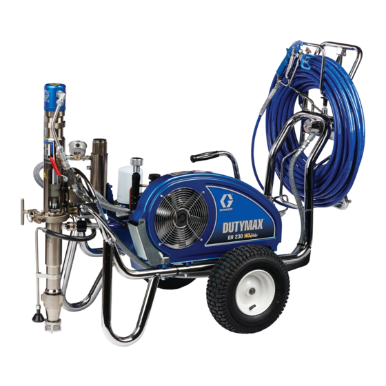
DutyMax EH
Hydraulic Sprayer
For professional use only.
Not approved for use in explosive atmosphere or hazardous locations.
For portable airless spraying of architectural paints and coatings.
3300 psi (22.8 MPa, 228 bar) Maximum Working Pressure
Important Safety Instructions
Read all warnings and instructions in this manual and in related manuals.
Be familiar with the controls and the proper usage of the equipment.
Save these instructions.
Use only genuine Graco replacement parts.
The use of non-Graco replacement parts may void warranty.
230DI
™
3A4401A
ti29528a
EN
Advertisement
Table of Contents

Related Manuals for Graco DutyMax EH 230DI


Summary of Contents for Graco DutyMax EH 230DI
- Page 1 Read all warnings and instructions in this manual and in related manuals. Be familiar with the controls and the proper usage of the equipment. Save these instructions. ti29528a Use only genuine Graco replacement parts. The use of non-Graco replacement parts may void warranty.
-
Page 2: Table Of Contents
Graco Standard Warranty ........ -
Page 3: Warnings
Warnings Warnings The following warnings are for the setup, use, grounding, maintenance, and repair of this equipment. The exclamation point symbol alerts you to a general warning and the hazard symbols refer to procedure-specific risks. When these symbols appear in the body of this manual or on warning labels, refer back to these Warnings. - Page 4 All parts of the spray system, including the pump, hose assembly, spray gun, and objects in and around the spray area shall be properly grounded to protect against static discharge and sparks. Use Graco conductive or grounded high-pressure airless paint sprayer hoses.
- Page 5 Check hoses and parts for signs of damage. Replace any damaged hoses or parts. • This system is capable of producing 3300 psi (22.8 MPa, 228 bar). Use Graco replacement parts or accessories that are rated a minimum of 3300 psi (22.8 MPa, 228 bar).
- Page 6 Do not kink or over-bend the hose. • Do not expose the hose to temperatures or to pressures in excess of those specified by Graco. • Do not use the hose as a strength member to pull or lift the equipment.
- Page 7 Warnings ENTANGLEMENT HAZARD Rotating parts can cause serious injury. • Keep clear of moving parts. • Do not operate equipment with protective guards or covers removed. • Do not wear loose clothing, jewelry or long hair while operating equipment. • Equipment can start without warning.
-
Page 8: Component Identification
Component Identification Component Identification bar/MPa ti29581a Hydraulic Oil Cap / Dipstick Pressure Gauge Hose Reel Lock Pressure Control Hose Reel Handle Hydraulic Pump Valve Hydraulic Oil Filter ProConnect Paint Filter Displacement Pump Inlet Strainer Electric Motor On/Off Switch Gun Trigger Lock Grounding Clamp Serial Number Tag Prime/Drain Valve... -
Page 9: Grounding
Grounding Grounding the pail on a non-conductive surface, such as paper or cardboard, which interrupts grounding continuity. The equipment must be grounded to reduce the risk of static sparking. Static sparking can cause fumes to ignite or explode. Grounding provides an escape wire for the electric current. -
Page 10: Setup
Remove Tip Guard. Screw inlet strainer to bottom of suction hose and hand tighten securely. Check hydraulic oil level. Add only Graco Hydraulic Oil, ISO Grade 46, 169236 (5 gallon/18.9 liter) or 207428 (1 gallon/3.8 liter). Hydraulic tank capacity is 1.25 gallon (4.75 liters). -
Page 11: Pressure Relief Procedure
Setup Pressure Relief Procedure Follow the Pressure Relief Procedure whenever you see this symbol. Safe Range (cold) ti5243a Attach sprayer grounding clamp to earth ground. This equipment stays pressurized until pressure is manually relieved. To help prevent serious injury from pressurized fluid, such as skin injection, splashing fluid and moving parts, follow the Pressure Relief Procedure when you stop spraying... -
Page 12: Startup
Startup Startup Plug cord into outlet. Turn motor ON. Place displacement pump in grounded metal pail partially filled with flushing fluid. Attach ground wire to pail and to earth ground. ti29582a Set hydraulic pump valve ON (hydraulic motor is now active). ti9692a Turn prime valve down. - Page 13 Startup Disengage trigger lock. 10. Inspect fittings for leaks. If leaks occur, turn sprayer OFF immediately. Perform Pressure Relief Procedure, page 11. Trigger lock engaged Tighten leaky fittings. Repeat Startup procedure steps 2-8. If no leaks, Trigger lock disengaged continue to trigger gun until system is thoroughly flushed.
-
Page 14: How To Spray
How to Spray How to Spray Switch Tip and Guard How to Adjust the Spray ™ Assembly Pattern To adjust the spray pattern direction, relieve pressure. Loosen the tip guard retaining nut (B). Turn the tip guard/tip groove horizontally (C) for a horizontal Perform Pressure Relief Procedure, pattern and vertically (A) for a vertical page 11. -
Page 15: Spray
How to Spray Spray Spray test pattern. Increase pressure to eliminate heavy edges. Use smaller tip size if pressure adjustment can not eliminate heavy edges. ti13025a Clear Tip Clogs ti13030a Release trigger, engage trigger lock. Hold gun perpendicular, 10-12 in. (25-30 Rotate Switch Tip. - Page 16 How to Spray Hose Reel Pull reel handle up and turn clockwise to reel in hose. To avoid injury, keep your head clear of hose reel while winding up hose. Make sure hose is routed through hose guide. ti29583a NOTE: The hose reel can be locked into two positions: Usage and Storage.
-
Page 17: Clean Up
Clean Up Clean Up Hold gun against pail. Disengage trigger lock. Turn pressure control up until motor begins to drive pump. Trigger gun until flushing fluid appears. Perform Pressure Relief Procedure, page 11. Remove Guard and SwitchTip. PAINT ti5272a Move gun to waste pail, hold gun against pail, trigger gun to thoroughly flush system. - Page 18 Clean Up Raise displacement pump above 10. Unscrew and remove inlet strainer. flushing fluid and run sprayer for 15 to 30 Clean and replace strainer if necessary. seconds to drain fluid. Turn hydraulic valve OFF. Turn engine OFF or turn electric motor OFF and unplug.
-
Page 19: Maintenance
AFTER EACH 500 HOURS OR 3 MONTHS DAILY: Check hose for wear and damage. OF OPERATION: Replace hydraulic oil and filter with Graco hydraulic oil 169236 (5 DAILY: Check trigger lock for proper gallon/20 liter) or 207428 (1 gallon/3.8 liter) operation. -
Page 20: Troubleshooting
Shut off sprayer. Add fluid*. See page 10 Belt worn or broken or off Replace belt Hydraulic pump worn or Bring sprayer to Graco damaged distributor for repair Dried paint seized paint pump Service pump. See Pump, page Hydraulic motor not shifting Set pump valve OFF. - Page 21 Power switch is not ON Turn power switch ON Tripped circuit breaker Check circuit breaker at power source. Reset motor switch *Check hydraulic fluid level often. Do no allow it to become too low. Use only Graco hydraulic fluid, page 10. 3A4401A...
-
Page 22: Dutymax Eh230Di Procontractor Series Parts
KEY, square 3/16 x hp (includes all parts 1.25 listed on this page) 17N231 CORDSET, adapter, 119a 15E669 MOTOR, electric 3 HP, India 230V AC Danger and Warning labels are available at no 100002 SCREW, set cost 15B804 LABEL, Graco 3A4401A... - Page 23 DutyMax EH230DI ProContractor Series Parts Notes 3A4401A...
- Page 24 DutyMax EH230DI ProContractor Series Parts EH230DI Frame and Belt Guard Parts Ref. Torque Ref. Torque Inflate tires to 25-35 psi 120-130 in-lb (13.6 - 14.7 N•m) (1.7-2.4 bar) ti25333a 3A4401A...
- Page 25 DutyMax EH230DI ProContractor Series Parts Parts List Ref. Part Description Qty. Ref. Part Description Qty. 17N233 LABEL, brand, side 16D576 LABEL, made in USA with (EH230DI) global component 24M086 RAIL, belt guard, assy 110963 SCREW, cap, flange 17D108 FRAME, cart, weldment head 248973 GUARD, belt assembly, 260212 SCREW, hex washer hd,...
- Page 26 DutyMax EH230DI ProContractor Series Parts DutyMax Reservoir & Filter Parts Ref. Torque Ref. Torque 58-62 in-lb (6.6 - 7.0 N•m) 15-25 in-lb (1.7 - 2.8 N•m) Apply Loctite 242 Apply Loctite 277 90-110 in-lb (10.2 - 12.4 N•m) 110-120 in-lb (12.4 - 13.6 N•m) 355-395 in-lb (40.1 - 44.6 N•m) 63 ref 103 ref...
- Page 27 198585 LABEL, hydraulic fluid, 246173 FILTER, oil, spin on 15E599 HOUSING, filter 15A464 LABEL, control 15G331 PLUG, pipe 189892 LABEL, Graco 244067 FILTER, fluid 15E410 PULLEY, fan 15C766 TUBE, diffusion 15K440 LABEL, brand, EH 117285 PACKING, o-ring cooling 15C765 CAP, filter...
- Page 28 DutyMax EH230DI ProContractor Series Parts Hydraulic Motor & Displacement Pump Parts Ref. Torque Ref. Torque 145-155 ft-lb (196.6 - 210.2 N•m) 140-160 in-lb (15.8 - 18.1 N•m) 12-18 ft-lb (16.3 - 24.4 N•m) 90-110 in-lb (10.2 - 12.4 N•m) 290a 290b 290c 116 ref...
- Page 29 34 for parts Included in Hydraulic Motor Repair Kit, 288760 129 15B063 LABEL, warning, hot + Included in Seal Kit 246174 surface * Included in Check Valve Repair Kit 24M725 17D061 LABEL, brand, front 157 15B804 LABEL, Graco 3A4401A...
- Page 30 DutyMax EH230DI ProContractor Series Parts DutyMax EH230DI Sprayer - Spray Gun & Hose Qty. Ref. Part No. Description 202a 240797 HOSE, grounded, nylon; 3/8 in. ID; cpld 3/8-18 npsm; 50 ft (15 m); spring guards both ends 202b 241735 HOSE, grounded, nylon; 1/4 in. 202a ID;...
- Page 31 DutyMax EH230DI ProContractor Series Parts ProContractor Series Hose Reel Parts Ref. Torque Ref. Torque 120-130 in-lb (13.6 - 14.7 N•m) 130-150 in-lb (14.7 - 16.9 N•m) 25-35 ft-lb (33.9 - 47.5 N•m) Apply Loctite 277 ti25338a Ref. Part Description Qty. Ref.
-
Page 32: Spray Gun Parts
Spray Gun Parts Spray Gun Parts ti04730a Ref. Part Description Qty. Ref. Part Description Qty. 102924 SPRING 237680 TEXTURE GUN 189990 SPRING ADJUSTER BODY 110637 ADJUSTING SCREW 237260 NEEDLE AND SEAL 24R913 FLUID HOUSING KIT (parts not sold 112774 SCREW, 1/4-20 separately) 189974 GUN TRIGGER VALVE SEAT... - Page 33 Spray Gun Parts Notes 3A4401A...
-
Page 34: Pump Parts
Pump Parts Pump Parts Torque to 55 ± 3 ft/lbs (75 ± 4 N•m) Torque to 200 ± 10 ft/lbs (271 ± 20 N•m) Torque to 140 ± 10 in/lbs (16 ± 1 N•m) Soak in SAE 30W oil for 1 hour prior to assembly ti25249a 3A4401A... - Page 35 Pump Parts Pump Parts List Ref. Part Description Qty. Ref. Part Description Qty. 189588 GLAND, packing, 17D125 CYLINDER, pump female 287817 SLEEVE, cylinder 119636 WIPER, piston 15A303 HOUSING, intake 15F875 PACKING, vee 15J038 SEAT, carbide 287388 VALVE, piston 107098 PACKING, o-ring 118601 BALL, ceramic 118602 BALL, ceramic 15J792 NUT, packing...
-
Page 36: Repair
Repair Repair The needle and seat are available only as a kit which includes the valve seat, gasket, needle, seal retainer, and seal. The Standard Needle and Seat Kit, 237398, ti04731b has the number 090 stamped on the needle Unscrew the valve seat (2a). Remove and the seat. - Page 37 Repair ti04736a While supporting the spring guide (16) to prevent bending the needle, loosen the ti04732a setscrews (17). Remove the spring guide (16). Remove the screws (24). ti04734a ti04733a Loosen the setscrew (15). Pull the fluid housing (22) away from the gun body (1). Remove the needle (2c).
- Page 38 Repair Lightly grease the small end of the needle (2c) and then guide it into the large end of the fluid housing (22). ti03974a Cleaning ti03676a Clean all parts and cavities thoroughly with a Place the gasket (2b) on the valve seat compatible solvent.
- Page 39 Repair Push the fluid housing (22) onto the gun body (1) until fully seated. Tighten the Ref. Action setscrew (15) to 30--40 in--lb (3.4--4.5 Seat against needle stem N•m). Fill the setscrew cavity with Apply light strength Loctite; Torque petroleum jelly. alternately and evenly to 25-30 in-lb (2.8 - 3.4N•m) Ref.
- Page 40 Repair Test the Gun Before Position the trigger (25) on the gun body. Insert the pivot pin (28) into the top hole Regular Use (A) and secure with the screw (29) on the other side. Place an e-clip (27) on one end of the trigger pin (18).
-
Page 41: Pump
Repair Pump Removal Flush pump. Perform Pressure Relief Procedure, ti8829a page 11. Remove rod couplers. ti18418a ti8830a Remove paint hose fitting and paint hose from pump fitting. Remove pin. ti8828a ti8831a NOTE: Support pump with your hand before Slide coupler cover up to fully expose rod opening t-handle. - Page 42 Repair Disassemble Pump Open clamp. Remove packing nut and throat adjustment spacer. ti8833a Remove pump from unit. ti25168a Unscrew cylinder from intake valve. ti8832a Installation If needed, place pump rod in adjustment casting and pull pump to extend rod. ti8834a Reverse removal steps to reassemble pump.
- Page 43 Repair Remove piston rod from sleeve. NOTICE If using a pick to remove the O-ring use care to avoid damage to the machined surfaces. ti8849a Do not clean or wipe the piston valve threads. Cleaning the piston valve threads could destroy the special sealing patch and cause the piston valve to come loose during operation, possibly causing a pump burst and personal injury.
- Page 44 Repair Assemble Pump Clean and inspect parts. (The piston has a special thread locking/sealing patch. Do not remove the patch. The patch If applicable, soak leather packings in allows for disassembly/assembly SAE 30W oil for one hour before procedures before it is necessary to assembly.
- Page 45 Repair Leather Packings ti24892a Assemble leather throat packings soaked earlier. ti25175a Leather Packings Install ball in piston rod. Apply thread sealant to piston valve threads; ensure that none gets on the ball. ti25175a Loosely install packing nut with o-ring onto cylinder. ti25176a Torque to 55 ±...
- Page 46 Repair Install o-rings inside cylinder and on sleeve. Slide sleeve into bottom of cylinder. Replace o-ring if necessary. ti25180a Grease o-ring and place on outside diameter ring groove. ti8859a Apply liberal amounts of grease or oil to piston packings. ti25181a ti25179a Grease top inch or two of piston rod that will go through the cylinder throat...
- Page 47 Repair 10. Clean seat thoroughly. Reassemble 11. Torque foot valve to 200 ± 15 ft-lb (271 ± intake valve with a seat, ball, and new 20 N•m). o-ring. Seat may be flipped over and used on other side. ti25183a ti25182a 3A4401A...
- Page 48 Repair 12. Torque packing nut to 140 ± 10 in-lbs (16 13. Storage ± 1 N•m). ti25185a Throat Packing Adjustment When pump packings begin to leak after much use, perform Pressure Relief Procedure, page 11, and tighten packing nut ti25184a down until leakage stops or lessens.
-
Page 49: Technical Specifications
Technical Specifications Technical Specifications DutyMax EH230DI ProContractor Series Metric Maximum fluid working pressure 3300 psi 22.8 MPa, 228 bar Hydraulic reservoir capacity 1.25 gallons 4.75 liters Engine 2.2 kW 3.0 HP Voltage, Amperage Frequency Phase 220 VAC, 15.0 A 220 VAC, 15.0 A, 50 Hz, 1 phase 50 Hz, 1 phase Maximum tip size... - Page 50 Technical Specifications EH230 OEM Hydraulic Hydraulic Return, 37º flare, Inlet, 37º flare, 3/4-16 UNF-2A 3/4-16 UNF-2A 1.813 in. (46.05 mm) Mounting Screw (4), Socket Cap Screw 1in. 2.25 in. 3/8-16 UNC (57.15 mm) Quick Connect Paint Outlet, 3/8-18 NPT Male Paint Suction Fitting, 1.312-121/2 UN-2A ti24313b...
-
Page 51: Graco Standard Warranty
Graco’s written recommendations. This warranty does not cover, and Graco shall not be liable for general wear and tear, or any malfunction, damage or wear caused by faulty installation, misapplication, abrasion, corrosion, inadequate or improper maintenance, negligence, accident, tampering, or substitution of non-Graco component parts. -
Page 52: Graco Information
Original instructions. This manual contains English. MM 3A4401 Graco Headquarters: Minneapolis International Offices: Belgium, China, Japan, Korea GRACO INC. AND SUBSIDIARIES • P.O. BOX 1441 • MINNEAPOLIS MN 55440-1441 • USA Copyright 2016, Graco Inc. All Graco manufacturing locations are registered to ISO 9001. www.graco.com...