Endress+Hauser Levelflex FMP51 Brief Operating Instructions
Profibus pa guided wave radar
Hide thumbs
Also See for Levelflex FMP51:
- Operating instructions manual (254 pages) ,
- Technical information (132 pages) ,
- Brief operating instructions (56 pages)
Table of Contents
Advertisement
Quick Links
Download this manual
See also:
Technical Information
KA01079F/00/EN/14.15
71282359
Products
Brief Operating Instructions
Levelflex FMP51, FMP52,
FMP54
PROFIBUS PA
Guided wave radar
These Instructions are Brief Operating Instructions; they are
not a substitute for the Operating Instructions pertaining to
the device.
Detailed information about the device can be found in the
Operating Instructions and the other documentation:
Available for all device versions via:
– Internet:
www.endress.com/deviceviewer
– Smart phone/tablet: Endress+Hauser Operations App
Solutions
Services
Advertisement
Table of Contents

Related Manuals for Endress+Hauser Levelflex FMP51


Summary of Contents for Endress+Hauser Levelflex FMP51
- Page 1 Operating Instructions pertaining to the device. Detailed information about the device can be found in the Operating Instructions and the other documentation: Available for all device versions via: – Internet: www.endress.com/deviceviewer – Smart phone/tablet: Endress+Hauser Operations App...
- Page 2 Levelflex FMP51, FMP52, FMP54 PROFIBUS PA Order code 00X00-XXXX0XX0XXX Ser. No.: X000X000000 TAG No.: XXX000 Serial number www.endress.com/deviceviewer Endress+Hauser Operations App A0023555 Endress+Hauser...
-
Page 3: Table Of Contents
Levelflex FMP51, FMP52, FMP54 PROFIBUS PA Table of contents Table of contents Important document information ..........4 Symbols . -
Page 4: Important Document Information
Important document information Levelflex FMP51, FMP52, FMP54 PROFIBUS PA Important document information Symbols 1.1.1 Safety symbols Symbol Meaning DANGER! This symbol alerts you to a dangerous situation. Failure to avoid this situation will result in DANGER serious or fatal injury. - Page 5 Levelflex FMP51, FMP52, FMP54 PROFIBUS PA Important document information 1.1.4 Symbols for certain types of information Symbol Meaning Symbol Meaning Permitted Preferred Procedures, processes or actions that Procedures, processes or actions that are permitted. are preferred. Forbidden Procedures, processes or actions that Indicates additional information.
-
Page 6: Basic Safety Instructions
The manufacturer is not liable for damage caused by improper or non-designated use. Verification for borderline cases: ‣ For special measured materials and cleaning agents, Endress+Hauser is glad to provide assistance in verifying the corrosion resistance of wetted materials, but does not accept any warranty or liability. -
Page 7: Workplace Safety
It meets general safety standards and legal requirements. It also complies with the EC directives listed in the device-specific EC Declaration of Conformity. Endress+Hauser confirms this by affixing the CE mark to the device. Endress+Hauser... -
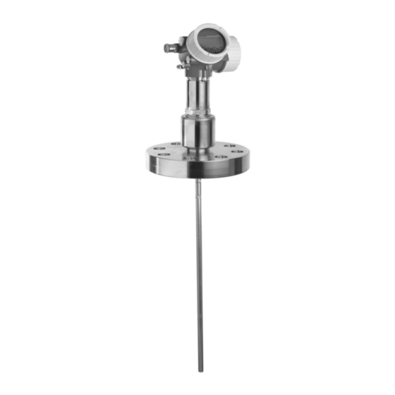
Page 8: Product Description
Product description Levelflex FMP51, FMP52, FMP54 PROFIBUS PA Product description Product design 3.1.1 Levelflex FMP51/FMP52/FMP54/FMP55 A0012399 1 Design of the Levelflex Electronics housing Process connection (here as an example: flange) Rope probe End-of-probe weight Rod probe Coax probe Endress+Hauser... -
Page 9: Incoming Acceptance And Product Identification
): All information about the measuring device is displayed. • Enter the serial number from the nameplates into the Endress+Hauser Operations App or scan the 2-D matrix code (QR code) on the nameplate with the Endress+Hauser Operations App: all the information for the measuring device is displayed. - Page 10 Incoming acceptance and product identification Levelflex FMP51, FMP52, FMP54 PROFIBUS PA 4.2.1 Nameplate Order code: Ser. no.: Ext. ord. cd.: Order code: Ser. no.: Ext. ord. cd.: A0021952 2 Example of a nameplate Order code Serial number (Ser. no.) Extended order code (Ext.
-
Page 11: Storage, Transport
Levelflex FMP51, FMP52, FMP54 PROFIBUS PA Storage, Transport Storage, Transport Storage conditions • Permitted storage temperature: –40 to +80 °C (–40 to +176 °F) • Use the original packaging. Transport product to the measuring point WARNING Housing or probe may be damaged or break away. -
Page 12: Mounting
Mounting Levelflex FMP51, FMP52, FMP54 PROFIBUS PA Mounting Mounting requirements 6.1.1 Suitable mounting position A0012606 3 Mounting requirements for Levelflex Endress+Hauser... - Page 13 Levelflex FMP51, FMP52, FMP54 PROFIBUS PA Mounting Mounting distances • Distance (A) between wall and rod or rope probe: – for smooth metallic walls: > 50 mm (2 in) – for plastic walls: > 300 mm (12 in) to metallic parts outside the vessel –...
- Page 14 Mounting Levelflex FMP51, FMP52, FMP54 PROFIBUS PA 6.1.2 Securing the probe Securing rope probes A0012609 Sag of the rope: ≥ 1 cm per 1m of the probe length (0.12 inch per 1 ft of the probe length) Reliably grounded end of probe...
- Page 15 Levelflex FMP51, FMP52, FMP54 PROFIBUS PA Mounting Securing rod probes • For WHG approvals: For probe lengths ≥ 3 m (10 ft) a support is required. • In general, rod probes must be supported if there is a horizontal flow (e.g. from an agitator) or in the case of strong vibrations.
- Page 16 Mounting Levelflex FMP51, FMP52, FMP54 PROFIBUS PA probe a [mm (inch)] b [mm (inch)] 8 mm (1/3") < 14 (0.55) 8.5 (0.34) 12 mm (1/2") < 20 (0.78) 12.5 (0.52) 16 mm (0.63in) < 26 (1.02) 16.5 (0.65) NOTICE Poor grounding of the end of probe may cause measuring errors.
-
Page 17: Mounting The Device
Levelflex FMP51, FMP52, FMP54 PROFIBUS PA Mounting Mounting the device 6.2.1 Required mounting tools • For mounting thread 3/4": Hexagonal wrench 36 mm • For mounting thread 1-1/2": Hexagonal wrench 55 mm • To shorten rod or coax probes: Saw •... - Page 18 Mounting Levelflex FMP51, FMP52, FMP54 PROFIBUS PA 4 (0.16) 3 mm A0012453 Rope material Torque for set screws 4 mm (0.16 in) 40 mm (1.6 in) 3 mm 5 Nm (3.69 lbf ft) Using an Allen key, loosen the set screws at the end-of-probe weight or the clamping sleeve of the centering disk.
- Page 19 Levelflex FMP51, FMP52, FMP54 PROFIBUS PA Mounting Shortening coax probes Coax probes must be shortened if the distance to the container floor or outlet cone is less than 10 mm (0.4 in). Coax probes can be shortened max. 80 mm (3.2 in) from the end. They have centering units inside, which fix the rod centrally in the pipe.
- Page 20 Mounting Levelflex FMP51, FMP52, FMP54 PROFIBUS PA Mounting rope probes NOTICE Electrostatic discharges may damage the electronics. ‣ Earth the housing before lowering the rope into the vessel. A0012852 When lowering the rope probe into the vessel, observe the following: •...
- Page 21 Levelflex FMP51, FMP52, FMP54 PROFIBUS PA Mounting CAUTION The plugs of the connection cable may be damaged by mechanical stress. ‣ Mount the probe and the electronics housing tightly before connecting the cable. ‣ Lay the cable such that it is not exposed to mechanical stress. Minimum bending radius: 100 mm (4").
- Page 22 Mounting Levelflex FMP51, FMP52, FMP54 PROFIBUS PA 6 Nm 6 Nm (4.42 lbf ft) (4.42 lbf ft) = 100 (4) = 100 (4) 6 Nm 6 Nm (4.42 lbf ft) (4.42 lbf ft) A0014794 5 Connecting the cable. There are the following possibilities:...
- Page 23 Levelflex FMP51, FMP52, FMP54 PROFIBUS PA Mounting max. 350° 8 mm 8 mm A0013713 Unscrew the securing screw using an open-ended wrench. Rotate the housing in the desired direction. Tighten the securing screw (1,5 Nm for plastics housing; 2,5 Nm for aluminium or stainless steel housing).
- Page 24 Mounting Levelflex FMP51, FMP52, FMP54 PROFIBUS PA Tighten the securing clamp again using the Allen key (Torque: 2.5 Nm). Endress+Hauser...
-
Page 25: Post-Installation Check
Levelflex FMP51, FMP52, FMP54 PROFIBUS PA Mounting Post-installation check Is the device undamaged (visual inspection)? Does the device conform to the measuring point specifications? For example: • Process temperature • Process pressure (refer to the chapter on "Material load curves" of the "Technical Information"... -
Page 26: Electrical Connection
Electrical connection Levelflex FMP51, FMP52, FMP54 PROFIBUS PA Electrical connection Connection conditions 7.1.1 Terminal assignment PROFIBUS PA / FOUNDATION Fieldbus A0011341 6 Terminal assignment PROFIBUS PA / FOUNDATION Fieldbus Without integrated overvoltage protection With integrated overvoltage protection Cable screen: Observe cable specifications... - Page 27 Levelflex FMP51, FMP52, FMP54 PROFIBUS PA Electrical connection Terminal for potential equalization line Cable entries Overvoltage protection module Endress+Hauser...
- Page 28 Electrical connection Levelflex FMP51, FMP52, FMP54 PROFIBUS PA 7.1.2 Device plug connectors For the versions with fieldbus plug connector (M12 or 7/8"), the signal line can be connected without opening the housing. Pin assignment of the M12 plug connector Meaning...
-
Page 29: Power Supply
Levelflex FMP51, FMP52, FMP54 PROFIBUS PA Electrical connection 7.1.3 Power supply PROFIBUS PA, FOUNDATION Fieldbus "Power supply; Output" "Approval" Terminal voltage E: 2-wire; FOUNDATION Fieldbus, switch output • Non-Ex 9 to 32 V G: 2-wire; PROFIBUS PA, switch output • Ex nA •... -
Page 30: Connecting The Device
Electrical connection Levelflex FMP51, FMP52, FMP54 PROFIBUS PA External overvoltage protection HAW562 or HAW569 from Endress+Hauser are suited as external overvoltage protection. For detailed information please refer to the following documents: • HAW562: TI01012K • HAW569: TI01013K Connecting the device... - Page 31 Levelflex FMP51, FMP52, FMP54 PROFIBUS PA Electrical connection Strip the cable. Strip the cable ends 10 mm (0.4 in). For stranded cables, also attach wire end ferrules. Firmly tighten the cable glands. A0013837 Connect the cable in accordance with the terminal assignment → 26.
-
Page 32: Post-Connection Check
Integration into a PROFIBUS network Levelflex FMP51, FMP52, FMP54 PROFIBUS PA ≤ 3 (0.12) mm (in) A0013661 Post-connection check Are cables or the device undamaged (visual inspection)? Do the cables comply with the requirements? Do the cables have adequate strain relief? -
Page 33: Set Device Address
Levelflex FMP51, FMP52, FMP54 PROFIBUS PA Integration into a PROFIBUS network GSD file Information and files under: • www.endress.com GSD file version • www.profibus.org Set device address A0015686 7 Address switches in terminal compartment 8.2.1 Hardware adressing Set switch 8 to "OFF". - Page 34 Integration into a PROFIBUS network Levelflex FMP51, FMP52, FMP54 PROFIBUS PA The device restarts automatically. The address remains the same as before (factory setting: 126). Set the required address via the operating menu: "Setup" menu → Device address A0015903 9 Example of software addressing;...
-
Page 35: Commissioning Via Wizard
Levelflex FMP51, FMP52, FMP54 PROFIBUS PA Commissioning via wizard Commissioning via wizard A wizard guiding the user through the initial setup is available in FieldCare and DeviceCare. Connect the device to FieldCare or DeviceCare (for details refer to the "Operating options"... -
Page 36: Commissioning (Via Operating Menu)
Commissioning (via operating menu) Levelflex FMP51, FMP52, FMP54 PROFIBUS PA Commissioning (via operating menu) 10.1 Display and operating module 10.1.1 Display appearance User ABC_ DEFG HIJK LMNO PQRS TUVW A0012635 10 Appearance of the display and operation module for on-site operation Measured value display (1 value max. - Page 37 Levelflex FMP51, FMP52, FMP54 PROFIBUS PA Commissioning (via operating menu) 10.1.2 Operating elements Meaning Minus key For menu, submenu Moves the selection bar upwards in a picklist. A0013969 For text and numeric editor In the input mask, moves the selection bar to the left (backwards).
- Page 38 Commissioning (via operating menu) Levelflex FMP51, FMP52, FMP54 PROFIBUS PA 10.1.3 Opening the context menu Using the context menu, the user can call up the following menus quickly and directly from the operational display: • Setup • Conf. backup disp.
-
Page 39: Operating Menu
Levelflex FMP51, FMP52, FMP54 PROFIBUS PA Commissioning (via operating menu) 10.2 Operating menu Parameter/Submenu Meaning Description Language Defines the operating language of the on-site display. Setup When appropriate values have been assigned toall setup parameters, the measured should be completely configured in a standard application. -
Page 40: Unlock The Device
Commissioning (via operating menu) Levelflex FMP51, FMP52, FMP54 PROFIBUS PA 10.3 Unlock the device If the device has been locked, it must be unlocked before the measurement can be configured. For details refer to the Operating Instructions of the device: BA01006F (FMP51/FMP52/FMP54, PROFIBUS PA) 10.4... -
Page 41: Configuration Of A Level Measurement
Levelflex FMP51, FMP52, FMP54 PROFIBUS PA Commissioning (via operating menu) 10.5 Configuration of a level measurement 20 mA 100% 4 mA A0011360 12 Configuration parameters for level measurements in liquids LN = Length of probe R = Reference point of the measurement... - Page 42 Commissioning (via operating menu) Levelflex FMP51, FMP52, FMP54 PROFIBUS PA Setup → Medium group Select medium group (Others or Water based (DC >= 4)) Setup → Empty calibration Enter the distance E between the reference point R and the minimum level (0%).
-
Page 43: Configuration Of An Interface Measurement
Levelflex FMP51, FMP52, FMP54 PROFIBUS PA Commissioning (via operating menu) 10.6 Configuration of an interface measurement Only devices with the respective software option can be used for interface measurements. This option is selected in the product structure: Feature 540 "Application package", option EB "Interface measurement". - Page 44 Commissioning (via operating menu) Levelflex FMP51, FMP52, FMP54 PROFIBUS PA Setup → Operating mode Select the Interface option. Setup → Tank type Select tank type. Setup → Tube diameter (only if "Tank type" = "Bypass / pipe") Enter the diameter of the bypass or stilling well.
-
Page 45: User-Specific Applications
Levelflex FMP51, FMP52, FMP54 PROFIBUS PA Commissioning (via operating menu) 10.7 User-specific applications For details of setting the parameters of user-specific applications, see separate documentation: BA01006F/00/DE (Operating Instructions FMP51/FMP52/FMP54, PROFIBUS PA) For the Expert submenu refer to: GP01001F/00/DE (Description of Device Parameters FMP5x, PROFIBUS PA) - Page 48 *71282359* 71282359 www.addresses.endress.com...