Endress+Hauser Levelflex HART FMP51 Brief Operating Instructions
Guided wave radar
Hide thumbs
Also See for Levelflex HART FMP51:
- Operating instructions manual (254 pages) ,
- Technical information (132 pages) ,
- Brief operating instructions (48 pages)
Table of Contents
Advertisement
Quick Links
KA01077F/00/EN/17.17
71385688
Products
Brief Operating Instructions
Levelflex FMP51, FMP52,
FMP54
HART
Guided wave radar
These Instructions are Brief Operating Instructions; they are
not a substitute for the Operating Instructions pertaining to
the device.
Detailed information about the device can be found in the
Operating Instructions and the other documentation:
Available for all device versions via:
– Internet:
www.endress.com/deviceviewer
– Smart phone/tablet: Endress+Hauser Operations App
Solutions
Services
Advertisement
Table of Contents

Related Manuals for Endress+Hauser Levelflex HART FMP51


Summary of Contents for Endress+Hauser Levelflex HART FMP51
- Page 1 Operating Instructions pertaining to the device. Detailed information about the device can be found in the Operating Instructions and the other documentation: Available for all device versions via: – Internet: www.endress.com/deviceviewer – Smart phone/tablet: Endress+Hauser Operations App...
- Page 2 Levelflex FMP51, FMP52, FMP54 HART Order code: XXXXX-XXXXXX Ser. no.: XXXXXXXXXXXX Ext. ord. cd.: XXX.XXXX.XX Serial number www.endress.com/deviceviewer Endress+Hauser Operations App A0023555 Endress+Hauser...
-
Page 3: Table Of Contents
User-specific applications ............. . . 54 Endress+Hauser... -
Page 4: Important Document Information
• Inner ground terminal: Connects the protectiv earth to the mains supply. • Outer ground terminal: Connects the device to the plant grounding system. 1.1.3 Tool symbols A0011222 A0011220 A0011219 A0013442 A0011221 Cross-head Flat blade Torx screwdriver Allen key Hexagon wrench screwdriver screwdriver Endress+Hauser... - Page 5 Indicates the non-hazardous area. 1.1.6 Symbols at the device Symbol Meaning Safety instructions Observe the safety instructions contained in the associated Operating Instructions. Temperature resistance of the connection cables Specifies the minimum value of the temperature resistance of the connection cables. Endress+Hauser...
-
Page 6: Basic Safety Instructions
The manufacturer is not liable for damage caused by improper or non-designated use. Verification for borderline cases: ‣ For special measured materials and cleaning agents, Endress+Hauser is glad to provide assistance in verifying the corrosion resistance of wetted materials, but does not accept any warranty or liability. -
Page 7: Workplace Safety
Loss of degree of protection by opening of the device in humid environments ‣ If the device is opened in a humid environment, the degree of protection indicated on the nameplate is no longer valid. This may also impair the safe operation of the device. Endress+Hauser... - Page 8 The measuring system meets the legal requirements of the applicable EC guidelines. These are listed in the corresponding EC Declaration of Conformity together with the standards applied. Endress+Hauser confirms successful testing of the device by affixing to it the CE mark. 2.5.2 EAC conformity The measuring system meets the legal requirements of the applicable EAC guidelines.
-
Page 9: Product Description
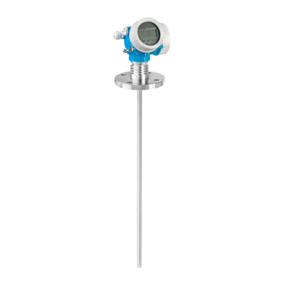
Levelflex FMP51, FMP52, FMP54 HART Product description Product description Product design 3.1.1 Levelflex FMP51/FMP52/FMP54/FMP55 A0012399 1 Design of the Levelflex Electronics housing Process connection (here as an example: flange) Rope probe End-of-probe weight Rod probe Coax probe Endress+Hauser... -
Page 10: Incoming Acceptance And Product Identification
): All information about the measuring device is displayed. • Enter the serial number from the nameplates into the Endress+Hauser Operations App or scan the 2-D matrix code (QR code) on the nameplate with the Endress+Hauser Operations App: all the information for the measuring device is displayed. - Page 11 Only 33 digits of the extended order code can be indicated on the nameplate. If the extended order code exceeds 33 digits, the rest will not be shown. However, the complete extended order code can be viewed in the operating menu of the device in the Extended order code 1 to 3 parameter. Endress+Hauser...
-
Page 12: Storage, Transport
Do not fasten lifting devices (hoisting slings, lifting eyes etc.) at the housing or the probe but at the process connection. Take into account the mass center of the device in order to avoid unintended tilting. ‣ Comply with the safety instructions, transport conditions for devices over 18kg (39.6lbs) (IEC61010). A0013920 Endress+Hauser... -
Page 13: Mounting
Levelflex FMP51, FMP52, FMP54 HART Mounting Mounting Mounting requirements 6.1.1 Suitable mounting position A0012606 3 Mounting requirements for Levelflex Endress+Hauser... - Page 14 • Distance (C) from end of probe to bottom of the vessel: – Rope probe: > 150 mm (6 in) – Rod probe: > 10 mm (0.4 in) – Coax probe: > 10 mm (0.4 in) For coax probes the distance to the wall and to internal fittings is arbitrary. Endress+Hauser...
- Page 15 Make the rope longer than the required measuring range such that there is a sag in the middle of the rope that is ≥ 1cm/(1 m rope length) [0.12 inch/(1 ft rope length)]. Endress+Hauser...
- Page 16 Probe rod, uncoated Sleeve bored tight to ensure electrical contact between the rod and sleeve! Short metal pipe, e.g. welded in place Probe rod, coated Plastic sleeve, e.g. PTFE, PEEK or PPS Short metal pipe, e.g. welded in place Endress+Hauser...
- Page 17 Poor grounding of the end of probe may cause measuring errors. ‣ Apply a narrow sleeve which has good electrical contact to the probe. NOTICE Welding may damage the main electronics module. ‣ Before welding: Ground the probe and dismount electronics. Endress+Hauser...
- Page 18 Mounting Levelflex FMP51, FMP52, FMP54 HART Securing coax probes For WHG approvals: For probe lengths ≥ 3 m (10 ft) a support is required. A0012608 Coax probes can be supported at any point of the outer tube. Endress+Hauser...
-
Page 19: Mounting The Device
Rod probes of FMP52 can not be shortened as they are coated. Shortening rope probes Rope probes must be shortened if the distance to the container floor or outlet cone is less than 150 mm (6 in). Rope probes of FMP52 can not be shortened as they are coated. Endress+Hauser... - Page 20 Saw off the rope at a right angle or cut it off with a bolt cutter. Insert the rope completely into the weight or sleeve. Screw the set screws into place. Due to the clamping coating of the setscrews application of a screw locking fluid is not necessary. Endress+Hauser...
- Page 21 Go to the Probe settings submenu and perform a probe length correction. A0014241 Field for the new probe length For documentation purposes, enter the new probe length into the Quick Setup which can be found in the electronics housing behind the display module. Endress+Hauser...
- Page 22 If a seal is used, be sure to use unpainted metal bolts to ensure good electrical contact between probe flange and process flange. Mounting rope probes NOTICE Electrostatic discharges may damage the electronics. ‣ Earth the housing before lowering the rope into the vessel. Endress+Hauser...
- Page 23 • The mounting bracket for wall or pipe mounting of the electronics housing • The connection cable (length as ordered). The cable has got one straight and one angled plug (90°). Depending on the local conditions the angled plug can be connected at the probe or at the electronics housing. Endress+Hauser...
- Page 24 Mounting the electronics housing ø42...60 (1.65...2.36) 127...140 122 (4.8) (5...5.51) 161 (6.34) 162...175 (6.38...6.89) A0014793 4 Mounting the electronics housing using the mounting bracket; dimensions: mm (in) Wall mounting Pipe mounting Connecting the cable Required tools: Open-end wrench 18AF Endress+Hauser...
- Page 25 Angled plug at the electronics housing Length of the remote cable as ordered 6.2.5 Turning the transmitter housing To provide easier access to the connection compartment or display module, the transmitter housing can be turned: max. 350° 8 mm 8 mm A0032242 Endress+Hauser...
- Page 26 Feed the coiled cable into the gap between the housing and main electronics module and plug the display module into the electronics compartment until it engages. Screw the electronics compartment cover back onto the transmitter housing. Tighten the securing clamp with an Allen screw (torque: 2.5 Nm). Endress+Hauser...
-
Page 27: Post-Installation Check
• Process pressure (refer to the chapter on "Material load curves" of the "Technical Information" document) • Ambient temperature range • Measuring range Are the measuring point identification and labeling correct (visual inspection)? Is the device adequately protected from precipitation and direct sunlight? Are the securing screw and securing clamp tightened securely? Endress+Hauser... -
Page 28: Electrical Connection
Terminal assignment 2-wire; 4-20mA HART Without integrated overvoltage protection With integrated overvoltage protection Active barrier with power supply (e.g. RN221N): Observe terminal voltage HART communication resistor (≥ 250 Ω): Observe maximum load Connection for Commubox FXA195 or FieldXpert SFX350/SFX370 (via VIATOR Bluetooth modem) Endress+Hauser... - Page 29 Levelflex FMP51, FMP52, FMP54 HART Electrical connection Analog display device: Observe maximum load Cable screen; observe cable specification 4-20mA HART (passive): Terminals 1 and 2 Overvoltage protection module Terminal for potential equalization line Cable entry Endress+Hauser...
- Page 30 Connection for Commubox FXA195 or FieldXpert SFX350/SFX370 (via VIATOR Bluetooth modem) Analog display device: Observe maximum load Cable screen; observe cable specification 4-20mA HART (passive): Terminals 1 and 2 Switch output (open collector): Terminals 3 and 4 Terminal for potential equalization line Endress+Hauser...
- Page 31 Levelflex FMP51, FMP52, FMP54 HART Electrical connection Cable entry for 4-20mA HART line Cable entry for switch output line Overvoltage protection module Endress+Hauser...
- Page 32 Connection current output 1 Supply voltage for current output 1 (e.g. RN221N); Observe terminal voltage Cable screen; observe cable specification HART communication resistor (≥ 250 Ω): Observe maximum load Connection for Commubox FXA195 or FieldXpert SFX350/SFX370 (via VIATOR Bluetooth modem) Endress+Hauser...
- Page 33 Terminal for the potential equalization line Cable entry for current output 1 Cable entry for current output 2 This version is also suited for single-channel operation. In this case, current output 1 (terminals 1 and 2) must be used. Endress+Hauser...
- Page 34 Protective earth, observe cable specification 4...20mA HART (active): Terminals 3 and 4 Supply voltage: Terminals 1 and 2 Supply voltage: Observe terminal voltage, observe cable specification Terminal for potential equalization Cable entry for signal line Cable entry for power supply Endress+Hauser...
- Page 35 Protective earth, observe cable specification 4...20mA HART (active): Terminals 3 and 4 Supply voltage: Terminals 1 and 2 Supply voltage: Observe terminal voltage, observe cable specification Terminal for potential equalization Cable entry for signal line Cable entry for power supply Endress+Hauser...
- Page 36 (flange or threaded connection) or to the external ground terminal. An easily accessible power switch must be installed in the proximity of the device. The power switch must be marked as a disconnector for the device (IEC/EN61010). Endress+Hauser...
- Page 37 For the versions with fieldbus plug connector (M12 or 7/8"), the signal line can be connected without opening the housing. Pin assignment of the M12 plug connector Meaning Signal + not connected Signal - Ground A0011175 Pin assignment of the 7/8" plug connector Meaning Signal - Signal + Not connected Screen A0011176 Endress+Hauser...
- Page 38 If the device is operated with a fixed current I ≥ 4,5 mA (HART multidrop mode), a voltage of U ≥ 11,5 V is sufficient throughout the entire range of ambient temperatures. For ambient temperatures T ≤ -20 °C (-4 °F) a minimum voltage of 16 V is required for the startup of the device at the MIN error current (3.6 mA). Endress+Hauser...
- Page 39 Feature 020 of the product structure: option B Feature 010 of the product structure For ambient temperatures T ≤ -30 °C (-22 °F) a minimum voltage of 16 V is required for the startup of the device at the MIN error current (3.6 mA). Endress+Hauser...
- Page 40 ≤ -40 °C (-40 °F), the maximum terminal voltage must be restricted to U ≤ 28 V. Polarity reversal protection Admissible residual ripple at < 1 V f = 0 to 100 Hz Admissible residual ripple at < 10 mV f = 100 to 10000 Hz Endress+Hauser...
-
Page 41: Connecting The Measuring Device
< 1.5 pF Nominal arrest impulse voltage (8/20 μs) 10 kA External overvoltage protection module HAW562 or HAW569 from Endress+Hauser are suited as external overvoltage protection. For detailed information please refer to the following documents: • HAW562: TI01012K • HAW569: TI01013K... - Page 42 Push the cable through the cable entry . To ensure tight sealing, do not remove the sealing ring from the cable entry. Remove the cable sheath. Strip the cable ends over a length of 10 mm (0.4 in). In the case of stranded cables, also fit ferrules. Firmly tighten the cable glands. Endress+Hauser...
- Page 43 In the case of devices without integrated overvoltage protection, electrical connection is via plug-in spring-force terminals. Rigid conductors or flexible conductors with ferrules can be inserted directly into the terminal without using the lever, and create a contact automatically. ≤ 3 (0.12) A0013661 12 Dimensions: mm (in) Endress+Hauser...
-
Page 44: Post-Connection Check
If required: Has protective ground connection been established ? If supply voltage is present, is the device ready for operation and do values appear on the display module? Are all housing covers installed and securely tightened? Is the securing clamp tightened correctly? Endress+Hauser... -
Page 45: Commissioning Via Wizard
If the wizard is cancelled before all necessary parameters have been set, the device may be in an undefined state. A reset to the default settings is recommended in this case. DeviceCare is available for download at www.software-products.endress.com. The download requires a registration in the Endress+Hauser software portal. Endress+Hauser... -
Page 46: Commissioning (Via Operating Menu)
Representation of a parameter (here: a parameter with selection list) 3.1 Header containing parameter name and error symbol (if an error is active) 3.2 Selection list; marks the current parameter value. Input matrix for numbers Input matrix for alphanumeric and special characters Endress+Hauser... - Page 47 Closes the text or numeric editor without applying changes. Minus/Enter key combination (press and hold down the keys simultaneously) Reduces the contrast (brighter setting). A0032910 Plus/Enter key combination (press and hold down the keys simultaneously) Increases the contrast (darker setting). A0032911 Endress+Hauser...
- Page 48 The context menu is closed and the operational display appears. Calling up the menu via the context menu Open the context menu. Press to navigate to the desired menu. Press to confirm the selection. The selected menu opens. Endress+Hauser...
-
Page 49: Operating Menu
In case of operation via operating tools (e.g. FieldCare), the "Language" parameter is located at "Setup→Advanced setup→Display" On entering the "Expert" menu, an access code is always requested. If a customer specific access code has not been defined, "0000" has to be entered. Endress+Hauser... -
Page 50: Unlock The Device
Main menu 0104-1 Display language English Operation Setup Display language 0104-1 English à Deutsch Español Français Display language 0104-1 à English Deutsch Español Français Hauptmenü 0104-1 Sprache Deutsch Betrieb Setup A0029420 14 Using the example of the local display Endress+Hauser... -
Page 51: Configuration Of A Level Measurement
Setup → Tube diameter (only if "Tank type" = "Bypass / pipe") Enter the diameter of the bypass or stilling well. Setup → Medium group Select medium group (Others or Water based (DC >= 4)) only visible for devices with "interface measurement" application package Endress+Hauser... - Page 52 Compare the displayed distance to the real distance in order to start the recording of the mapping curve For FMP54 with gas phase compensation (product structure: feature 540 "Application Package", option EF or EG) a map must NOT be recorded. Endress+Hauser...
-
Page 53: Configuration Of An Interface Measurement
UP = Measured thickness upper layer Setup → Device tag Enter tag for measuring point. Setup → Distance unit Select distance unit. Setup → Operating mode Select the Interface option. only visible for devices with "interface measurement" application package Endress+Hauser... -
Page 54: User-Specific Applications
Compare the displayed distance to the real distance in order to start the recording of the mapping curve. User-specific applications For details of setting the parameters of user-specific applications, see separate documentation: BA01001F (Operating Instructions FMP51/FMP52/FMP54, HART) For the Expert submenu refer to: GP01000F (Description of Device Parameters FMP5x, HART) Endress+Hauser... - Page 56 *71385688* 71385688 www.addresses.endress.com...