Table of Contents
Advertisement
Quick Links
Advertisement
Chapters
Table of Contents
Troubleshooting

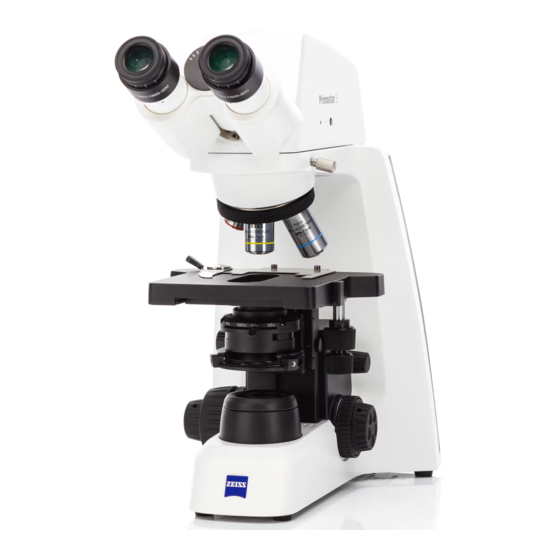
Related Manuals for Zeiss Primostar 3


Summary of Contents for Zeiss Primostar 3
- Page 1 Instruction Manual ZEISS Primostar 3 Upright Microscope for Education and Routine...
- Page 2 Effective from: 10/2020 © 2020 Without the prior written consent of ZEISS, this document or any part of it must neither be translated nor reproduced or transmitted in any form or by any means - including electronic or mechanic methods, by photocopying, recording or by any in- formation or filing system.
-
Page 3: Table Of Contents
Eyepiece....................31 3.2.8 Cable and Screw Tool Storage..............31 Accessories for Connecting the Microscope............32 Objective Labeling ....................33 On Screen Display (OSD) menu of the Primostar 3 HD IP Camera......35 3.5.1 Home Menu..................... 35 3.5.2 Settings Menu..................37 4 Installation...................... - Page 4 Connecting the Microscope to the Battery Supply Unit......58 4.4.3 Connecting the Microscope to a Power Bank ........... 59 Connecting the Primostar 3 HD IP Camera to a Storage Medium or Imaging De- vice ........................60 4.5.1 Connecting a USB Flash Drive..............60 4.5.2...
- Page 5 Applicable Standards and Regulations ..............97 Performance Data and Specifications..............97 Performance Data and Specifications of the Optional Components....... 99 Performance Data and Specifications of the Primostar 3 HD IP camera ....101 10 Accessories and Optional Components ..............103 10.1 Accessories......................
-
Page 6: General Information
ZEISS 1 General Information This Instruction Manual pertains to the Primostar 3, hereinafter referred to as the "microscope". This Instruction Manual contains basic steps and safety information that must be observed during operation and maintenance. For this reason, these operating instructions must be read by the spe- cialist staff / operator prior to commissioning and must always be available at the place of use of the microscope. -
Page 7: Further Applicable Documents
System and 3rd The Microscope can be configured in many ways. Information about the individual components, Party Components, enhancements and accessories can be obtained from your ZEISS Sales & Service Partner. Also refer Accessories to the 3rd Party documentation of the manufacturer. -
Page 8: Contact
1 General Information | 1.4 Contact ZEISS 1.4 Contact If you have any questions or problems, please contact your local ZEISS Sales & Service Partner or one of the following addresses: Headquarter Phone: +49 1803 33 63 34 Fax: +49 3641 64 3439 Email: info.microscopy.de@zeiss.com... -
Page 9: Safety
If it is noted that protection measures are no longer effective or other circumstances occur which impair safety and cause changes in operating behavior, the microscope should be shut down im- mediately and a ZEISS service technician should be notified. Make sure that all the protective pan- els and warning labels are attached and readable. -
Page 10: Requirements For Users
Detachable mains supply must not be replaced with inadequately rated cords. Always use the power cords supplied by ZEISS. When an unsuitable power cord is used, ZEISS can no longer guar- antee the electrical safety and functionality of the Microscope. -
Page 11: Warning And Information Labels
Only use microscope com- ponents supplied by ZEISS. Do not open the device unless you are trained and explicitly authorized by ZEISS. Always contact ZEISS or a certified service agency for the repair of the instrument. -
Page 12: Fig. 3 Positions Of Labels On The Fluorescence Unit
The meaning of each warning and information label is explained below. Posi- Symbol Description tion Hot surface below Operate microscope only on a stable, solid, smooth and not tinderlike (non-flammable) surface. Microscope type label Instruction Manual ZEISS Primostar 3 | en-US | Rev. 1 | 415501-7011-111_en... -
Page 13: Safety Devices And Interlocks
In case of damage or defect, the affected parts of the Microscope must be taken out of operation immediately and be secured against unintentional use. For verifying the safety of the Microscope, please contact your ZEISS service representative. Please keep the service logs and logbooks. -
Page 14: Safety Device Of The Reflected-Light Fluorescence Illuminator
To check the microscope safety, please contact your ZEISS sales and service partner and keep the service protocols for your microscope. -
Page 15: Product And Functional Description
3 Product and Functional Description | 3 Product and Functional Description The Primostar 3 are transmitted-light microscopes of compact design with a small footprint. The Microscope provide high resolution, infinity-corrected objectives for all important transmitted- light techniques, such as brightfield, darkfield, simple polarization, and phase contrast mi- croscopy. -
Page 16: Main Components Of The Imaging System
Abbe condenser 0.9/1.25 field 20, Condenser carrier, Fixed-Köhler Fixed-Köhler Luminous-field diaphragm, Fixed-Köhler Trinocular tube 25°/20 (50:50) Small hand lift Stand Specimen holder left for rackless stage Stage carrier Focusing drive Instruction Manual ZEISS Primostar 3 | en-US | Rev. 1 | 415501-7011-111_en... -
Page 17: Primostar 3 Iled (Fixed-Köhler)
Luminous-field diaphragm, Fixed-Köhler Binocular tube 25°/20 Reflected-light fluorescence illuminator Stand iLED Specimen holder left for rackless stage Stage carrier Focusing drive Instruction Manual ZEISS Primostar 3 | en-US | Rev. 1 | 415501-7011-111_en... -
Page 18: Primostar 3 (Fixed-Köhler) With Primostar 3 Hd Ip Camera
ZEISS 3.1.3 Primostar 3 (Fixed-Köhler) with Primostar 3 HD IP Camera The Fixed-Köhler microscope with Primostar 3 HD IP camera has the following main components: Fig. 7: Main components of Fixed-Köhler microscope with Primostar 3 HD IP camera Eyepiece WF 10x/20 Br. Foc. -
Page 19: Primostar 3 (Full-Köhler)
Abbe condenser 0.9/1.25 field 22, Full- Köhler Luminous-field diaphragm, Full-Köhler Trinocular tube 25°/22 (50:50) Stand Specimen holder for 2 sliders Stage carrier Focusing drive Transmitted-light illuminator, LED or Instruction Manual ZEISS Primostar 3 | en-US | Rev. 1 | 415501-7011-111_en... -
Page 20: Controls And Connections
Rotary knob to adjust the illumination stage intensity for transmitted light Control knob for X travel of rackless Coarse focusing drive (right side) stage Fine focusing drive (right side) Instruction Manual ZEISS Primostar 3 | en-US | Rev. 1 | 415501-7011-111_en... -
Page 21: Fig. 10 Stand Controls On The Left Side
Knurled ring for condenser height ad- Knurled ring for adjusting the smooth- justment ness of the coarse focusing drive Coarse focusing drive (left side) Fine focusing drive (left side) Instruction Manual ZEISS Primostar 3 | en-US | Rev. 1 | 415501-7011-111_en... -
Page 22: Fig. 11 Stand Controls And Connections On The Rear Side
(12 V) (e.g. for the battery supply unit) Info When the DC 5V switch is set to the position, the maximum output of the USB port is 1 A. Instruction Manual ZEISS Primostar 3 | en-US | Rev. 1 | 415501-7011-111_en... -
Page 23: Full-Köhler Stand
/ off the Light manager and the ECO mode Control knob for X travel of rackless Fine focusing drive (right side) stage Coarse focusing drive (right side) Instruction Manual ZEISS Primostar 3 | en-US | Rev. 1 | 415501-7011-111_en... -
Page 24: Fig. 13 Stand Controls On The Left Side
Knurled ring for adjusting the smooth- Coarse focusing drive (left side) ness of the coarse focusing drive Fine focusing drive (left side) Centering screw (knurled screw) for condenser on condenser carrier (left side) Instruction Manual ZEISS Primostar 3 | en-US | Rev. 1 | 415501-7011-111_en... -
Page 25: Fig. 14 Stand Controls And Connections On The Rear Side
The ECO mode can be disabled by triple clicking the intensity knob (for example in case of long time video shooting). You will see the Cyan LED belt illuminating once as a sign. Triple clicking the intensity knob again will reactivate ECO mode. Instruction Manual ZEISS Primostar 3 | en-US | Rev. 1 | 415501-7011-111_en... -
Page 26: Reflected-Light Fluorescence Illuminator Iled
Always turn the transmitted light/re- flected light changeover switch first up- ward and then to the desired position. Using force to turn it downward will damage the reflected-light illuminator. Instruction Manual ZEISS Primostar 3 | en-US | Rev. 1 | 415501-7011-111_en... -
Page 27: Primostar 3 Hd Ip Camera
3.2.4 Primostar 3 HD IP Camera Purpose The Primostar 3 HD IP camera is used to visualize and transfer the microscopic image to an exter- nal medium, such as a separate monitor, PC or tablet PC, via data line or Wi-Fi connection. -
Page 28: Fig. 18 Cover Plate (For Covering The Usb Type A Port And The Rj12 Port) Of The Primostar 3 Hd Ip Camera On The Rear Side
Tab. 4: System status/operating mode of the Primostar 3 HD IP camera shown by LED indicator Fig. 18: Cover plate (for covering the USB TYPE A port and the RJ12 port) of the Primostar 3 HD IP camera on the rear side... -
Page 29: Battery Supply Unit
For covering the USB TYPE A port and the RJ12 port Function The visualized images of the Primostar 3 HD IP camera may only be used for training and re- search. Info Direct generation of diagnostic results from these images is not recommended. -
Page 30: Condenser
Dovetail ring mount Front lens Turret condenser Display field for selected contrast stop Turret disk with five positions for: Phase ring adjustment holes Brightfield Phase contrast Ph1, Ph2, Darkfield Instruction Manual ZEISS Primostar 3 | en-US | Rev. 1 | 415501-7011-111_en... -
Page 31: Eyepiece
If iLED module is used, the 3M Allen wrench can be stored on its rear side. Fig. 23: Storage places Holder for power cable Storage place for phase plate adjust- ment tool Instruction Manual ZEISS Primostar 3 | en-US | Rev. 1 | 415501-7011-111_en... -
Page 32: Accessories For Connecting The Microscope
(not supplied) menu Keyboard For typing in the menu (not supplied) USB Wi-Fi adapter (has to Connection between the camera and be ordered separately) a network or iPad Instruction Manual ZEISS Primostar 3 | en-US | Rev. 1 | 415501-7011-111_en... -
Page 33: Objective Labeling
- above that limit no additional resolution is provided. Infinitive mechanical tube ∞ The objective can be used with tubes of any length. length Instruction Manual ZEISS Primostar 3 | en-US | Rev. 1 | 415501-7011-111_en... -
Page 34: Tab. 6 Obligatory Label Components
Info Due to their short working distance, the following objectives have a resilient mount (specimen protection): 20x/Ph 2 40x/Ph 2 100x dry objective 100x/Ph 3 oil 100x oil Instruction Manual ZEISS Primostar 3 | en-US | Rev. 1 | 415501-7011-111_en... -
Page 35: On Screen Display (Osd) Menu Of The Primostar 3 Hd Ip Camera
3 Product and Functional Description | 3.5 On Screen Display (OSD) menu of the Primostar 3 HD IP ZEISS Camera 3.5 On Screen Display (OSD) menu of the Primostar 3 HD IP Camera When the Primostar 3 HD IP camera is powered and connected to a display device via HDMI, the OSD menu will be shown automatically on the connected display device. - Page 36 3 Product and Functional Description | 3.5 On Screen Display (OSD) menu of the Primostar 3 HD IP Cam- ZEISS Target Intensity controls Auto White Balance button Auto Exposure mode, the light in- Ensures a consistent color temperature tensity can be fine-tuned using the of the image by continuously calculat- slider or the input field.
-
Page 37: Settings Menu
3 Product and Functional Description | 3.5 On Screen Display (OSD) menu of the Primostar 3 HD IP ZEISS Camera 3.5.2 Settings Menu Fig. 25: Settings menu, control elements Image Settings icon Microscope System Settings icon Opens the Image Settings menu. -
Page 38: Fig. 26 Image Settings Menu, Control Elements
3 Product and Functional Description | 3.5 On Screen Display (OSD) menu of the Primostar 3 HD IP Cam- ZEISS 3.5.2.1 Image Settings Menu Fig. 26: Image Settings menu, control elements Gamma controls Optimize Denoise button Enable you to adjust the gamma value. -
Page 39: Fig. 27 Microscope System Menu, Control Elements
3 Product and Functional Description | 3.5 On Screen Display (OSD) menu of the Primostar 3 HD IP ZEISS Camera 3.5.2.2 Microscope System Menu Fig. 27: Microscope system menu, control elements Objectives button (only for Full-Köhler Shading Correction button stands) Opens a menu to define the shading... -
Page 40: Fig. 28 Operating System Menu, Control Elements
3 Product and Functional Description | 3.5 On Screen Display (OSD) menu of the Primostar 3 HD IP Cam- ZEISS 3.5.2.3 Operating System Menu Operating System menu provides options such as setting the language, defining the file- name format, and updating the system firmware. -
Page 41: Fig. 29 File Options Menu, Control Elements
3 Product and Functional Description | 3.5 On Screen Display (OSD) menu of the Primostar 3 HD IP ZEISS Camera 3.5.2.3.1 File Options Menu Fig. 29: File Options menu, control elements Filename format example Filename format components Shows the template of the filenames... -
Page 42: Installation
4 Installation Perform only the installation work described in this document. All other installation work not de- scribed below may only be carried out by an authorized ZEISS service representative. 4.1 Safety during Installation Before installing and starting up the microscope, be sure to carefully read and observe the notes on instrument safety, see Safety [ 9]. -
Page 43: Installing Additional Components
5. To detach the tube, loosen the knurled clamping screw. 6. Turn the installed tube clockwise by approximately 90° and detach it on the right side up- ward. Instruction Manual ZEISS Primostar 3 | en-US | Rev. 1 | 415501-7011-111_en... -
Page 44: Installing The Reflected-Light Fluorescence Illuminator Iled Onto The Stand
RJ12 cable is available. Procedure 1. Insert the reflected-light illuminator at correct angle and slightly inclined with its dovetail mount into the stand. 2. Position the reflected-light illuminator horizon- tally. Instruction Manual ZEISS Primostar 3 | en-US | Rev. 1 | 415501-7011-111_en... - Page 45 4. Plug the RJ12 cable into the RJ12 female con- nector port of the stand. 5. Align the reflected-light illuminator to the outer edges of the stand. 6. Tighten the set screw of the stand. Instruction Manual ZEISS Primostar 3 | en-US | Rev. 1 | 415501-7011-111_en...
- Page 46 For this reason, spectacle wearers should use the standard eyecups. Info For mounting reflected-light fluorescence illuminator iLED on stands with small hand lift, please contact an authorized ZEISS service representative. Instruction Manual ZEISS Primostar 3 | en-US | Rev. 1 | 415501-7011-111_en...
-
Page 47: Attaching Or Removing Yellow Filter Or Tl Cover Plate (Fixed Köhler Stand)
3. Re-attach the cover cap to the luminous-field diaphragm and lock it. 4. If required, place the TL cover plate into the Abbe condenser phase plate slot. Instruction Manual ZEISS Primostar 3 | en-US | Rev. 1 | 415501-7011-111_en... -
Page 48: Inserting Color Filters (Full Köhler Stand)
3. Put the desired filter − yellow, green or blue − onto the mounting surface of the luminous- field diaphragm. 4. Screw the cover cap back into place. Instruction Manual ZEISS Primostar 3 | en-US | Rev. 1 | 415501-7011-111_en... -
Page 49: Installing The Polarizer Plate (Full Köhler Stand)
2. Place the analyzer plate into the beam path on the top on stand. à The position stop on the analyzer plate has to match with the position stop on the stand. 3. Re-attach the tube on the stand. Instruction Manual ZEISS Primostar 3 | en-US | Rev. 1 | 415501-7011-111_en... -
Page 50: Installing The Primostar 3 Hd Ip Camera
If needed, mount the reflected-light fluorescence illuminator iLED onto the stand first, see In- stalling the Reflected-light Fluorescence Illuminator iLED onto the Stand [ 44]. Then, mount the Primostar 3 HD IP camera onto the reflected-light fluorescence illuminator iLED in the same way as described below. Procedure 1. - Page 51 RJ12 female connector port of the reflected- light fluorescence illuminator iLED. 7. Align the Primostar 3 HD IP camera to the outer edges of the stand. 8. Tighten the set screw of the stand. Instruction Manual ZEISS Primostar 3 | en-US | Rev. 1 | 415501-7011-111_en...
-
Page 52: Installing A Camera To The Trinocular Tube
A camera adapter P95-C 2/3" 0.65x or P95-C 1/2" 0.5x Procedure 1. Loosen the clamping screw and remove the dust cap from the tube. 2. Mount the C-mount camera adapter on the camera. Instruction Manual ZEISS Primostar 3 | en-US | Rev. 1 | 415501-7011-111_en... -
Page 53: Replacing Objectives
5. If you intend to insert the objective in a previously unused lens mount, remove the dust cover from the corresponding mount of the nosepiece. Instruction Manual ZEISS Primostar 3 | en-US | Rev. 1 | 415501-7011-111_en... -
Page 54: Installing/Removing The Condenser
4. Remove the installed condenser, e.g. Abbe condenser. 5. Insert the condenser to be installed, e.g. turret condenser, with its dovetail ring mount into the condenser carrier. 6. Fix it by tightening the clamping screw. Instruction Manual ZEISS Primostar 3 | en-US | Rev. 1 | 415501-7011-111_en... -
Page 55: Installing/Removing The Mirror
4.3.12 Inserting an Eyepiece Pointer or an Eyepiece Micrometer Hex Key, 1.0 mm Parts and Tools Procedure 1. Use an Allen wrench to loosen the set screw on the binocular body from below. Instruction Manual ZEISS Primostar 3 | en-US | Rev. 1 | 415501-7011-111_en... - Page 56 4. Insert the eyepiece pointer or the eyepiece mi- crometer into the eyepiece (with the coated side facing your eyes). 5. Screw in the eyepiece stop again. 6. Insert the eyepiece into the tube. Instruction Manual ZEISS Primostar 3 | en-US | Rev. 1 | 415501-7011-111_en...
-
Page 57: Folding Over The Eyecups
4.3.14 Changing the Eyecups Procedure 1. Remove the existing eyecup from the eyepiece, e.g. the foldover rubber eyecups. 2. Attach the desired eyecups, e.g. the special eyecups with light protection. Instruction Manual ZEISS Primostar 3 | en-US | Rev. 1 | 415501-7011-111_en... -
Page 58: Connecting The Microscope To The Power Supply
Fig. 31: Connecting the microscope to the battery supply unit 2. Make sure the DC 5V switch is in the position. Instruction Manual ZEISS Primostar 3 | en-US | Rev. 1 | 415501-7011-111_en... -
Page 59: Connecting The Microscope To A Power Bank
2. Switch the DC 5V switch to the position. 3. Plug the other side of the USB Type A to A cable into the appropriate port of the power bank Instruction Manual ZEISS Primostar 3 | en-US | Rev. 1 | 415501-7011-111_en... -
Page 60: Connecting The Primostar 3 Hd Ip Camera To A Storage Medium Or Imaging Device
Procedure 1. Insert the flash drive into one of the USB Type A ports of the Primostar 3 HD IP camera. Info To view the captured images or videos connect the USB flash drive to a PC or laptop. -
Page 61: Connecting To A Display (Without Pc)
ZEISS 4 Installation | 4.5 Connecting the Primostar 3 HD IP Camera to a Storage Medium or Imaging Device 4.5.3 Connecting to a Display (without PC) The Primostar 3 HD IP camera can be connected to a monitor, TV or projector for visualization of the live image data and for operating the On Screen Display menu (OSD) functions. - Page 62 4.5.4.1 Connecting the Camera via Ethernet Procedure 1. Insert the Ethernet cable into the jack on the reverse side of the Primostar 3 HD IP camera. 2. Insert the Ethernet cable's opposite connector into the corresponding socket on your WLAN router.
- Page 63 ZEISS 4 Installation | 4.5 Connecting the Primostar 3 HD IP Camera to a Storage Medium or Imaging Device 4.5.4.2 Connecting the Camera via Wi-Fi Adapter Procedure 1. Unscrew the plastic cover plate. 2. Insert the Wi-Fi adapter into the USB type A port.
-
Page 64: Installing Software For Use Of The Primostar 3 Hd Ip Camera
4 Installation | 4.6 Installing Software for Use of the Primostar 3 HD IP Camera ZEISS 4.6 Installing Software for Use of the Primostar 3 HD IP Camera To capture images with the Primostar 3 HD IP camera tube to a PC or iPad, you have the follow- ing options: §... -
Page 65: First Operating Steps
Procedure 1. Ensure the DC 5V switch is in the position. à DC 5V switch is only available on Fixed- Köhler stands. 2. Switch on the main power ON/OFF button. Instruction Manual ZEISS Primostar 3 | en-US | Rev. 1 | 415501-7011-111_en... -
Page 66: Microscope Is Connected To The External Dc Power Supply (12 V)
3. Switch on the main power ON/OFF button. Info When the DC 5V switch is set to the position, the maximum output of the USB port is 1 A. Instruction Manual ZEISS Primostar 3 | en-US | Rev. 1 | 415501-7011-111_en... -
Page 67: Microscope Is Connected To A Power Bank
The adjustment of the interpupillary distance is correct when you see only one round image while looking through the two eyepieces. Procedure 1. Rotate the eyepiece tubes symmetrically to- ward or away from one another. Instruction Manual ZEISS Primostar 3 | en-US | Rev. 1 | 415501-7011-111_en... -
Page 68: Setting The Viewing Height
4. Look at the specimen through the eyepiece with the eyepiece pointer or micrometer. 5. Use the focus drive to bring the microscopic image into focus until both the microscopic im- age and the eyepiece pointer are sharply de- fined. Instruction Manual ZEISS Primostar 3 | en-US | Rev. 1 | 415501-7011-111_en... -
Page 69: Adjusting The Transmitted-Light Brightfield On The Full-Köhler Microscope
A 10x objective for use with cover glass of 0.17 mm thickness is mounted. Procedure 1. Rotate the 10x objective into the light path us- ing the knurled ring of the nosepiece. Instruction Manual ZEISS Primostar 3 | en-US | Rev. 1 | 415501-7011-111_en... - Page 70 Brightfield (turn the switch fully upward first). 6. Use the rotary knob for illumination intensity to adjust the illumination to a comfortable setting. Instruction Manual ZEISS Primostar 3 | en-US | Rev. 1 | 415501-7011-111_en...
- Page 71 à The image of the high-contrast specimen is sharp for both eyes. 11. Close the luminous-field diaphragm until its edges become visible in the field of view. Instruction Manual ZEISS Primostar 3 | en-US | Rev. 1 | 415501-7011-111_en...
- Page 72 The size of the field of view and the objective aperture change with every objective change. Therefore, the adjustment of the luminous-field diaphragm and the aperture diaphragm ac- cording to Köhler has to be repeated to obtain optimum microscopy conditions. Instruction Manual ZEISS Primostar 3 | en-US | Rev. 1 | 415501-7011-111_en...
-
Page 73: Adjusting The Transmitted-Light Brightfield On The Fixed-Köhler Microscope
4. Push the slider containing the yellow filter with its filter position into the light path. 5. Adjust to the desired magnification by rotating the corresponding objective into the light path. Instruction Manual ZEISS Primostar 3 | en-US | Rev. 1 | 415501-7011-111_en... -
Page 74: Adjusting The Transmitted-Light Phase Contrast Or The Transmitted-Light Darkfield Using A Contrast Slider
2 x Hex key, 1.5 mm Parts and Tools Prerequisite The phase contrast method on the microscope requires a stand with Full-Köhler equipment. ü ü Contrast slider for phase contrast or darkfield. Instruction Manual ZEISS Primostar 3 | en-US | Rev. 1 | 415501-7011-111_en... - Page 75 (fitting the objective used, Push the phase contrast slider from the left into the Abbe condenser until it reaches the lock-in position. 6. Screw the locking screw into the contrast slider. Instruction Manual ZEISS Primostar 3 | en-US | Rev. 1 | 415501-7011-111_en...
- Page 76 11. Center the phase stop from position position by turning the two adjusting screws of the slider using the two Allen wrenches. 12. Afterwards, replace the diopter or telescope with the eyepiece again. Instruction Manual ZEISS Primostar 3 | en-US | Rev. 1 | 415501-7011-111_en...
- Page 77 5 First Operating Steps | 5.6 Adjusting the Transmitted-Light Phase Contrast or the Transmitted-Light ZEISS Darkfield using a Contrast Slider Info For darkfield application, use the darkfield slider instead of the phase contrast slider. Instruction Manual ZEISS Primostar 3 | en-US | Rev. 1 | 415501-7011-111_en...
-
Page 78: Adjusting The Transmitted-Light Phase Contrast Or The Transmitted-Light Darkfield Using The Turret Condenser
3. Open the luminous-field diaphragm on the stand. 4. Turn the turret disk of the turret condenser to the phase contrast position (Ph 1 Ph 2 Ph 3) that corresponds to the objective being used. Instruction Manual ZEISS Primostar 3 | en-US | Rev. 1 | 415501-7011-111_en... - Page 79 For darkfield application, use the darkfield position of the turret condenser instead of the phase contrast position. Info If the turret condenser is not equipped with a darkfield stop, contact an authorized ZEISS ser- vice technician for installation. Instruction Manual ZEISS Primostar 3 | en-US | Rev. 1 | 415501-7011-111_en...
-
Page 80: Adjusting The Transmitted-Light Simple Polarization Contrast
1. Adjust the microscope as you would for transmitted-light brightfield, see Adjusting the Transmitted-Light Brightfield on the Full-Köhler Microscope [ 69]. 2. Turn the nosepiece to move the objective for fluorescence application into the light path (e.g. objective 40x). Instruction Manual ZEISS Primostar 3 | en-US | Rev. 1 | 415501-7011-111_en... - Page 81 The pilot lamp at the front of the reflected-light illuminator is blue. The brightness of the pilot lamp corresponds to the illumination intensity adjusted for reflected light. 5. Focus on the specimen using the focusing drive. Instruction Manual ZEISS Primostar 3 | en-US | Rev. 1 | 415501-7011-111_en...
-
Page 82: Capturing Images And Videos Using The Integrated Smart 8 Mp Color Camera
4. To stop video recording briefly press the Snap button on the camera again. à The video is saved to the USB flash drive in MP4 format. Instruction Manual ZEISS Primostar 3 | en-US | Rev. 1 | 415501-7011-111_en... -
Page 83: Basic Procedure Using Osd Menu
Settings menu on your iPad or PC. Info For further support in using Labscope Lite, see www.zeiss.com/microscopy/commu- nity. Please check the Labscope, ZEN Lite threads for problem-solving notes. Instruction Manual ZEISS Primostar 3 | en-US | Rev. 1 | 415501-7011-111_en... -
Page 84: Switching Off The Microscope
1. After finishing work, switch off the microscope at the main power ON/OFF button. 2. If connected, switch off the power bank. 3. Cover the microscope with the dust cover. Instruction Manual ZEISS Primostar 3 | en-US | Rev. 1 | 415501-7011-111_en... -
Page 85: Care And Maintenance
Only perform preventive measures as described in the document. All maintenance, service and re- pair work not described above may only be performed by an authorized ZEISS service technician. Unauthorized interference with the microscope or improper use may result in personal injury or property damage and void any warranty. -
Page 86: Maintenance Work
6.3 Maintenance Work Only conduct maintenance work described in this document. All pursuing tasks of maintenance, service and repair not described here must only be performed by an authorized ZEISS service rep- resentative. 6.3.1 Replacing the 6 V/30 W Halogen Lamp of the Halogen Module... -
Page 87: Replacing The Batteries Of The Battery Supply Unit
NiCd or NiMH, 1.2 V, with a capacity of 5000 mAh (min.) to 9000 mAh (max.), 4. Pay attention to the correct polarity (see markings in the battery compartments). Instruction Manual ZEISS Primostar 3 | en-US | Rev. 1 | 415501-7011-111_en... -
Page 88: Charging The Batteries Of The Battery Supply Unit
2. If required, disconnect the battery supply unit from the mains power supply. Instruction Manual ZEISS Primostar 3 | en-US | Rev. 1 | 415501-7011-111_en... -
Page 89: Firmware Update Of The Primostar 3 Hd Ip Camera
1. Download the latest firmware from the website. 2. Save the update file to the root folder of the USB flash drive. 3. Insert the flash drive into the Primostar 3 HD IP camera's USB port or a connected USB hub. 4. In the menu, click Settings >... -
Page 90: Cleaning The Primostar 3 Hd Ip Camera
1. The filter glass may only be cleaned with a suitable agent. 2. Remove dust from the filter glass with an optical brush, blower brush, cotton swab, optical paper or lint-free cotton cloth. Instruction Manual ZEISS Primostar 3 | en-US | Rev. 1 | 415501-7011-111_en... -
Page 91: Troubleshooting
6 V/30 W halogen lamp or LED Replace the defective 6 V/30 though the microscope source is defective. W halogen lamp or the LED has been switched on. module. Instruction Manual ZEISS Primostar 3 | en-US | Rev. 1 | 415501-7011-111_en... -
Page 92: Tab. 10 Troubleshooting On The Microscope
Unsing the control knob, move the specimen holder to the left and right until it hits the end stop. The stage travel range is reset. Tab. 10: Troubleshooting on the microscope Instruction Manual ZEISS Primostar 3 | en-US | Rev. 1 | 415501-7011-111_en... -
Page 93: Troubleshooting Primostar 3 Hd Ip Camera
Settings are not stored. It takes 5 seconds for the set- settings (e.g. manual tings to be automatically white balance, HDMI res- stored. olution) if the power sup- ply is disrupted. Instruction Manual ZEISS Primostar 3 | en-US | Rev. 1 | 415501-7011-111_en... -
Page 94: Tab. 11 Troubleshooting On The Primostar 3 Hd Ip Camera
Press factory reset button on pected behavior. been changed unintentionally. the camera, see Primostar 3 HD IP Camera [ 27]. Tab. 11: Troubleshooting on the Primostar 3 HD IP camera Instruction Manual ZEISS Primostar 3 | en-US | Rev. 1 | 415501-7011-111_en... -
Page 95: Troubleshooting With Zen Lite Software
Connect the Primostar 3 HD IP camera to the PC with the USB 3.0 cable and re-start the cam- era. Tab. 12: Troubleshooting on using the ZEN lite software Instruction Manual ZEISS Primostar 3 | en-US | Rev. 1 | 415501-7011-111_en... -
Page 96: Transport And Storage
Permissible air humidity (without condensa- max. 93 % at 40 °C tion) Transport in Parameter Value packaging Permissible ambient temperature -40 to +70 °C Permissible air humidity (without condensa- max. 93 % at 40 °C tion) Instruction Manual ZEISS Primostar 3 | en-US | Rev. 1 | 415501-7011-111_en... -
Page 97: Technical Data And Conformity
Microscope and the ability to achieve the specified perfor- mance with particular regard to long term and sensitive workflows as well as equipment safety. A site survey can be requested from your local ZEISS service representative prior to the installation. Location... - Page 98 In accordance with EN 55011 Class B (without Primostar 3 HD IP camera) Suppression of interference In accordance with EN 55011 Class A (with Primostar 3 HD IP camera) Instruction Manual ZEISS Primostar 3 | en-US | Rev. 1 | 415501-7011-111_en...
-
Page 99: Performance Data And Specifications Of The Optional Components
Fine focusing drive 0.5 mm / rev. Total stage lift 15 mm Nosepiece Feature Value Objective change manual via quadruple objective nosepiece Objectives infinity-corrected objective range Mounting thread W 0.8 Instruction Manual ZEISS Primostar 3 | en-US | Rev. 1 | 415501-7011-111_en... - Page 100 Small binocular Feature Value tube 25°/20 Maximum field-of-view number Interpupillary distance adjustable from 48 to 75 mm Tube angle 25° Viewing height 380 to 415 mm Viewing port, tube factor Instruction Manual ZEISS Primostar 3 | en-US | Rev. 1 | 415501-7011-111_en...
-
Page 101: Performance Data And Specifications Of The Primostar 3 Hd Ip Camera
9 Technical Data and Conformity | 9.4 Performance Data and Specifications of the Primostar 3 HD IP ZEISS camera Small binocular Feature Value phototube 25°/20 Maximum field-of-view number Interpupillary distance adjustable from 48 to 75 mm Tube angle 25° Viewing height 380 to 415 mm... - Page 102 9 Technical Data and Conformity | 9.4 Performance Data and Specifications of the Primostar 3 HD IP camera ZEISS Binocular tube Parameter Value 25°/22 Maximum field-of-view number (eyepiece) Acquired visual field of the camera 14.2 x 8.0 mm 16.3 mm (diagonal) Eyepiece (interpupillary) distance adjustable from 48 to 75 mm...
-
Page 103: Accessories And Optional Components
10x adjustable eyepieces for field-of-view numbers 20 or 22, suitable for spectacle wearers Info Additional information and detailed descriptions are available in the further applicable docu- ments, or ask your ZEISS Sales & Service Partner. Instruction Manual ZEISS Primostar 3 | en-US | Rev. 1 | 415501-7011-111_en... -
Page 104: Optional Components
Polarizer f/Primostar 3 415501-1805-000 Analyzer f/Primostar 3 415501-1806-000 Accessories for Component Cat. No. darkfield Slider DF f/Primostar 3 415500-1802-000 Filter Component Cat. No. Set of color filters blu/grn/yel d45x1.5 415500-1804-000 Instruction Manual ZEISS Primostar 3 | en-US | Rev. 1 | 415501-7011-111_en... - Page 105 Transmitted-light illumination 6V/30W 415501-1201-000 Transmitted-light mirror 415500-1202-000 Note: Attachable mirror can only be used with Primostar microscope, fixed-Köhler Illuminator spare Component Cat. No. part Bulb HAL 6V/30W f/Primostar 3 415500-1901-000 Instruction Manual ZEISS Primostar 3 | en-US | Rev. 1 | 415501-7011-111_en...
- Page 106 Dimension: L 430mm x W 280mm x H 500mm Transport+storage case f/Primostar 3 415501-1831-000 Info Additional information and detailed descriptions are available in the further applicable docu- ments, or ask your ZEISS Sales & Service Partner. Instruction Manual ZEISS Primostar 3 | en-US | Rev. 1 | 415501-7011-111_en...
- Page 107 Cover plate (for covering the USB TYPE A port and the RJ12 port) of the Primostar 3 HD IP camera on the rear side ................Fig. 19 Connections and special components of the Primostar 3 HD IP camera on the rear side ........................Fig. 20 Controls, indicator lights and connection on the battery supply unit.......
- Page 108 Tab. 2 Link types....................... Tab. 3 List of attached warning and information labels ............. Tab. 4 System status/operating mode of the Primostar 3 HD IP camera shown by LED in- dicator ........................Tab. 5 Connecting cables and accessories ................. Tab. 6 Obligatory label components..................
-
Page 109: Glossary
User Person examining a sample under the mi- croscope. Wi-Fi Wireless Fidelity Instruction Manual ZEISS Primostar 3 | en-US | Rev. 1 | 415501-7011-111_enInstruction Manual... -
Page 110: Index
Reflected-light fluorescence illuminator 26 Tube 43 Intended use 9 Interpupillary distance 67 Darkfield 75, 78 Labscope 64, 83 LED illumination 103 EMC requirements 98 Location requirements 97 Ethernet 62 Eyecup 57 Instruction Manual ZEISS Primostar 3 | en-US | Rev. 1 | 415501-7011-111_en... - Page 111 Settings menu 37 Software 7, 64 Standards 97 Storage 96 Switching off 84 Switching on 65, 66, 67 Tool storage 31 Training 10 Transmitted-light brightfield 69, 73 Instruction Manual ZEISS Primostar 3 | en-US | Rev. 1 | 415501-7011-111_enInstruction Manual...
- Page 112 Carl Zeiss Microscopy GmbH Carl-Zeiss-Promenade 10 phone: +49 1803 33 63 34 07745 Jena fax: +49 3641 64 3439 Germany info.microscopy.de@zeiss.com www.zeiss.com/microscopy...