American Dynamics SpeedDome Ultra 8 Installation And Service Manual
Camera dome
Hide thumbs
Also See for SpeedDome Ultra 8:
- Operator's manual (144 pages) ,
- Installation and service manual (72 pages) ,
- Configuration and user's manual (46 pages)
Table of Contents
Advertisement
SpeedDome
Camera Dome
Installation and Service Guide
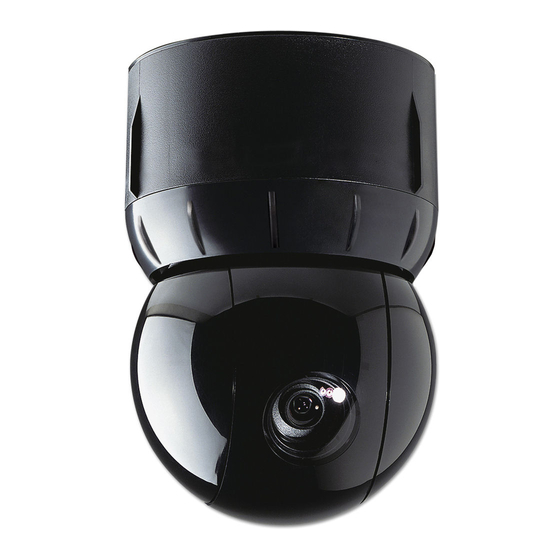
Figure 1. SpeedDome Ultra Camera Dome
Mounting
Base
Housing
Eyeball
Camera Dome Product Codes
Product
Description
ADSDU822N
22X, N, VERSION 1.00, BLACK
ADSDU822P
22X, P, VERSION 1.00, BLACK
ADSDU822WN
22X, N, VERSION 1.00, WHITE
ADSDU822WP
22X, P, VERSION 1.00, WHITE
ADSDU835N
35X, N, DAY/NIGHT, VERSION 1.00, BLACK
ADSDU835P
35X, P, DAY/NIGHT, VERSION 1.00, BLACK
ADSDU835WN
35X, N, DAY/NIGHT, VERSION 1.00, WHITE
ADSDU835WP
35X, P, DAY/NIGHT, VERSION 1.00, WHITE
© 2007 Sensormatic Electronics Corp.
SPEEDDOME ULTRA 8 CAMERA DOME
INSTALLATION AND SERVICE GUIDE
®
Ultra 8
Contents
About this Guide ....................................................1
About the Camera Dome .......................................2
Cable Requirements ..............................................7
Power-Up Routine..................................................8
Synchronizing Domes............................................8
Diagnostic LEDs ....................................................8
Warnings and Cautions .........................................9
Indoor Installation.................................................10
Using the Install/Removal Tool ............................14
Troubleshooting Indoor Domes ...........................16
Parts List for Authorized Users ............................25
Specifications-Indoor Dome.................................27
Declarations .........................................................29
Appendix A: Vicon Wiring Configurations ..........30
About this Guide
This guide explains how to connect the camera
dome to a mounting base and how to service it.
It does not explain how to:
• Determine a mounting location for the camera
dome. The mounting location is determined by
customer requirements; therefore, this
information is provided separately.
• Attach the mounting base. See information
shipped with the base.
• Assemble housings and structures used with
this camera dome. See information shipped with
the housing and structure.
• Program the camera dome. See operator's
guide shipped with the dome.
1 of 30
8200-0600-03, REV. B
Advertisement
Table of Contents
Troubleshooting

Related Manuals for American Dynamics SpeedDome Ultra 8


Summary of Contents for American Dynamics SpeedDome Ultra 8
-
Page 1: Table Of Contents
ADSDU835WN 35X, N, DAY/NIGHT, VERSION 1.00, WHITE ADSDU835WP 35X, P, DAY/NIGHT, VERSION 1.00, WHITE © 2007 Sensormatic Electronics Corp. SPEEDDOME ULTRA 8 CAMERA DOME INSTALLATION AND SERVICE GUIDE Contents About this Guide ...1 About the Camera Dome ...2 Cable Requirements ...7 Install/Removal Tool for Base with I/O Board...8... -
Page 2: About The Camera Dome
About the Camera Dome The SpeedDome Ultra 8 camera dome (Figure 1): • Mounts indoors, or outdoors (with accessory outdoor enclosure) • Communicates with the video controller over a SensorNet 485, RS-422, Manchester, or UTC (up-the-coax) network • Consists of a mounting base, housing, and rotating eyeball assembly. - Page 3 * Option in white, but can be painted to match decor. † Top hat housing/dome assembly also mounts to structure. SPEEDDOME ULTRA 8 CAMERA DOME INSTALLATION AND SERVICE GUIDE Tile Ceilings RHIUFB Fixed bracket.
- Page 4 Figure 4. Indoor mounting structures (optional) RHIUFB, RHIUAB RHIUIBM (with options) ADSDUPIHC ADSDUPIHS ADSDUPIVRC RHIUTH ADSDUPIVRS Vandal-Resistant RD500A Bubble RHIUPNDT RHIU3X3 RHIU4X4 SPEEDDOME ULTRA 8 CAMERA DOME INSTALLATION AND SERVICE GUIDE RHIUHC RHIUTH ADSDUPIHC ADSDUPIHS ADSDUPIVRC ADSDUPIVRS RHIUTR RUCLR RUSLV RUSMK RUGLD 4 of 30...
- Page 5 Note: Do not use the I/O board (designed for indoor use) in place of the environmental board. Figure 5. AD outdoor housing (optional) SPEEDDOME ULTRA 8 CAMERA DOME INSTALLATION AND SERVICE GUIDE SpeedDome Housing Adapter Bracket (Optional)
- Page 6 Note: Housing is shown for reference only. RHOTR over roof mount comes with the ROENDC end cap (shown with RHOTRF bracket) RHOPN pendant mount SPEEDDOME ULTRA 8 CAMERA DOME INSTALLATION AND SERVICE GUIDE ROENDC end cap RHOWPA pole mount comes with the ROENDC...
-
Page 7: Cable Requirements
(such as a J-box) and the worst-case low line voltage. These lengths are for Sensormatic composite cables, which use 18 wires. SPEEDDOME ULTRA 8 CAMERA DOME INSTALLATION AND SERVICE GUIDE Note: Typically, distances are used that provide a 15% margin between nominal and low line conditions. -
Page 8: Speeddome ® Ultra
I/O board. Figure 8. RHIRT indoor install/removal tool RHIRT Removal Tool Telescopic Pole SPEEDDOME ULTRA 8 CAMERA DOME INSTALLATION AND SERVICE GUIDE Power-Up Routine After power is connected to the dome, the dome performs the following homing routine. -
Page 9: Warnings And Cautions
3.3 Amps, meeting section 2.11 of IEC950, and a maximum of 250VA available. SPEEDDOME ULTRA 8 CAMERA DOME INSTALLATION AND SERVICE GUIDE The power supply can be obtained through Sensormatic or through another source where the provider can furnish the verification. -
Page 10: Indoor Installation
• Install/Removal tool to attach and detach domes and bubbles without a ladder. • Base kit: ADSDUIOB (black) or ADSDUIOBW (white). • SpeedDome Ultra 8 housing and eyeball assembly, 0101-0150-xx. Other Preparations To ensure a smooth and successful installation, you must: •... - Page 11 Output 2 (40mA sync. max.) — Output 3 (40mA sync. max.) — Ground SPEEDDOME ULTRA 8 CAMERA DOME INSTALLATION AND SERVICE GUIDE 6. Connect the alarm input cable, if used, to the TB3 connector. 7. Connect power to the TB4 connector.
- Page 12 Green Green (CR13) (CR9) 11. Set the dome address (Figure 11). Figure 11. Setting address switches SPEEDDOME ULTRA 8 CAMERA DOME INSTALLATION AND SERVICE GUIDE Use the following addresses for the protocols shown: AD Manchester, Range: 001—064 PELCO "P," 4800 baud RS-422, Range: 001–099...
- Page 13 13. Wait a few seconds for dome to begin its homing routine. This routine indicates that the address was placed into the dome memory and that the dome is ready for programming. SPEEDDOME ULTRA 8 CAMERA DOME INSTALLATION AND SERVICE GUIDE Turn clockwise to latch 13 of 30 8200-0600-03, REV.
-
Page 14: Using The Install/Removal Tool
The T-lanyard will prevent the skirt or bubble from falling. SPEEDDOME ULTRA 8 CAMERA DOME INSTALLATION AND SERVICE GUIDE TO CONNECT DOME: 1. - Page 15 Figure 13. How to use the install/removal tool Skirt or Bubble Attachment/Detachment Snap tool into pole Attachment Dome Connection (Reverse the steps to disconnect) Line up SPEEDDOME ULTRA 8 CAMERA DOME INSTALLATION AND SERVICE GUIDE Catch notch and pull down Detachment Line up 15 of 30...
-
Page 16: Troubleshooting Indoor Domes
• Install/Removal tool to connect/disconnect dome to indoor bases with I/O boards, and to attach/detach skirts and bubbles—without a ladder. SPEEDDOME ULTRA 8 CAMERA DOME INSTALLATION AND SERVICE GUIDE Routine Troubleshooting Use this procedure if: • Dome does not respond to commands •... - Page 17 9, page 18. If so, replace the I/O board or contact your sales representative for repair instructions. SPEEDDOME ULTRA 8 CAMERA DOME INSTALLATION AND SERVICE GUIDE Figure 14. I/O board connector and jumper locations Twisted...
-
Page 18: Detailed Troubleshooting
(CR12) Green Green (CR13) (CR9) SPEEDDOME ULTRA 8 CAMERA DOME INSTALLATION AND SERVICE GUIDE 9. Check the spring finger connector on the I/O board by connecting a known good dome to the base to verify contact between the spring fingers and the CPU board (under cap). Does... -
Page 19: Disassembling The Dome
On the bottom of the power supply board, check that the optical sensor is functioning and plugged into connector P3 on the power supply board. SPEEDDOME ULTRA 8 CAMERA DOME INSTALLATION AND SERVICE GUIDE Disassembling the Dome CAUTION: Once disassembled, parts of dome housing and eyeball assembly are "extremely... - Page 20 3. Reverse the steps to reassemble. Figure 16. Removing the CPU board SPEEDDOME ULTRA 8 CAMERA DOME INSTALLATION AND SERVICE GUIDE Removing the P/S Board CAUTION: Electrostatic-sensitive device. Use a ground strap when handling power supply board.
- Page 21 Verify pan gear turns freely! Figure 18. Removing the pan motor b. Pull out a. Lift up SPEEDDOME ULTRA 8 CAMERA DOME INSTALLATION AND SERVICE GUIDE Removing the Slot Covers 1. Gently swivel eyeball to totally expose one of two slot covers (Figure 19).
- Page 22 2) carefully lift the camera out. Figure 21. Removing the camera 4. Reverse the steps to reassemble. Ensure ribbon cable pins are inserted "face down". SPEEDDOME ULTRA 8 CAMERA DOME INSTALLATION AND SERVICE GUIDE Detaching the Eyeball 1. Perform procedure "Removing the Slot Covers"...
- Page 23 5. Gently pry off the yoke bracket covering the camera/lens board to access the bearing assembly (Figure 25). Figure 25. Removing the yoke brackets SPEEDDOME ULTRA 8 CAMERA DOME INSTALLATION AND SERVICE GUIDE The following steps refer to Figure 26. 6. Access camera/lens board.
- Page 24 5. Gently pry off the yoke bracket covering the pan gear assembly to access the tilt cable assembly (Figure 28). Figure 28. Removing the yoke brackets SPEEDDOME ULTRA 8 CAMERA DOME INSTALLATION AND SERVICE GUIDE 6. Access the tilt motor. To do this, loosen the captive retaining screw holding the tilt cable assembly in place and gently remove the assembly.
-
Page 25: Parts List For Authorized Users
Optical Sensor Slip Ring Assy. Standoff, M3x16 LG SS (Qty. 3†) Housing Bearing Assy., Pan Gear Trim Ring SPEEDDOME ULTRA 8 CAMERA DOME INSTALLATION AND SERVICE GUIDE Eyeball Assembly Description Cable Assy., Tilt Tilt Motor Yoke, Camera Slot Cover (No Lens)* Camera/Lens PC Board Bearing Assy., Lens... - Page 26 Figure 30. Base, housing, and eyeball assembly * ADSDU8IOB/ ADSDU8IOBW Housing and Eyeball Assy., SpeedDome Ultra 8 (0101-0150-xx) 26-29 SPEEDDOME ULTRA 8 CAMERA DOME INSTALLATION AND SERVICE GUIDE Housing Assembly Base Assembly (0404-0306-01/-02 with I/O Board* 26 of 30 Eyeball Assy. (0404-0079-xx)
-
Page 27: Specifications-Indoor Dome
Video output ... Low capacitance Zener suppressor 6.5V, 1500W Power line... TVS rated at 60V, 1.5 joules, 250A 8/20µs impulse SPEEDDOME ULTRA 8 CAMERA DOME INSTALLATION AND SERVICE GUIDE RS-422...TVS rated at 9.8V/1A, Manchester/ SensorNet 485 ...Gas discharge tube rated Alarm input ...TVS rated at 9.8V/1A,... - Page 28 Digital zoom ...11X Zoom pause...33X default; 22X selectable Zoom stop... 44X, 66X, 88X (default), Zoom/Focus accuracy ... ±0.5% SPEEDDOME ULTRA 8 CAMERA DOME INSTALLATION AND SERVICE GUIDE 35X Day/Night Camera Type ... Interline transfer 1/4in CCD array Scanning area ... 3.2 (H) x 2.4 (V) mm Scanning system...
-
Page 29: Declarations
SPEEDDOME ULTRA 8 CAMERA DOME INSTALLATION AND SERVICE GUIDE Other Declarations Thank you for using American Dynamics products. We = Horizontal view (m) support our products through an extensive and worldwide network of dealers. The dealer, through whom you originally... -
Page 30: Appendix A: Vicon Wiring Configurations
Appendix A: Vicon Wiring Configurations In Vicon systems where domes support loop through, daisy chain the SpeedDome Ultra 8 domes off the last Vicon dome in the communications chain. Figure 31. SpeedDome Ultra 8 dome loop-through wiring from Vicon dome...