American Dynamics SpeedDome Ultra VII EIS Installation And Service Manual
Day/night camera dome
Hide thumbs
Also See for SpeedDome Ultra VII EIS:
- Installation and service manual (72 pages) ,
- Operator's manual supplement (15 pages)
Table of Contents
Advertisement
Quick Links
®
SpeedDome
Ultra VII EIS
Day/Night Camera Dome
Installation and Service Guide
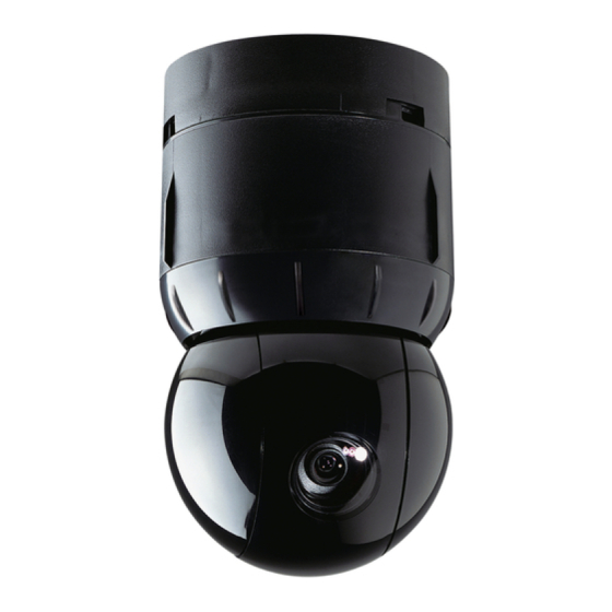
Figure 1. SpeedDome Ultra VII EIS Day/Night
Camera Dome
Mounting
Base
Housing
Eyeball
Camera Dome Product Codes
Product
Description
RAS918LS
DAY/NIGHT, EIS, 60HZ, 23X, NO BASE,
BLACK
RAS918LSP
DAY/NIGHT, EIS, 60HZ, 23X, STD BASE,
BLACK (RUPTB)
RAS918LSI
DAY/NIGHT, EIS, 60HZ, 23X, I/O BASE,
BLACK (RUIOB)
© 2005 Sensormatic Electronics Corp.
INSTALLATION AND SERVICE GUIDE
Contents
About this Guide ....................................................1
About the Camera Dome .......................................2
Cable Requirements ..............................................7
Power-Up Routine..................................................9
Synchronizing Domes............................................9
Diagnostic LEDs ....................................................9
Warnings and Cautions .........................................9
Indoor Installation.................................................11
Using the Install/Removal Tool ............................20
Troubleshooting Indoor Domes ...........................22
Parts List for Authorized Users ............................32
Specifications-Indoor Dome.................................34
Specifications-23X Camera with EIS ...................35
Declarations .........................................................36
Appendix A: Vicon Wiring Configurations............37
About this Guide
This guide explains how to connect the camera
dome to a mounting base and how to service it.
It does not explain how to:
• Determine a mounting location for the camera
dome. The mounting location is determined by
customer requirements; therefore, this
information is provided separately.
• Attach the mounting base. There are two types
of mounting bases. See information shipped
with the base.
• Assemble housings and structures used with
this camera dome. See information shipped with
the housing and structure.
• Program the camera dome. See operator's
guide shipped with the dome.
Page 1
Advertisement
Table of Contents
Troubleshooting

Related Manuals for American Dynamics SpeedDome Ultra VII EIS


Summary of Contents for American Dynamics SpeedDome Ultra VII EIS
-
Page 1: Table Of Contents
® SpeedDome Ultra VII EIS Day/Night Camera Dome Installation and Service Guide Figure 1. SpeedDome Ultra VII EIS Day/Night Camera Dome Mounting Base Housing Eyeball Camera Dome Product Codes Product Description RAS918LS DAY/NIGHT, EIS, 60HZ, 23X, NO BASE, BLACK RAS918LSP... -
Page 2: About The Camera Dome
About the Camera Dome The SpeedDome Ultra VII EIS day/night camera dome (Figure 1) comes in black, mounts indoors or outdoors (with accessory outdoor enclosure), and can communicate with the video controller over a SensorNet 485, RS-422, Manchester, or UTC (up- the-coax) network. - Page 3 Enables dome suspension from an I-beam. RHIUIBM version has all related accessories to suspend from I-beam, except 3.2cm (1 1/4in) NPT pipe. SPEEDDOME ULTRA VII EIS DAY/NIGHT CAMERA DOME INSTALLATION AND SERVICE GUIDE Electrical Box in Ceiling RHIU3X3 3 X 3 mounting plate Attaches dome to a standard 3.5 x 3.5 duplex electrical box.
- Page 4 Figure 4. Indoor mounting structures (optional) RHIUFB RHIUAB RHIUIBM ADSDUPIHC ADSDUPIHS ADSDUPIVRC ADSDUPIVRS Vandal Resistant Bubble RHIUPNDT RHIU3X3 RHIU4X4 SPEEDDOME ULTRA VII EIS DAY/NIGHT CAMERA DOME INSTALLATION AND SERVICE GUIDE RHIUHC RHIUTH RHIUTH RD500A RHIUTR RUCLR RUSLV RUSMK RUGLD 4 of 37 RHIU2X2...
- Page 5 Note: Do not use the I/O board (designed for indoor use) in place of the environmental board. Figure 5. RHODUL outdoor housing (optional) SPEEDDOME ULTRA VII EIS DAY/NIGHT CAMERA DOME INSTALLATION AND SERVICE GUIDE SpeedDome Housing Adapter Bracket (Optional)
- Page 6 Note: Housing is shown for reference only. RHOTR over roof mount comes with the ROENDC end cap (shown with RHOTRF bracket) RHOPN pendant mount SPEEDDOME ULTRA VII EIS DAY/NIGHT CAMERA DOME INSTALLATION AND SERVICE GUIDE ROENDC end cap RHOWPA pole mount comes with the ROENDC...
-
Page 7: Cable Requirements
These lengths are for Sensormatic composite cables, which use 18 ac power wires. SPEEDDOME ULTRA VII EIS DAY/NIGHT CAMERA DOME INSTALLATION AND SERVICE GUIDE Note: Typically, distances are used that provide a 15% margin between nominal and low line conditions. -
Page 8: Install/Removal Tool For Base With I/O Board
Dome or Fixed Camera Cat 2-6 UTP Cable Video Switcher/ Controller SPEEDDOME ULTRA VII EIS DAY/NIGHT CAMERA DOME INSTALLATION AND SERVICE GUIDE Install/Removal Tool for Base with I/O Board The install/removal tool (Figure 10) enables you to connect or disconnect the housing and eyeball... -
Page 9: Power-Up Routine
If an RS-422 network is used, other LEDs on the board indicate that wiring is correct, reversed, open, or grounded. SPEEDDOME ULTRA VII EIS DAY/NIGHT CAMERA DOME INSTALLATION AND SERVICE GUIDE Warnings and Cautions Please review the following warnings and cautions before you begin installation or service. - Page 10 (JW1), if the camera dome is connected at the end of a cable run or is connected to an I/O base. SPEEDDOME ULTRA VII EIS DAY/NIGHT CAMERA DOME INSTALLATION AND SERVICE GUIDE - When using the base without I/O board and...
-
Page 11: Indoor Installation
• Thoroughly review the project to ensure that all work meets or exceeds the above requirements. Bring alleged discrepancies to the attention of the CCTV Project Coordinator. SPEEDDOME ULTRA VII EIS DAY/NIGHT CAMERA DOME INSTALLATION AND SERVICE GUIDE Connecting to the Mounting Base without I/O Board... - Page 12 I/O Board Manufacturing Use, Range: 901—999 SPEEDDOME ULTRA VII EIS DAY/NIGHT CAMERA DOME INSTALLATION AND SERVICE GUIDE 2. Attach the safety lanyard to the cap on the housing and eyeball assembly (Figure 12). Use the M3x6 screw supplied with the lanyard.
- Page 13 3 first! a. Feed cables through the access hole in the base. SPEEDDOME ULTRA VII EIS DAY/NIGHT CAMERA DOME INSTALLATION AND SERVICE GUIDE b. Connect data and power wires to the 9-pin plug (refer to charts below).
- Page 14 LEDs CR2, CR3, and CR4 visible through opening. SPEEDDOME ULTRA VII EIS DAY/NIGHT CAMERA DOME INSTALLATION AND SERVICE GUIDE 7. Connect the housing and eyeball assembly to the base (Figure 15) by aligning the Cap and Base tabs and then turning clockwise until you hear a click.
- Page 15 Figure 16. Cable connections (Manchester requires separate cables for data and power) 9-pin plug LEDs CR2, CR3, and CR4 visible through opening. SPEEDDOME ULTRA VII EIS DAY/NIGHT CAMERA DOME INSTALLATION AND SERVICE GUIDE 4-pin plug 15 of 37 8200-0184-14, REV. A...
- Page 16 Blinking Blinking Steady, then Steady Blinking SPEEDDOME ULTRA VII EIS DAY/NIGHT CAMERA DOME INSTALLATION AND SERVICE GUIDE Possible Cause White (pin1) and black (pin 2) correctly wired. When the network has been detected. When data for this dome has been received. Thereafter, the yellow LED will flicker when data is sent to this dome.
- Page 17 Belden by calling 1-800-235-3361. Color Designation — Not used. Black Manchester (+) White Manchester (–) SPEEDDOME ULTRA VII EIS DAY/NIGHT CAMERA DOME INSTALLATION AND SERVICE GUIDE RS-422 data connections SensorNet data connections Setting Pins 1-2* Figure 17. Electrical connections 17 of 37...
- Page 18 Black 24 Vac Ground White 24 Vac SPEEDDOME ULTRA VII EIS DAY/NIGHT CAMERA DOME INSTALLATION AND SERVICE GUIDE 7. Reattach the I/O board. 8. Connect power to the base. 9. Check LEDs on the I/O board to verify power and data are reaching the dome (Figure 18).
- Page 19 (NTCIP), 9600 baud RS-422, Range: 401—499 Dept. of Transportation (NTCIP), 19.2K baud RS-422, Range: 501—599 SPEEDDOME ULTRA VII EIS DAY/NIGHT CAMERA DOME INSTALLATION AND SERVICE GUIDE PELCO "P," 2400 baud RS-422, Range: 601—699 PELCO "P," 9600 baud RS-422, Range: 701—799 Reset HITACHI VK-xxxx(E)R camera block from 38.4K to...
-
Page 20: Using The Install/Removal Tool
The T-lanyard will prevent the skirt or bubble from falling. SPEEDDOME ULTRA VII EIS DAY/NIGHT CAMERA DOME INSTALLATION AND SERVICE GUIDE TO CONNECT DOME: 1. - Page 21 Attachment Dome Connection (reverse steps to disconnect) Line up Do not use this tool to connect the base without I/O board! SPEEDDOME ULTRA VII EIS DAY/NIGHT CAMERA DOME INSTALLATION AND SERVICE GUIDE Catch notch and pull down Detachment...
-
Page 22: Troubleshooting Indoor Domes
• Install/Removal tool to connect/disconnect dome to indoor bases with I/O boards, and to attach/detach skirts and bubbles—without a ladder. SPEEDDOME ULTRA VII EIS DAY/NIGHT CAMERA DOME INSTALLATION AND SERVICE GUIDE Routine Troubleshooting Use this procedure if: • Dome does not respond to commands •... - Page 23 5. Verify coaxial video cable is securely connected to coax of I/O board (Figure 22). Is cable disconnected? YES Connect cable. Go to step 6. SPEEDDOME ULTRA VII EIS DAY/NIGHT CAMERA DOME INSTALLATION AND SERVICE GUIDE Figure 22. I/O board connector and jumper locations Pin 1...
- Page 24 Orange SensorNet 485 Yellow SensorNet 485 SPEEDDOME ULTRA VII EIS DAY/NIGHT CAMERA DOME INSTALLATION AND SERVICE GUIDE 8. If using RS-422 network and an I/O board is used, check comm. line connections by pressing and holding data test switch SW1 (Figure 23) and observing nearby red (CR34) and green (CR35) LEDs.
-
Page 25: Detailed Troubleshooting
• Dome contains electrostatic-sensitive PC boards. Use a ground strap when handling boards. SPEEDDOME ULTRA VII EIS DAY/NIGHT CAMERA DOME INSTALLATION AND SERVICE GUIDE Procedure 1. Match symptom to one of the following criteria: − Dome functions but does not pan −... -
Page 26: Disassembling The Dome
To order parts (authorized users only), see page 32. Tools Required • Phillips-head screwdriver. • Small slotted screwdriver. SPEEDDOME ULTRA VII EIS DAY/NIGHT CAMERA DOME INSTALLATION AND SERVICE GUIDE Removing the CPU Board CAUTION: Electrostatic-sensitive device. Use a ground strap when handling CPU board. - Page 27 Remove three standoffs, then remove power supply board from housing. 5. Reverse steps to reassemble. Figure 25. Removing the P/S board SPEEDDOME ULTRA VII EIS DAY/NIGHT CAMERA DOME INSTALLATION AND SERVICE GUIDE Removing the Pan Motor Referring to Figure 26.
- Page 28 4. Gently swivel eyeball to totally expose remaining slot cover. With other cover removed, this cover can be easily removed. Figure 27. Removing slot covers SPEEDDOME ULTRA VII EIS DAY/NIGHT CAMERA DOME INSTALLATION AND SERVICE GUIDE Removing the Camera 1. Perform procedure "Removing the Slot Covers"...
- Page 29 Figure 30. Loosening the eyeball 4. Detach slip ring connector (Figure 31). Figure 31. Detaching the eyeball SPEEDDOME ULTRA VII EIS DAY/NIGHT CAMERA DOME INSTALLATION AND SERVICE GUIDE Removing the Camera/Lens Board 1. Perform procedure "Removing the Slot Covers"...
- Page 30 Prongs (3) DO NOT unplug cable from J1. Camera/Lens Board Bearing Assembly SPEEDDOME ULTRA VII EIS DAY/NIGHT CAMERA DOME INSTALLATION AND SERVICE GUIDE Removing the Tilt Motor 1. Perform procedure "Removing the Slot Covers" (page28). 2. Perform procedure "Removing the Camera"...
- Page 31 CAUTION: When installing a new motor, be careful to properly mesh motor and tilt gears! Failure to do so can destroy both motor and tilt gear. Verify tilt gear turns freely! SPEEDDOME ULTRA VII EIS DAY/NIGHT CAMERA DOME INSTALLATION AND SERVICE GUIDE Updating/Reprogramming Dome Software...
-
Page 32: Parts List For Authorized Users
Pan Motor 3501-0017-01 Housing 0500-7255-02/-03 Bearing Assy., Pan 2510-0040-01 Gear Skirt 0500-6710-02 SPEEDDOME ULTRA VII EIS DAY/NIGHT CAMERA DOME INSTALLATION AND SERVICE GUIDE Eyeball Assembly Tilt Motor Slot Cover (No Lens)* Yoke, Camera Camera/Lens PC Board Bearing Assy., Lens Carriage Yoke Bracket (Qty. - Page 33 -11 Color 23X NTSC camera (BLK) -12 Color 23X PAL camera (BLK) -15 Color 23X NTSC camera (WHT) - 29 Color 23X NTSC EIS camera (BLK) SPEEDDOME ULTRA VII EIS DAY/NIGHT CAMERA DOME INSTALLATION AND SERVICE GUIDE Base Assembly Assembly*...
-
Page 34: Specifications-Indoor Dome
Data Storage ...128 Kbytes of SRAM Menu Languages ...English, French, German, Spanish, Italian, and Portuguese SPEEDDOME ULTRA VII EIS DAY/NIGHT CAMERA DOME INSTALLATION AND SERVICE GUIDE Electrical Input Voltage ... 18-30Vac, 50/60 Hz Design Tolerance ... 16-36Vac, 50/60 Hz Power Consumption...16W max. -
Page 35: Specifications-23X Camera With Eis
Bubbles: RUCLR (Clear)... f0 RUSLV (Silver)... f1.5 to f2 RUSMK (Smoke)... f0.5 RUGLD (Gold)... f1.5 to f2 SPEEDDOME ULTRA VII EIS DAY/NIGHT CAMERA DOME INSTALLATION AND SERVICE GUIDE Specifications-23X Camera with EIS Type ... Interline transfer 1/4in CCD array Scanning Area... 3.2 (H) x 2.4 (V) mm Scanning System ... -
Page 36: Declarations
Sensormatic Electronics Corporation, the party responsible for FCC compliance, could void the user's authority to operate the equipment and could create a hazardous condition. SPEEDDOME ULTRA VII EIS DAY/NIGHT CAMERA DOME INSTALLATION AND SERVICE GUIDE Other Declarations Thank you for using American Dynamics products. We support our products through an extensive and worldwide network of dealers. -
Page 37: Appendix A: Vicon Wiring Configurations
Figure 41. SpeedDome Ultra VII dome RS-485 wiring from Vicon dome To controller or other domes Command Response Vicon dome SPEEDDOME ULTRA VII EIS DAY/NIGHT CAMERA DOME INSTALLATION AND SERVICE GUIDE Response SpeedDome Ultra VII dome R+ R- T+ T-...