American Dynamics SpeedDome Ultra 8 Installation And Service Manual
Hide thumbs
Also See for SpeedDome Ultra 8:
- Operator's manual (144 pages) ,
- Installation and service manual (72 pages) ,
- Configuration and user's manual (46 pages)
Table of Contents
Advertisement
Quick Links
American Dynamics ™
A Tyco In te rn a tio n a l Com pany
SpeedDome Ultra 8
Camera Dome
Installation and Service Guide
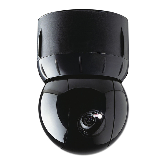
Figure 1. SpeedD om e U ltra Cam era Dome
Cam era Dome P ro d u ct Codes
P rod u ct
D e scrip tio n
ADSDU822N
22X, N, VERSION 1.00, BLACK
ADSDU822P
22X, P, VERSION 1.00, BLACK
ADSDU822WN
22X, N, VERSION 1.00, WHITE
ADSDU822WP
22X, P, VERSION 1.00, WHITE
ADSDU835N
35X, N, DAY/NIGHT, VERSION 1.00, BLACK
ADSDU835P
35X, P, DAY/NIGHT, VERSION 1.00, BLACK
ADSDU835WN
35X, N, DAY/NIGHT, VERSION 1.00, WHITE
ADSDU835WP
35X, P, DAY/NIGHT, VERSION 1.00, WHITE
© 2009 Sensormatic Electronics Corp.
SPEEDDOME ULTRA 8 CAMERA DOME
INSTALLATION AND SERVICE GUIDE
Contents
About this G uide...................................................... 1
About the Camera Dome........................................ 2
Cable Requirements................................................7
Power-Up Routine....................................................8
Synchronizing Domes............................................. 8
Diagnostic LE D s...................................................... 8
Warnings and Cautions.......................................... 9
Indoor Installation...................................................10
Using the Install/Removal T o ol............................ 14
Troubleshooting Indoor D om es........................... 16
Parts List for Authorized Users............................ 25
Specifications-Indoor Dome..................................27
Declarations........................................................... 29
Appendix A: Vicon Wiring Configurations............30
About this Guide
This guide explains how to connect the camera
dome to a mounting base and how to service it.
It does not explain how to:
•
Determine a mounting location for the camera
dome. The mounting location is determined by
customer requirements; therefore, this
information is provided separately.
• Attach the mounting base. See information
shipped with the base.
• Assemble housings and structures used with
this camera dome. See information shipped with
the housing and structure.
•
Program the camera dome. See operator's
guide shipped with the dome.
1 OF 30
8200-0600-03, REV. F1
Advertisement
Table of Contents

Related Manuals for American Dynamics SpeedDome Ultra 8


Summary of Contents for American Dynamics SpeedDome Ultra 8
-
Page 1: Table Of Contents
See information shipped with the housing and structure. • Program the camera dome. See operator's guide shipped with the dome. © 2009 Sensormatic Electronics Corp. SPEEDDOME ULTRA 8 CAMERA DOME 8200-0600-03, REV. F1 1 OF 30 INSTALLATION AND SERVICE GUIDE... -
Page 2: About The Camera Dome
Figure 2. M o u n tin g base and h o u sin g and About the Camera Dome eyeball asse m b ly The SpeedDome Ultra 8 camera dome (Figure 1): • Mounts indoors, or outdoors (with accessory outdoor enclosure) •... - Page 3 * Option in white, but can be painted to match decor. f Top hat housing/dome assembly also mounts to structure. SPEEDDOME ULTRA 8 CAMERA DOME 8200-0600-03, REV. F1 3 OF 30 INSTALLATION AND SERVICE GUIDE...
- Page 4 A D S D U P IV R S V a n d a l-R e s is ta n t B ubble RHIUCM RHIUPNDT RHIU3X3 RHIU4X4 SPEEDDOME ULTRA 8 CAMERA DOME 8200-0600-03, REV. F1 4 OF 30 INSTALLATION AND SERVICE GUIDE...
- Page 5 N o te : indoor use) in place of the environmental board. Figure 5. AD o u td o o r h o u sin g (o p tion al) SPEEDDOME ULTRA 8 CAMERA DOME 8200-0600-03, REV. F1 5 OF 30...
- Page 6 RHOWPA pole mount comes with the ROENDC end cap RHOSW/RHOLW wall mount comes with the ROENDC end cap RHOPN pendant mount RHOSW RHOWCA corner bracket only (shown with RHOLW mount) SPEEDDOME ULTRA 8 CAMERA DOME 8200-0600-03, REV. F1 6 OF 30 INSTALLATION AND SERVICE GUIDE...
-
Page 7: Cable Requirements
(such as a J-box) and the worst-case low line voltage. These lengths are for Sensormatic composite cables, which use 0.823mm2 (18AWG) ac power wires. SPEEDDOME ULTRA 8 CAMERA DOME 8200-0600-03, REV. F1 7 OF 30 INSTALLATION AND SERVICE GUIDE... -
Page 8: Install/Removal Tool For Base With I/O Board
If an RS-422 network is used, other LEDs on the board indicate that wiring is correct, reversed, open, or grounded. SPEEDDOME ULTRA 8 CAMERA DOME 8200-0600-03, REV. F1 8 OF 30 INSTALLATION AND SERVICE GUIDE... -
Page 9: Warnings And Cautions
2.5 of IEC 60950-1, and a Once disassembled, parts of housing and eyeball maximum of 250VA available. assembly are fragile and may break. Use extreme care! SPEEDDOME ULTRA 8 CAMERA DOME 8200-0600-03, REV. F1 9 OF 30 INSTALLATION AND SERVICE GUIDE... -
Page 10: Indoor Installation
• Coax: Connect to the I/O board BNC video cable extension and leave video config. • SpeedDome Ultra 8 housing and eyeball jumpers E4 and E5 across pins 1 and 2 assembly, 0101-0150-xx. (default position). These pins are closest to the video extension cable. - Page 11 "Data In +/ -" wires shorted Output 2 (40mA sync. max.) — Both LEDs o ff or open. Output 3 (40mA sync. max.) — Ground — SPEEDDOME ULTRA 8 CAMERA DOME 8200-0600-03, REV. F1 11 OF 30 INSTALLATION AND SERVICE GUIDE...
- Page 12 RS-422, Range: 601-699 PELCO "P," 9600 baud RS-422, Range: 701-799 PANASONIC UTC Tyco UTC PELCO UTC (Origins, Standard, & Extended) Manufacturing Use, Range: 901 -999 SPEEDDOME ULTRA 8 CAMERA DOME 8200-0600-03, REV. F1 12 OF 30 INSTALLATION AND SERVICE GUIDE...
- Page 13 SPEEDDOME ULTRA 8 CAMERA DOME 8200-0600-03, REV. F1...
-
Page 14: Using The Install/Removal Tool
The T-lanyard will prevent the skirt or bubble from falling. SPEEDDOME ULTRA 8 CAMERA DOME 8200-0600-03, REV. F1 14 OF 30... - Page 15 Figure 13. H ow to use the in sta ll/re m o v a l to o l Skirt or Bubble Attachment/Detachment SPEEDDOME ULTRA 8 CAMERA DOME 8200-0600-03, REV. F1 15 OF 30 INSTALLATION AND SERVICE GUIDE...
-
Page 16: Troubleshooting Indoor Domes
0.326mm2 (20-22 AWG) wire strippers • Install/Removal tool to connect/disconnect dome to indoor bases with I/O boards, and to attach/detach skirts and bubbles—without a ladder. SPEEDDOME ULTRA 8 CAMERA DOME 8200-0600-03, REV. F1 16 OF 30 INSTALLATION AND SERVICE GUIDE... - Page 17 P1 c o n n e c to r (S ensorN et 485 data) sales representative for repair instructions. Color Designation Not used. — Orange SensorNet 485 Yellow SensorNet 485 SPEEDDOME ULTRA 8 CAMERA DOME 8200-0600-03, REV. F1 17 OF 30 INSTALLATION AND SERVICE GUIDE...
- Page 18 (0.1 in) slotted screwdriver. Wider blade widths can damage connectors. • The dome contains electrostatic-sensitive PC boards. Use a ground strap when handling these boards. SPEEDDOME ULTRA 8 CAMERA DOME 8200-0600-03, REV. F1 18 OF 30 INSTALLATION AND SERVICE GUIDE...
- Page 19 On the bottom of the power supply board, check that the optical sensor is functioning and plugged into connector P3 on the power supply board. SPEEDDOME ULTRA 8 CAMERA DOME 8200-0600-03, REV. F1 19 OF 30 INSTALLATION AND SERVICE GUIDE...
- Page 20 Figure 16. R em oving the CPU board 6. Reverse the steps to reassemble. Figure 17. R em oving th e P/S board (underside of PC board) SPEEDDOME ULTRA 8 CAMERA DOME 8200-0600-03, REV. F1 20 OF 30 INSTALLATION AND SERVICE GUIDE...
- Page 21 Failure to do so can destroy both motor and pan gear. Verify pan gear turns freely! Figure 18. R em oving the pan m o to r SPEEDDOME ULTRA 8 CAMERA DOME 8200-0600-03, REV. F1 21 OF 30 INSTALLATION AND SERVICE GUIDE...
- Page 22 4. Detach slip ring connector (Figure 23). Figure 23. D etaching th e eyeball 4. Reverse the steps to reassemble. Ensure ribbon cable pins are inserted "face down". SPEEDDOME ULTRA 8 CAMERA DOME 8200-0600-03, REV. F1 22 OF 30 INSTALLATION AND SERVICE GUIDE...
- Page 23 5. Gently pry off the yoke bracket covering the camera/lens board to access the bearing assembly (Figure 25). Figure 25. R em oving the yoke brackets SPEEDDOME ULTRA 8 CAMERA DOME 8200-0600-03, REV. F1 23 OF 30 INSTALLATION AND SERVICE GUIDE...
- Page 24 Verify the tilt gear turns freely. (Figure 28). Figure 28. R em oving the yoke brackets SPEEDDOME ULTRA 8 CAMERA DOME 8200-0600-03, REV. F1 24 OF 30 INSTALLATION AND SERVICE GUIDE...
-
Page 25: Parts List For Authorized Users
Screw, M3x6, PHP 5801-1041-120 Optical Sensor 6003-0228-01 Slip Ring Assy. 2100-0005-02 Standoff, M3x16 LG SS (Qty. 5899-0055-03 Housing 0500-7255-02/03 Bearing Assy., Pan Gear 2510-0040-01 Trim Ring 0505-1281-01/02 SPEEDDOME ULTRA 8 CAMERA DOME 8200-0600-03, REV. F1 25 OF 30 INSTALLATION AND SERVICE GUIDE... - Page 26 PAL camera (WHT) -31 Color 35X NTSC camera (BLK) -32 Color 35X PAL camera (BLK) -35 Color 35X NTSC camera (WHT) -36 Color 35X PAL camera (WHT) SPEEDDOME ULTRA 8 CAMERA DOME 8200-0600-03, REV. F1 26 OF 30 INSTALLATION AND SERVICE GUIDE...
-
Page 27: Specifications-Indoor Dome
Current..........0.77A @ 16Vac Power on in-rush current........1.5A Lens and Bubble Densities Allowable drop out..........100ms Eyeball Lens..............f0 Bubbles: ADSDUCLR (Clear)..........f0 ADSDUSMK (Smoke)........... f0.5 SPEEDDOME ULTRA 8 CAMERA DOME 8200-0600-03, REV. F1 27 OF 30 INSTALLATION AND SERVICE GUIDE... - Page 28 Zoom stop....71X, 94X, 117X, 140X (default) 198X, 220X, 242X 163X, 186X, 209X, 232X, 255X, 278X, 301X, 324X, 347X, 370X, Zoom/Focus accuracy......... ±0.5% 393X, 420X Zoom/Focus accuracy.......... ±0.5% SPEEDDOME ULTRA 8 CAMERA DOME 8200-0600-03, REV. F1 28 OF 30 INSTALLATION AND SERVICE GUIDE...
-
Page 29: Declarations
Field-of-View Formulas: Other Declarations 3.2mm* x distance from camera (m) Thank you for using American Dynamics products. We = Horizontal view (m) support our products through an extensive and worldwide Focal length (mm) x Digital Zoom network of dealers. The dealer, through whom you originally 2.4mm** x distance from camera (m) -
Page 30: Appendix A: Vicon Wiring Configurations
Appendix A: Vicon Wiring Configurations In Vicon systems where domes support loop through, daisy chain the SpeedDome Ultra 8 domes off the last Vicon dome in the communications chain. Figure 31. S peedD om e U ltra 8 dom e lo o p -th ro u g h w irin g fro m V icon dom e...