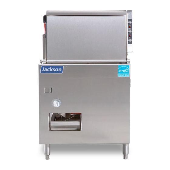
Jackson Delta 5-E Installation, Operation And Service Manual
Chemical sanitizing glasswasher dishmachine
Hide thumbs
Also See for Delta 5-E:
- Manual (2 pages) ,
- Installation, operation and service manual (48 pages)
Table of Contents
Advertisement
Quick Links
Advertisement
Table of Contents

Related Manuals for Jackson Delta 5-E


Summary of Contents for Jackson Delta 5-E
- Page 1 CHEMICAL SANITIZING GLASSWASHER DISHMACHINE INSTALLATION, OPERATION, AND SERVICE MANUAL FOR JACKSON MODEL: ® Delta Jackson WWS, Inc. 6209 N US HWY 25E Gray, KY 40734 Phone: (606) 523-9795 May 9, 2016 Fax: (606) 523-9196 07610-003-37-08-J www.jacksonwws.com...
- Page 2 NO EVENT TO EXCEED (18) EIGHTEEN MONTHS FROM DATE OF SHIPMENT FROM THE FACTORY. Jackson WWS agrees under this warranty to repair or replace, at its discretion, any original part which fails under normal use due to faulty material or workmanship during the warranty period, providing the equipment has been unaltered and has been properly installed, maintained, and operated in accordance with the applicable factory instruction manual and failure is reported to an authorized service agency within the warranty period.
- Page 3 REVISION/ REVISION MADE APPLICABLE DETAILS PAGE DATE 05-25-2007 Release to production. 10-04-2007 7934 Changed cover on power junction box. 05-20-2009 QOF 339 Updated programming page diagram. 04-26-2012 QOF 386 Updated location of door switch on schematic. 04-27-2012 QOF 386 Added EnergyStar logo. 03-08-13 QOF NDB-219 Updated company logo Added wiring change schematics.
- Page 4 Jackson WWS, Inc. provides technical support for all of the dishmachines detailed in this manual. Serial No.: Jackson strongly recommends that users refer to this manual before calling technical support staff. Installation Date: Users should have this manual on hand when calling technical support.
-
Page 5: Table Of Contents
Frame Assembly Hood Assembly Switch Panel Assembly Tub Assembly Frame & Motor Assembly Pump and Motor Assembly Booster Tank Assembly Incoming Plumbing Assembly Door Assembly Front Panel Assembly ELECTRICAL SCHEMATICS Delta 5-E 115V, 50/60 HZ, Single-Phase Delta 5-E Harness Connections... -
Page 6: Specification Information
SECTION 1: SPECIFICATION INFORMATION... -
Page 7: Specifications
NOTE: Always refer to the machine data plate for specific MINIMUM CHLORINE REQUIRED (PPM): electrical and water requirements. The material provided on this page is for reference only and may be subject to change without notice. Delta 5-E Installation, Operation, and Service Manual 07610-003-37-08-J Issued: 05-25-2007 Revised: 05-09-16... -
Page 8: Dimensions
21 1/4 (540 mm) 12 1/4 7 3/4 (311 mm) (197 mm) 3 (76 mm) (432 mm) 6 (152 mm) 6 3/4 (171 mm) 21 1/4 (540 mm) Delta 5-E Installation, Operation, and Service Manual 07610-003-37-08-J Issued: 05-25-2007 Revised: 05-09-16... -
Page 9: Installation/Operation Instructions
SECTION 2: INSTALLATION & OPERATION INSTRUCTIONS... -
Page 10: Installation Instructions
PLUMBING CHECK: Slowly turn on the water supply to the machine after connecting the incoming fill line and drain line. Check for leaks and repair as required. Leaks must be repaired prior to operating the machine. Delta 5-E Installation, Operation, and Service Manual 07610-003-37-08-J Issued: 05-25-2007 Revised: 05-09-16... -
Page 11: Electrical Installation Instructions
SECTION 2: INSTALLATION & OPERATION INSTRUCTIONS ELECTRICAL INSTALLATION INSTRUCTIONS ELECTRICAL POWER CONNECTION: DISCONNECT ELECTRICAL POWER SUPPLIES & TAG OUT IN ACCORDANCE WITH APPROPRIATE PROCEDURES & CODES AT THE DISCONNECT SWITCH TO INDICATE THE CIRCUIT IS BEING SERVICED. Electrical and grounding conductors must comply with the applicable portions of the National Electric Code ANSI/NFPA 70 (latest edition) and/or other electrical codes. -
Page 12: Operation Instructions
After the initial fill, the rinse water for the current cycle will become the wash water for the next cycle. The dishmachine is now ready to proceed with dishwashing. Delta 5-E Installation, Operation, and Service Manual 07610-003-37-08-J Issued: 05-25-2007 Revised: 05-09-16... - Page 13 2. Open doors and manually remove drain stopper to drain the unit. 3. Remove and clean upper and lower wash arms. 4. Remove and clean the sump strainer. Delta 5-E Installation, Operation, and Service Manual 07610-003-37-08-J Issued: 05-25-2007 Revised: 05-09-16...
-
Page 14: Chemical Dispensing Equipment
TO PREPARE CHEMICAL FEEDER PUMPS FOR OPERATION: The Delta 5-E dismachine is supplied with detergent, rinse additive, and sanitizer dispensing chemical feeder pumps. Locate the open ends of the chemical tubes with the tube stiffen- ers and place each one in the appropriate container. -
Page 15: Detergent Control
A loss of temperature can indicate a larger problem—such as a failed heater—or could indicate that the hot water heater for the operation is not up to capacity and a larger one may need to be installed. Delta 5-E Installation, Operation, and Service Manual 07610-003-37-08-J Issued: 05-25-2007 Revised: 05-09-16... - Page 16 SECTION 3: PREVENTATIVE MAINTENANCE...
-
Page 17: Preventative Maintenance
11. Always contact a qualified service agency whenever a serious problem arises. 12. Follow all safety procedures, whether listed in this manual or put forth by local, state or national codes/regulations. Delta 5-E Installation, Operation, and Service Manual 07610-003-37-08-J Issued: 05-25-2007 Revised: 05-09-16... - Page 18 SECTION 4: TROUBLESHOOTING...
-
Page 19: Troubleshooting Section
Problem: Little or no water coming through the rinse assemblies. CAUSE SOLUTION Limed up rinse heads or piping Delime rinse heads. Low water pressure Increase pipe size to machine. Adjust pressure regulator. Continued on next page. Delta 5-E Installation, Operation, and Service Manual 07610-003-37-08-J Issued: 05-25-2007 Revised: 05-09-16... - Page 20 Adjust as required. minimum criteria indicated on machine data plate Problem: No indication of pressure. CAUSE SOLUTION Water turned off Turn water on. Pressure gauge defective Replace pressure gauge. Delta 5-E Installation, Operation, and Service Manual 07610-003-37-08-J Issued: 05-25-2007 Revised: 05-09-16...
-
Page 21: Parts Section
SECTION 5: PARTS SECTION... -
Page 22: Chemical Feeder Pump Assembly
Mfg. No.: 04320-011-63-33 Mfg. No.: 04320-111-65-27 Tube, Small 7/32” (Use with the black roller.) Mfg. No.: 05700-011-65-21 1/4” Sight Tube Mfg. No.: N/A 3/8” Sight Tube Mfg. No.: 05700-111-35-33 Delta 5-E Installation, Operation, and Service Manual 07610-003-37-08-J Issued: 05-25-2007 Revised: 05-09-16... -
Page 23: Solenoid Valve Repair Parts
Arrestor, 1/2" NPT 06401-003-07-43 06685-100-05-00 Complete 220 Volt Solenoid Valve Assembly, 1/2” 04810-100-09-18 Coil & Housing only, 1/2” 06401-003-07-44 Close Nipple, 1/2” Tee, 1/2” x 1/2” x 1/2” 04730-207-15-00 04730-211-27-00 Delta 5-E Installation, Operation, and Service Manual 07610-003-37-08-J Issued: 05-25-2007 Revised: 05-09-16... -
Page 24: Control Box Assembly
SECTION 5: PARTS SECTION CONTROL BOX ASSEMBLY 9, 10 Normal/Delime Rinse Aid/Detergent Sanitizer 11, 27 11, 27 12, 13, 28 Delta 5-E Installation, Operation, and Service Manual 07610-003-37-08-J Issued: 05-25-2007 Revised: 05-09-16... - Page 25 SECTION 5: PARTS SECTION CONTROL BOX ASSEMBLY 16, 27 17, 28 18, 27 17, 28 24, 27 25, 26, 27 22, 23 Delta 5-E Installation, Operation, and Service Manual 07610-003-37-08-J Issued: 05-25-2007 Revised: 05-09-16...
- Page 26 Locknut, 10-24 S/S Hex with Nylon Insert 05310-373-01-00 Locknut, 6-32 S/S Hex with Nylon Insert 05310-373-03-00 Harness, Wash Pump 05700-003-35-34 Harness, Drain Solenoid 05700-003-35-36 Harness, Peri-pump 05700-003-35-35 Conduit, 1/2” x 17” 05700-003-35-49 Delta 5-E Installation, Operation, and Service Manual 07610-003-37-08-J Issued: 05-25-2007 Revised: 05-09-16...
-
Page 27: Peri-Pump Box Assembly
Tubing, 1/4’’ OD x 60” Long, Red 05700-011-63-18 Terminal Board (Not Shown) 05940-001-97-91 Tubing,1/4 OD x 120 Long Blue 05700-011-37-17 Tubing,1/4 OD x 120 Long Write 05700-011-37-13 Tubing,1/4 OD x 120 Long Red 05700-011-37-15 Delta 5-E Installation, Operation, and Service Manual 07610-003-37-08-J Issued: 05-25-2007 Revised: 05-09-16... -
Page 28: Electrical Connection Box Assembly
05940-200-76-00 Decal, Power Connection 09905-011-47-64 Decal, Warning to Disconnect Power 09905-100-75-93 Screw, 10-32 x 1/2’’ Long, Phillips Trusshead 05305-011-39-36 Decal, Copper Conductors Only 09905-011-47-35 Cover, Solenoid Box 05700-003-46-72 Delta 5-E Installation, Operation, and Service Manual 07610-003-37-08-J Issued: 05-25-2007 Revised: 05-09-16... -
Page 29: Frame Assembly
05700-003-09-31 Locknut, 1/4”-20 S/S Hex with Nylon Insert 05310-374-01-00 Nut, Hex 1/4”-20 05310-274-01-00 Booster Mounting Plate Weldment 05700-002-51-93 Bracket, Temperature Gauge 05700-003-14-53 Bolt, 1/4”-20 x 1/2” Long 05305-274-02-00 Delta 5-E Installation, Operation, and Service Manual 07610-003-37-08-J Issued: 05-25-2007 Revised: 05-09-16... -
Page 30: Hood Assembly
Bracket, Limit Switch 05700-021-71-18 Locknut, 10-24 with Nylon Insert 05310-373-01-00 Clamp, Pipe 5/8” 05700-000-35-06 Rack Rail Weldment 05700-002-45-67 Washer, 1/4”-20 I.D. 05311-174-01-00 Gasket, Side Panel (5.3 Feet) 05700-003-35-51 Delta 5-E Installation, Operation, and Service Manual 07610-003-37-08-J Issued: 05-25-2007 Revised: 05-09-16... -
Page 31: Switch Panel Assembly
Light, Amber 05945-504-06-18 Light, Red 05945-504-07-18 Decal, Switch Panel 09905-003-08-63 Fitting, .25-.546 05975-011-65-51 Plug, 3/4” hole 04730-011-60-21 Locknut, 10-24 with Nylon Insert 05310-373-01-00 Washer, #10 05311-173-02-00 Terminal Board 05940-001-97-91 Delta 5-E Installation, Operation, and Service Manual 07610-003-37-08-J Issued: 05-25-2007 Revised: 05-09-16... -
Page 32: Tub Assembly
SECTION 5: PARTS SECTION TUB ASSEMBLY Delta 5-E Installation, Operation, and Service Manual 07610-003-37-08-J Issued: 05-25-2007 Revised: 05-09-16... - Page 33 Clamp, 1” Nylon (Not Shown, located on bottom of tub.) 04730-002-41-88 Drain Solenoid Box Assembly 05700-003-09-61 Solenoid Box Weldment 05700-003-35-88 Drain Solenoid, 115V 04810-200-11-00 Locknut, 10-24 with Nylon Insert 05310-373-01-00 Decal, Warning 09905-100-75-93 Solenoid Box Cover 05700-003-30-25 Delta 5-E Installation, Operation, and Service Manual 07610-003-37-08-J Issued: 05-25-2007 Revised: 05-09-16...
-
Page 34: Frame & Motor Assembly
SECTION 5: PARTS SECTION FRAME AND MOTOR ASSEMBLY See Motor Assembly Page See Plumbing Assembly Page See Booster Assembly Page See Frame Assembly Page Delta 5-E Installation, Operation, and Service Manual 07610-003-37-08-J Issued: 05-25-2007 Revised: 05-09-16... - Page 35 05310-374-01-00 Washer, 1/4”-20 S/S 05311-174-01-00 Hose Clamp, 13/16 TO 1 1/2” 04730-719-06-09 Hose Clamp, 1 1/16” to 2 1/4” 04730-719-18-00 Close Nipple, 1/2” Brass 04730-207-15-00 Gauge, Thermometer 06685-111-68-48 Delta 5-E Installation, Operation, and Service Manual 07610-003-37-08-J Issued: 05-25-2007 Revised: 05-09-16...
-
Page 36: Pump And Motor Assembly
Lockwasher, 3/8” Mfg. No.: 05311-276-01-00 Motor Mounting Bracket Mfg. No.: 05700-002-55-52 Nut, Hex 3/8”-16 S/S Mfg. No.: 05310-276-01-00 Bolt, 3/8” x 3/4” Long Hex Head Mfg. No.: 05306-011-71-60 Delta 5-E Installation, Operation, and Service Manual 07610-003-37-08-J Issued: 05-25-2007 Revised: 05-09-16... -
Page 37: Booster Tank Assembly
Decal, Warning-Disconnect Power 09905-100-75-93 Probe, Thermistor 06685-004-17-26 Cover, Heater Box 05700-004-34-90 Thermostat, Elan Electric (Dual) 06685-004-17-27 Spacer, 1/4 OD x 9/32 09330-004-34-91 Nut, Lock 6-32 Hex w/Nylon Insert 05310-373-03-00 Delta 5-E Installation, Operation, and Service Manual 07610-003-37-08-J Issued: 05-25-2007 Revised: 05-09-16... -
Page 38: Incoming Plumbing Assembly
05700-001-08-28 Union, 1/2’’, Copper to Copper 04730-412-05-01 Elbow, 607, 1/2’’ Copper to Copper 04730-406-01-01 Tube, Copper, 1/2’’ x 4 1/4’’ Long 05700-001-01-60 Elbow, 90° (CU to MSPS) 04730-406-32-01 Delta 5-E Installation, Operation, and Service Manual 07610-003-37-08-J Issued: 05-25-2007 Revised: 05-09-16... -
Page 39: Door Assembly
Locknut, 6-32 S/S Hex with Nylon Insert 05310-373-03-00 Locknut, 1/4”-20 S/S Hex with Nylon Insert 05310-374-01-00 Nut, Hex 1/4”-20 S/S 05310-274-01-00 Bolt, 1/4”-20 Eye, S/S 05306-002-55-59 Spring, Door 05340-011-44-58 Delta 5-E Installation, Operation, and Service Manual 07610-003-37-08-J Issued: 05-25-2007 Revised: 05-09-16... -
Page 40: Front Panel Assembly
SECTION 5: PARTS SECTION FRONT PANEL ASSEMBLY ITEM DESCRIPTION Mfg. No. Complete Panel Assembly 05700-003-09-53 Panel Weldment 05700-003-09-54 Handle 05340-001-96-30 Delta 5-E Installation, Operation, and Service Manual 07610-003-37-08-J Issued: 05-25-2007 Revised: 05-09-16... -
Page 41: Electrical Schematics
SECTION 6: ELECTRICAL SCHEMATICS... -
Page 42: Delta 5-E 115V, 50/60 Hz, Single-Phase
SECTION 7: ELECTRICAL SCHEMATICS DELTA 5-E 115V, 50/60 HERTZ, SINGLE PHASE Delta 5-E Installation, Operation, and Service Manual 07610-003-37-08-J Issued: 05-25-2007 Revised: 05-09-16... -
Page 43: Delta 5-E Harness Connections
SECTION 6: ELECTRICAL SCHEMATICS DELTA 5-E HARNESS CONNECTIONS DELTA 5-E Probe Delta 5-E Installation, Operation, and Service Manual 07610-003-37-08-J Issued: 05-25-2007 Revised: 05-09-16... - Page 44 TECHNICAL MANUAL FOR JACKSON MODEL: Delta ® 5-E Jackson WWS, Inc. 6209 N US HWY 25E Gray, KY 40734 May 9, 2016 Phone: (606) 523-9795 Fax: (606) 523-9196 07610-003-37-08-J www.jacksonwws.com...