
Related Manuals for Jackson DELTA 115


Summary of Contents for Jackson DELTA 115
- Page 1 INSTALLATION, OPERATION, AND SERVICE MANUAL ® DELTA SERIES GLASSWASHER DISHMACHINES Delta 1200/115 Manual • Rev Q • 07610-003-62-15 • Issued: 10-27-08 • Revised: 9-19-16 ®...
- Page 3 The labor to repair or replace such failed part will be paid by Jackson WWS, within the continental United States, Hawaii, and Canada, during the warranty period provided a Jackson WWS authorized service agency, or those having prior authorization from the factory, performs the service.
- Page 4 Updated detergent squeeze tube P/N. Updated and labeled rinse-aid and sanitizer squeeze tubes, pgs. 33-34. 10-08-15 Updated item #9 P/N to 05700-003-60-38 on pg. 32. 11-19-15 ECN-8336 Added Delta 115 and associated schematics, etc. 01-19-16 QOF-386 Updated schematic on pg. 47. 04-26-16 ECN-8379 Updated schematic on pg.
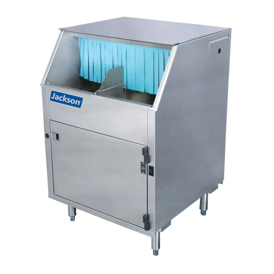
- Page 5 ® 115 V glasswasher dishmacine; chemical-sanitizing, carousel-type, electric tank heat, with detergent, rinse-aid, and sanitizer chemical feeder pumps. Jackson WWS, Inc. provides technical support for all of the dishmachines detailed in this manual. We strongly recommend that you refer to this manual before making a call to our technical support staff.
-
Page 7: Table Of Contents
Wash Tank Heater Replacement ....................24 Thermostat Replacement ....................... 29 Wash Motor Replacement ......................32 PARTS Control Box Assembly - Delta 115 ....................35 Control Box Assembly - Delta 1200 ....................36 Outer Shell Assembly ........................37 Chemical Feeder Pump Assembly ....................38 Rinse Assembly .......................... -
Page 8: Guide To Symbols
GUIDES GUIDES SYMBOLS - risk of injury to personnel. WARNING - risk of damage to equipment. CAUTION - risk of electrical shock. - reference data plate. - caustic chemicals. - ground wire. - lockout electrical power. - important note. NOTICE ABBREVIATIONS &... -
Page 9: Specifications
MACHINE DIMENSIONS SPECIFICATIONS LEGEND A - Designates the machine's rightmost side from the front. B- Designates the machine's base. 25.25" LEGEND Scale = 0.09:1 All dimensions from the floor can be increased 1 1/4" with 9.50" the machine's adjustable feet. A = Designates the machine’s rightmost side from the front 5.00"... -
Page 10: Operating Parameters
OPERATING PARAMETERS SPECIFICATIONS Operating Capacity: Delta 1200 Delta ® ® Glasses per Hour 1200 1200 Operating Cycle: Total Cycle Time 1200 1200 Tank Capacity (Gallons): Wash Pump Capacity (GPM): Water Temperatures (°F): Minimum Wash Temperature Minimum Rinse Temperature Other Water Requirements: Cold Water Flow Pressure (PSI) 8-12 8-12... -
Page 11: Electrical Requirements
ELECTRICAL REQUIREMENTS SPECIFICATIONS NOTICE Delta 1200 ® Electrical Characteristics All electrical ratings provided in this manual are for reference only. Always refer to the machine data plate to get exact electrical VOLTS information for this machine. All electrical work performed on machines should be done in accordance with applicable local, state, territorial, and national codes. -
Page 12: Instructions
INSTRUCTIONS INSTALLATION VISUAL INSPECTION Before installing the unit, check packaging and machine for damage. Damaged packaging might be an indication of damage to the machine. If there is any type of damage to both packaging and unit, do not throw away the packaging. The Do not throw away dishmachine has been inspected at the factory before shipping and is expected to container if damage is... - Page 13 INSTRUCTIONS INSTALLATION PRESSURE The manufacturer has an optional water pressure regulator to accommodate areas where water pressure fluctuates or is higher than the recommended pressure. Take REGULATOR care not to confuse static pressure with flow pressure: static pressure is line pressure in a “no flow”...
- Page 14 INSTRUCTIONS INSTALLATION ELECTRICAL POWER Electrical and grounding conductors must comply with the applicable portions of the National Electric Code ANSI/NFPA 70 (latest edition) and/or other electrical codes. CONNECTIONS The data plate is on the ride side of the door. Refer to the data plate for machine operating requirements, machine voltage, total amperage, and serial number.
- Page 15 INSTRUCTIONS INSTALLATION THERMOSTATS The thermostats on this dishmachine have been set at the factory. They should only be adjusted by an authorized service agent. CHEMICAL FEEDER CAUTION! Chlorine-based sanitizers can be detrimental to this machine if the chemical solution is too strong. See a chemical EQUIPMENT professional to ensure the dispenser is set-up correctly.
-
Page 16: Operating Instructions
OPERATING INSTRUCTIONS OPERATION PREPARATION Before operating the unit, verify the following: 1. Wash strainer is clean and in place. 2. Rinse strainer is clean and in place. 3. The drain stopper is installed. 4. Chemical levels in chemical containers are correct. FILLING THE 1. - Page 17 OPERATING INSTRUCTIONS OPERATION WARE Proper preparation of ware will help ensure good results and fewer re-washes. If not done properly, ware might not come out clean and the efficiency of the dishmachine PREPARATION will be reduced. Scraps should always be removed from ware before being loaded onto the carousel.
- Page 18 OPERATING INSTRUCTIONS OPERATION SHUTDOWN AND 3. Remove and clean the wash strainer. CLEANING 4. Remove and clean the drain stopper. 5. Remove the curtain, clean with a mild soap, and rinse. 6. Remove and clean the drain boards. 7. Remove and clean the rack cylinder. 07610-003-62-15-Q...
- Page 19 OPERATING INSTRUCTIONS OPERATION SHUTDOWN AND 8. Hold paddle switch against wall of machine with one hand. CLEANING 9. Remove carousel with other hand and clean the carousel. 10. Push the wash and rinse arms away from their manifolds and remove. Remove end-caps, clean with a brush, and flush with fresh water.
- Page 20 OPERATING INSTRUCTIONS OPERATION AFTER 1. Spray or wipe out interior of machine. CLEANING 2. Replace the rinse strainer. 3. Replace the separator and upper rinse strainer. 4. Replace wash/rinse arms and verify end-caps have been tightened. 5. Replace the carousel. 07610-003-62-15-Q...
- Page 21 OPERATING INSTRUCTIONS OPERATION AFTER 6. Replace the rack cylinder. CLEANING 7. Replace the drain boards. 8. Replace the curtain. 9. Replace the drain stopper. 10. Replace the wash strainer. 11. Use stainless steel polish to clean and protect outside of dishmachine. 07610-003-62-15-Q...
- Page 22 OPERATING INSTRUCTIONS OPERATION DETERGENT Detergent usage and water hardness are two factors that contribute greatly to how efficiently this dishmachine will operate. Using detergent in the proper amount can CONTROL become a source of substantial savings. A qualified water treatment specialist can determine what is needed for maximum efficiency from the detergent.
-
Page 23: Maintenance
PREVENTATIVE MAINTENANCE MAINTENANCE PREVENTATIVE The manufacturer highly recommends that any maintenance and repairs not specifically discussed in this manual be performed only by QUALIFIED SERVICE PERSONNEL. MAINTENANCE Performing maintenance on your dishmachine may void your warranty, lead to larger problems, or even cause harm to the operator. By following the operating and cleaning instructions in this manual, you should get the most efficient results from your machine. -
Page 24: Troubleshooting
COMMON PROBLEMS TROUBLESHOOTING WARNING: Inspection, testing, and repair of electrical equipment should only be performed by qualified service personnel. Certain procedures in this section require electrical tests or measurements while power is applied to the machine. Exercise extreme caution at all times. If test points are not easily WARNING accessible, disconnect power, attach test equipment, and reapply power to test. - Page 25 COMMON PROBLEMS TROUBLESHOOTING PROBLEM POSSIBLE CAUSE REMEDY 1. Loose wire connection to limit switch 1. Tighten wires. or relay. 2. Replace pump motor. 2. Faulty pump motor. Wash motor 3. If motor has correct incoming voltage, and the overload does not run; 3.
- Page 26 COMMON PROBLEMS TROUBLESHOOTING PROBLEM POSSIBLE CAUSE REMEDY 1. Power supply shorted to ground. 1. Check for loose wires/burned connection. Replace or repair as required. Machine keeps 2. Pump impeller jammed. tripping service 2. Disassemble and remove obstruction. breaker. 3. Wash pump motor faulty. 3.
- Page 27 COMMON PROBLEMS TROUBLESHOOTING PROBLEM POSSIBLE CAUSE REMEDY Sanitizer pump 1. Faulty sanitizer pump motor. 1. If you read line voltage at the sanitizer motor terminals doesn't run during the sanitizer feed cycle, replace the motor. during cycle or 2. Faulty prime switch. through prime 2.
-
Page 28: Service Procedures
SERVICE PROCEDURES SERVICE CHEMICAL FEEDER CAUTION! Many of the instructions and steps within this document require the use of tools. Only authorized personnel should ever PUMP MOTOR perform any maintenance procedure on the dishmachine! CAUTION REPLACEMENT PREPARATION • Power must be secured to the unit at the service breaker. Tag or lock-out the service breaker to prevent accidental or unauthorized energizing of the These machines come machine. - Page 29 SERVICE PROCEDURES SERVICE CHEMICAL FEEDER 4. Determine which motor you wish to replace, or which one you wish to start with. Trace the wire leading from the motor to its corresponding prime switch. PUMP MOTOR Trace the other wire from the motor to determine where it is connected. REPLACEMENT 5.
- Page 30 SERVICE PROCEDURES SERVICE CHEMICAL FEEDER 10. Once the screws are removed, the motor should drop away. PUMP MOTOR REPLACEMENT 11. Cut away any tie-wraps that are holding the power wires and remove the motor. 12. Take your new motor and attach new terminals to the wires as required. 13.
-
Page 31: Wash Tank Heater Replacement
SERVICE PROCEDURES SERVICE WASH TANK HEATER CAUTION! Many of the instructions and steps within this document require the use of tools. Only authorized personnel should ever REPLACEMENT perform any maintenance procedure on the dishmachine! CAUTION PREPARATION • Power must be secured to the unit at the service breaker. Tag or lock-out the service breaker to prevent accidental or unauthorized energizing of the These machines come machine. - Page 32 SERVICE PROCEDURES SERVICE WASH TANK HEATER 3. Remove the lower strainer. REPLACEMENT 4. Remove the ELAN thermostat using a phillips screwdriver. Either unplug the wires or cut the wire-tie and let the thermostat hang down out of the way. 5. Remove the thermostat bracket with the 3/8” nutdriver. 6.
- Page 33 SERVICE PROCEDURES SERVICE WASH TANK HEATER 8. Using a 1/2” socket or wrench, remove the heater mounting nuts. REPLACEMENT 9. Removing the heater might require that you reach into the wash tank, grasp it, and give it a push out of the wash tank. 10.
- Page 34 SERVICE PROCEDURES SERVICE WASH TANK HEATER 15. Place the heater wires on the heater and tighten the nuts down using the 3/8” nutdriver (Step 7 in reverse). REPLACEMENT 16. Using the torque wrench or a torque nutdriver (if available) torque the nuts holding the wires, jumpers, and bus bars to 16 in-lbs.
- Page 35 SERVICE PROCEDURES SERVICE WASH TANK HEATER 24. Replace the heater cover (Step 2 in reverse). REPLACEMENT 25. Replace the front door. AFTER MAINTENANCE ACTIONS • Service personnel might want to drain the machine and allow it to cool down. Secure power to the unit at the service breaker and then verify the torque of all fasteners covered in this instruction.
-
Page 36: Thermostat Replacement
SERVICE PROCEDURES SERVICE THERMOSTAT CAUTION! Many of the instructions and steps within this document require the use of tools. Only authorized personnel should ever REPLACEMENT perform any maintenance procedure on the dishmachine! CAUTION PREPARATION • Power must be secured to the unit at the service breaker. Tag or lock-out the service breaker to prevent accidental or unauthorized energizing of the These machines machine. - Page 37 SERVICE PROCEDURES SERVICE THERMOSTAT 3. Using the pair of needle-nose pliers (if necessary), disconnect the terminals from the thermostat probe. Be careful not to damage the terminals or the REPLACEMENT wires or they will have to be replaced. 4. Unplug all of the terminals/wires connected to the ELAN thermostat. 5.
- Page 38 SERVICE PROCEDURES SERVICE THERMOSTAT 8. Pull the thermostat probe out of the wash tank. REPLACEMENT 9. Place the new thermostat probe in the new imperial brass fitting provided in your kit. Use the 7/16” wrench to tighten it down after getting the fitting hand- tight in the tank.
-
Page 39: Wash Motor Replacement
SERVICE PROCEDURES SERVICE WASH MOTOR CAUTION! Many of the instructions and steps within this document require the use of tools. Only authorized personnel should ever REPLACEMENT perform any maintenance procedure on the dishmachine! CAUTION PREPARATION • Power must be secured to the unit at the service breaker. Tag or lock-out the service breaker to prevent accidental or unauthorized energizing of the These machines come machine. - Page 40 SERVICE PROCEDURES SERVICE WASH MOTOR 2. Using the 5/16” nutdriver, loosen the clamps on the suction hose. REPLACEMENT 3. Using the same nutdriver, loosen the disharge hose where it connects to the tub weldement. 4. Pull the discharge hose out and away from the tub. 5.
- Page 41 SERVICE PROCEDURES SERVICE WASH MOTOR 7. Turn the motor so that you will have access to the wiring cover on the back. Be careful not to pull or yank too hard as the motor is still connected to the REPLACEMENT unit by way of the power lines.
-
Page 42: Parts
CONTROL BOX ASSEMBLY - DELTA 115 PARTS ITEM DESCRIPTION PART NUMBER Fitting 05975-011-49-03 Fitting 05975-011-65-51 Ground Lug 05940-200-76-00 Separator 05700-011-40-05 Transformer 05950-002-16-78 Relay 05945-111-35-19 Contactor 05945-109-05-69 Access Panel 05700-003-55-38 Decal, Warning, Disconnect Power 09905-004-08-16 Decal, Caution 09905-011-68-99 Terminal Board 05940-002-78-97... -
Page 43: Control Box Assembly - Delta 1200
CONTROL BOX ASSEMBLY - DELTA 1200 PARTS ITEM DESCRIPTION PART NUMBER Fitting 05975-011-49-03 Fitting 05975-011-65-51 Bracket 05700-003-56-00 Capacitor 05910-003-43-01 Ground Lug 05940-200-76-00 Separator 05700-011-40-05 Transformer 05950-011-61-67 Relay 05945-111-47-51 Contactor 05945-002-74-20 Access Panel 05700-003-55-38 Decal, Warning, Disconnect Power 09905-004-08-16 Decal, Caution 09905-011-68-99 Terminal Board 05940-002-78-97... -
Page 44: Outer Shell Assembly
OUTER SHELL ASSEMBLY PARTS ITEM DESCRIPTION PART NUMBER Outer Cover 05700-003-57-95 Bushing 05975-210-03-00 Access Cover 05700-003-58-73 Bullet Foot 05340-108-01-03 Switch Cover 05700-003-60-39 Power Switch 05930-011-61-69 Curtain 08415-003-60-35 Jackson Decal 09905-004-03-02 Curtain Rod 05700-003-60-38 07610-003-62-15-Q... -
Page 45: Chemical Feeder Pump Assembly
CHEMICAL FEEDER PUMP ASSEMBLY PARTS ITEM DESCRIPTION PART NUMBER 14 RPM Peri-Pump 05700-003-87-08 Cover and Peri-Pump Assembly 05700-003-55-29 Cover only 05700-003-55-34 Sanitizer Tube Replacement Kit 06401-003-61-21 Rinse Aid Tube Replacement Kit 06401-003-61-22 Detergent Tube Replacement Kit 06401-003-61-23 Rinse Aid & Sanitizer Squeeze Tubes 05700-011-65-21 Detergent Squeeze Tube 05700-003-22-89... -
Page 46: Rinse Assembly
RINSE ASSEMBLY PARTS Vacuum Breaker Assembly 05700-003-55-31 Rinse Tube 05700-003-49-32 Entire Plumbing Assembly 05700-003-58-77 *Delta 115 has a different part number. See parts list on the next page. 07610-003-62-15-Q... - Page 47 04730-111-48-87 Fitting, 3/8" NPT x 1/2" Barbed 04730-002-18-54 Cover, Solenoid Assembly 05975-111-62-70 Solenoid Valve Delta 1200 04730-011-61-54 Solenoid Valve Delta 115 04730-002-75-48 3/8" Close Nipple 04730-002-18-00 Union, 3/8" NPT Straight Brass 04730-003-60-57 Tee, 3/8" x 3/8" x 3/8" MNPT 04730-011-61-53...
-
Page 48: Wash System
WASH SYSTEM PARTS See previous page. Wash Tube 05700-003-49-32 *Delta 115 has a different part number. See parts list on the next page. 07610-003-62-15-Q... - Page 49 Hose, 3/4” OD 04720-003-57-29 Pump Suction Hose 05700-003-60-25 Pump Hose Connector 04730-003-40-64 Pump Discharge Hose 05700-003-59-96 Wash Pump (Delta 1200) 06105-003-44-22 Wash Pump (Delta 115) 05700-004-26-50 Bracket, Wash Pump 05700-003-56-41 Drain Weldment 05700-003-60-00 Hexnut, 1/2”-13 S/S 05310-011-72-58 Thermostat Probe 06685-004-17-26 Washer, 1/2”...
-
Page 50: Conveyor & Drive System
CONVEYOR & DRIVE SYSTEM PARTS *Delta 115 has a different part number. See parts list on the next page. 07610-003-62-15-Q... - Page 51 Drive Gear 09330-003-58-32 Washer 05330-003-41-75 Extension Spring 05340-003-41-83 Gear Motor Box 05700-003-48-87 Gear Motor (Delta 1200) 06105-003-44-23 Gear Motor (Delta 115) 06105-004-26-30 Gear Motor Box Cover 05700-003-48-57 Lock Nut, 6-32 05310-373-03-00 Switch Mounting Bracket 05700-003-60-13 Liquidtite Fitting 05975-011-49-03 Limit Switch...
-
Page 52: Door Assembly
DOOR ASSEMBLY PARTS ITEM DESCRIPTION PART NUMBER Door Weldment 05700-002-24-40 Handle, Door Glasswasher 05340-001-96-30 Decal - Off/Fill/On 09905-011-61-70 Hinge 05340-021-62-04 Starwasher, External Tooth 05311-273-02-00 Screw 10-24 X 3/8 05305-173-03-00 Decal, Operating Instructions 09905-021-64-88 07610-003-62-15-Q... -
Page 53: Schematics
DELTA 115 SCHEMATICS 07610-003-62-15-Q... -
Page 54: Delta 1200
DELTA 1200 SCHEMATICS 07610-003-62-15-Q... - Page 56 Jackson WWS, Inc. • 6209 N. US Hwy 25E • Gray, KY 40734 USA 1.888.800.5672 • www.jacksonwws.com Delta 1200/115 Manual • Rev Q • 07610-003-62-15 • Issued: 10-27-08 • Revised: 9-19-16 ®...