Advertisement
Quick Links
Important: Due to the added weight of the UltraVac, it is important to ensure the parking brake on your
mower is adjusted properly. Before installing the UltraVac, make sure to re-adjust the parking brake on
your mower as outlined in the "Adjusting the Parking Brake" procedure in the Maintenance section of
the mower Operator's manual.
Loose Parts
Use the chart below to verify that all parts have been shipped. Part numbers not shown are available on the dealer
extranet.
Dealer Pack
Part No.
—
Literature Pack
Manual-Operator's
© 2019—Exmark Mfg. Co., Inc.
2101 Ashland Ave
Beatrice, NE 68310
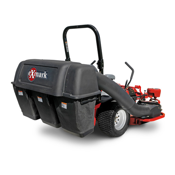
ULTRAVAC® COLLECTION SYSTEM
LZUV2B, LZUV3B, LZUVQD7, LZUVQD11
Description
Setup Instructions
For UltraVac Serial Nos. 406,294,345 & Higher
(To fit Lazer Z Units Serial Nos. 790,000 & Higher)
Qty.
Fill out the online warranty registration
form.
All Rights Reserved *4504-775* A
Part No. 4504-775 Rev. A
Printed in the USA.
Use
Advertisement

Related Manuals for Exmark ULTRAVAC LZUV2B


Summary of Contents for Exmark ULTRAVAC LZUV2B
- Page 1 Part No. Description Qty. Fill out the online warranty registration — form. Literature Pack Manual-Operator's © 2019—Exmark Mfg. Co., Inc. All Rights Reserved *4504-775* A Part No. 4504-775 Rev. A 2101 Ashland Ave Printed in the USA. Beatrice, NE 68310...
- Page 2 Models and Required Completing Kits Completing Kits Note: Use the following charts to verify the kits required for the unit you are installing the UltraVac on. Fits Lazer Z Serial Nos. 790,000–849,999: Lazer Z (LZZ) Deck Bag Style Quick Dump Completing Kit 2-Bagger 7-Bushel...
- Page 3 Fits Lazer Z Serial Nos. 920,000 and Higher: Lazer Z X-Series (LZX) Deck Bag Style Quick Dump Completing Kit 2-Bagger 7-Bushel 109-9623 2-Bagger 7-Bushel 109-9625 3-Bagger 11-Bushel 109-9627 3-Bagger 11-Bushel 109-9629 Lazer Z S-Series (LZS) Deck Bag Style Quick Dump Completing Kit 2-Bagger 7-Bushel...
- Page 4 Quick Dump Diagram Description Tube, Upper Description Asm, Reinforced Bumper LH W/Decal Asm, Hopper Cover, Belt Mount, Pivot Belt Asm, Dump Handle Sheave, Drive Asm, Handle Linkage Nut, #10 Nyloc Pin, Clevis Spring Screw, #10-24 CRPH Pin, Cotter Nut, Lock 1/2-13 Washer (11-Bushel) Asm, Bagger Mount Pin Washer (7-Bushel)
- Page 5 11-BUSHEL G031866 11-BUSHEL g031866 Figure 1...
- Page 6 Bagger Diagram Description Tube, Upper Description Nut, Lock 1/2-13 Asm, Hood Asm, Bagger Mount Pin Wld, Lower Mount Nut, Whizlock 3/8-16 (3-Bagger) Bolt, Carriage 3/8-16 x 1 1/4 Bolt, Square Hd 3/8-16 x 4 (3-Bagger) Nut, Nyloc 3/8-16 Flg Mount, Upper Bagger Bolt, Carriage 3/8-16 x 2 1/2 Asm, Bag &...
- Page 7 g031867 Figure 2...
- Page 8 Adjusting the Parking Brake Re-adjust the parking brake on your mower as outlined in the “Adjusting the Parking Brake” procedure in the Maintenance section of the mower Operator's manual. Adjusting the Muffler Guard The muffler guard needs to be repositioned to provided clearance when installing the UltraVac.
- Page 9 Installing the Upper and Lower Mount the upper bracket to the rear guard using two 1/2-13 x 2 1/2 inch carriage bolts and two 1/2-13 Bagger Mount Brackets–Propane inch nyloc nuts Units Install the lower mount bracket using four 3/8-16 Remove the hardware from the two outer square x 1 1/4 inch carriage bolts and four 3/8-16 inch holes in the rear guard panel shown in Figure 6.
- Page 10 Mount the 1/4 inch thick weight mounting plate to Weight Quantities the front panel of the toe board using four 3/8-16 x 1 1/4 inch hex head screws, four washers, four Deck 48 inch 52 inch 60 inch 72 inch Size 3/8-16 nyloc nuts.
- Page 11 Note: The portions of the UltraVac collection system that are not bolted to the mower are designed to be installed or removed in their entirety. Do Not operate the mower with only a portion of the UltraVac installed. Installing the Weight Assembly-Propane Units Note: The removable weights are heavy.
- Page 12 Insert the clevis pin through the bracket hole and fasten with a hairpin. Tighten knob on weight assembly until the weight is clamped securely to the caster arm. Note: The portions of the UltraVac collection system that are not bolted to the mower are designed to be installed or removed in their entirety.
- Page 13 towards nut (see Figure 16). Torque the sheave nut to 140-145 ft-lb (190–197 N-m). • For LZA/LZE Units: Install the double sheave onto the right spindle shaft and install the nut. Torque the sheave nut to 140-145 ft-lb (190–197 N-m). Block the blade rotation with a block of wood between the blade and baffles as indicated in the blade service section of the Lazer Z...
-
Page 14: Installing The Blower Assembly
g009348 Figure 18 g009340 Figure 19 1. 5/8-18 inch sheave nut-torque to 90-110 ft-lb (122-149 N-m) 2. UltraVac drive sheave 1. Nut 2. Belt guide 3. Special tool 109-2979 Mount the blower on the deck by inserting the Reinstall blade and torque blade bolt to: mounting pin into the tube welded to the rear corner of the deck (see Figure 20). - Page 15 g007017 Figure 21 Small Decks — View from Top of Blower 1. Spring loaded idler 4. Belt guide 2. Impeller sheave 5. Deck sheave g032161 3. Fixed idler Figure 23 1. Blower 3. Mower frame For Large Decks: 2. Belt cover Pull the spring loaded idler back and slip the belt over the top deck sheave.
- Page 16 g009314 Figure 27 7-Bushel Units Only 1. Knob 3. Carriage bolt 2. Dump handle 4. Rotate outward g008641 Figure 25 Lift the hopper assembly and pivot it upward towards 1. 3/8-16 x 1 1/4 inch carriage bolt the back of the unit (see Figure 28). 2.
- Page 17 Align the holes in the mount pin and frame mount barrel and insert the hairpin to lock the hopper assembly into place. Tighten the hardware on the exhaust diverter. For 2-Bagger & 3-Bagger Units: Raise the hood and install the bag assemblies by sliding the bag frame hooks onto the retaining g009351 Figure 30...
- Page 18 hex washer head screws, three #10 washers, and three #10-24 nyloc nuts. The screw head should be installed to the inside of the tube to provide minimum obstruction to flow. Make sure that the upper and the lower ends are oriented properly as the tubes are assembled.
- Page 19 Adjusting the Door Linkage Note: The Quick Dump units were adjusted at the factory to operate properly. However, adjustments can be made if your unit requires them: 7-Bushel Units: If the door does not close properly adjust the rods as shown in Figure 33. •...
- Page 20 11-Bushel Units: g009316 Figure 34 11-Bushel Units 1. Handle Link 3. Stop 5. Latches 4. Hinge Links 2. Stop Screws Door closing: The closing of the door is controlled by the two hinge links and the two stop screws (see Figure 34).