Exmark ULTRAVAC LZUVQD7 Operator's Manual
Collection system
Hide thumbs
Also See for ULTRAVAC LZUVQD7:
- Operator's manual (32 pages) ,
- Setup instructions (20 pages)
Table of Contents
Advertisement
Quick Links
Advertisement
Table of Contents

Related Manuals for Exmark ULTRAVAC LZUVQD7


Summary of Contents for Exmark ULTRAVAC LZUVQD7
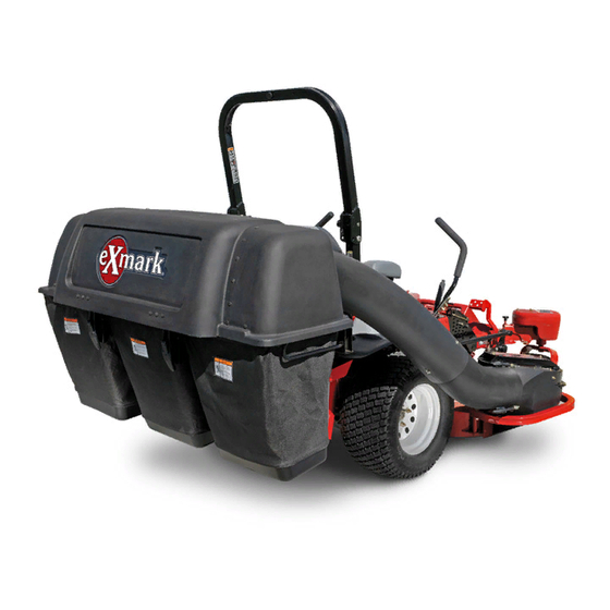
- Page 1 G032032 ULTRAVAC ® COLLECTION SYSTEM LZUVQD7, LZUVQD11 For UltraVac Serial Nos. 406,294,345 & Higher (To fit Lazer Z Units Serial Nos 790,000 & Higher) 7-Bushel–Fits units with 48 or 52 inch deck 11-Bushel–Fits units with 60 or 72 inch deck Part No.
- Page 2 State of California to cause cancer, birth defects, or other reproductive harm. Exmark reserves the right to make changes or add improvements to its products at any time without incurring any obligation to make such changes to products manufactured previously.
-
Page 3: Introduction
For complete warranty details, see All Exmark parts are thoroughly tested and inspected https://www.Exmark.com. You may also call before leaving the factory, however, attention is... -
Page 4: Table Of Contents
Contents Introduction ............3 Safety ..............5 Safety Alert Symbol ......... 5 General Safety Information ......5 Safety and Instructional Decals ....... 6 Specifications ............8 Systems ............8 Dimensions............. 8 Torque Requirements ........8 Product Overview ..........9 Operation ............... 9 Before Operation .......... -
Page 5: Safety
General Safety Information This machine is capable of amputating hands and feet and of throwing objects. Exmark designed and tested this machine to offer reasonably safe service; however, failure to comply with safety instructions may result in injury or death. -
Page 6: Safety And Instructional Decals
Exmark equipment dealer or labels. distributor or from Exmark Mfg. Co. Inc. • Replace all worn, damaged, or missing safety • Safety signs may be affixed by peeling off the signs. - Page 7 Safety decal126-4853 126-4853 1. Impeller/Rotating Blades hazard-Keep hands away from moving parts. Keep all safety devices in place and working. Do Not reach into blower unless rotation indicator has stopped. decal126-4662 126-4662 decal133-8061 133-8061 1. Warning-Read the Operator’s manual for correct quantity of counterbalance weight(s).
-
Page 8: Specifications
Specifications Specifications Overall Length: 7-Bushel Systems w/UltraVac 102.00 inches (259.1 cm) Lazer Z w/48 inch Deck Bagging System 102.00 inches (259.1 cm) Lazer Z w/52 inch Deck • Collection Hopper: 11-Bushel – Steel and Polyethylene hopper. Commercial grade, cloth mesh door with reinforced w/UltraVac bottom. -
Page 9: Product Overview
• Evaluate the terrain to determine what accessories and attachments are needed to properly and safely perform the job. Only use on machines approved by Exmark. • Wear appropriate personal protective equipment such as safety glasses, substantial slip-resistant footwear, and hearing protection. Tie back long hair and avoid loose clothing and loose jewelry which may get tangled in moving parts. -
Page 10: Pre-Start
Operation Pre-Start DANGER There are rotating blades in the blower and Make sure you understand the controls, their under the mower deck. Blade contact can locations, their functions, and their safety cause serious operator or bystander injury or requirements. even death. Ensure the blower, door mesh, tubes and hopper are •... - Page 11 Operation – Whenever you leave the mower. or truck. This will reduce the chance of rearward tip up. • Tragic accidents can occur if the operator is not alert to the presence of children. Children are Close and latch the door before continuing often attracted to the machine and the mowing mowing.
- Page 12 Operation CAUTION The deck sheave will become very hot. Touching a hot deck sheave can cause severe burns. Allow the deck sheave to cool completely before removing the belt. Pull the idler release handle and remove the belt from the upper groove of the deck sheave. Unlatch the front end of the blower.
- Page 13 Operation WARNING CAUTION An uncovered discharge opening will The exhaust diverter is hot. Touching a hot allow objects to be thrown in operator's or exhaust diverter can cause severe burns. bystander's direction. Also, contact with Allow the exhaust diverter to cool completely blade could occur.
- Page 14 Operation Remove the hairpin from the mount pin and pull WARNING the mount pin out of the frame mount barrel. Caster or toe board weights installed without Pick up the frame legs and hook the notch onto the collection system may cause loss of the lower mount bar (see Figure 10).
- Page 15 Operation the spring clevis pin from the handle link. Rotate the handle link towards the actuation arm bracket and align the holes. Insert the spring clevis pin and rotate it downward to latch it onto the handle link. g032036 Figure 13 1.
- Page 16 Operation Belt Installation: For Large Decks: For Small Decks: Pull the spring loaded idler back and slip the belt over the top deck sheave. Slip the belt over the impeller sheave on the blower. Note: It may be easier to install the belt if the belt guide is temporarily shifted to one side or temporarily removed.
- Page 17 Operation washers, and three #10-24 nyloc nuts. The screw head should be installed to the inside of the tube to provide minimum obstruction to flow. Make sure that the upper and the lower ends are oriented properly as the tubes are assembled. (Parting lines should roughly be lined up.) g009341 Figure 18...
-
Page 18: After Operation
Operation caution when positioning your hands so that you disconnect spark plug wire. Wait for all movement Do Not set them down on your hands or fingers. to stop and allow the machine to cool before adjusting, cleaning, repairing, or storing. Never allow untrained personnel to service machine. -
Page 19: Maintenance
Also original Exmark parts could lead to serious push the wire(s) aside so it does not accidentally injury or death. Unauthorized changes to the contact the spark plug(s). -
Page 20: Periodic Maintenance
Maintenance Periodic Maintenance Lubricate Grease Fittings Note: See chart for service intervals. Check Blower Stop engine, wait for all moving parts to stop, and Housing/Impeller remove key. Engage parking brake. Lubricate fittings with NLGI grade #2 Service Interval: Before each use or daily multi-purpose gun grease. -
Page 21: Check Condition Of Belt
Maintenance Check Condition of Belt Service Interval: Every 50 hours All Units Stop engine, wait for all moving parts to stop, and remove key. Engage parking brake. Inspect the belt for damage or wear. Replace belt with one of the following: Deck Part No. -
Page 22: Adjustments
Maintenance Adjustments Adjusting the Blower Drive Belt Position Read the operator’s manual for the UltraVac and mower before performing this adjustment. Make sure that you understand the controls, their locations their functions and safety requirements. Ensure the blower, belt cover, tubes and hopper are in good condition, properly attached and latched. Run the unit with the PTO and the blower engaged for two minutes. - Page 23 Maintenance 11-Bushel Unit: g009316 Figure 24 11-Bushel Unit 1. Handle Link 3. Stop 5. Latches 2. Stop Screws 4. Hinge Links Door closing: The closing of the door is controlled by the two hinge links and the two stop screws (see Figure 24).
-
Page 24: Cleaning
Maintenance Cleaning Clean Muffler and Rear Frame Area Service Interval: Before each use or daily Stop engine, wait for all moving parts to stop, and remove key. Engage parking brake. WARNING Operating engine parts, especially the muffler, become extremely hot. Severe burns can occur on contact and debris, such as leaves, grass, brush, etc. -
Page 25: Storage
Storage Storage Handle Storage When storing the 7-Bushel unit, fold the handle inward as shown in Figure 25. Remove and retain the knob and carriage bolt from the handle bracket and rotate the handle bracket and rotate the handle inward. g007995 Figure 25 7-Bushel Unit Only... -
Page 26: Troubleshooting
Troubleshooting Troubleshooting Important: It is essential that all operator safety mechanisms be connected and in proper operating condition prior to mower use. When a problem occurs, Do Not overlook the simple causes. For example: starting problems could be caused by an empty fuel tank. The following table lists some of the common causes of trouble. -
Page 27: California Proposition 65 Warning Information
While the exposure from Exmark products may be negligible or well within the “no significant risk” range, out of an abundance of caution, Exmark has elected to provide the Prop 65 warnings. Moreover, if Exmark does not provide these warnings, it could be sued by the State of California or by... - Page 28 Place Model No. and Serial No. Date Purchased Label Here (Included in the Literature Pack) or Fill in Below Model No. Serial No. ©2019 Exmark Mfg. Co., Inc. Part No. 4504-776 Rev. A 2101 Ashland Ave (402) 223-6375 Beatrice, NE 68310 Fax (402) 223-5489...