
Related Manuals for Hughes EchoStar Mobile 4500


Summary of Contents for Hughes EchoStar Mobile 4500
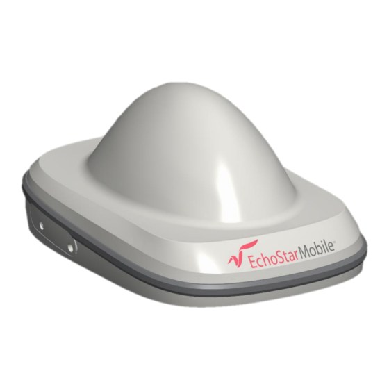
- Page 1 Hughes 4500 User Guide H62751 Revision B May 20, 2020 11717 Exploration Lane, Germantown, MD 20876 Phone (301) 428-5500 Fax (301) 428-1868/2830...
- Page 2 Hughes Network Systems, LLC has made every effort to ensure the correctness and completeness of the material in this document. Hughes Network Systems, LLC shall not be liable for errors contained herein. The information in this document is subject to change without notice. Hughes Network Systems, LLC makes no warranty of any kind with regard to this material, including, but not limited to, the implied warranties of merchantability and fitness for a particular purpose.
-
Page 3: Table Of Contents
Minimum system requirements for laptop/PC ........... 10 System Requirements to support maintenance port ......10 Additional Hardware ................10 Chapter 2 Using the Hughes 4500 ..............11 Before getting started ................11 Quick start ....................11 Connecting the terminal to the computer ..........11 Connecting by Ethernet ................ - Page 4 Contents H62751 Revision B...
-
Page 5: Understanding Safety Alert Messages
Understanding safety alert messages Safety alert messages call attention to potential safety hazards and tell you how to avoid them. These messages are identified by the signal words DANGER, WARNING, CAUTION, or NOTICE, as illustrated below. To avoid possible property damage, personal injury, or in some cases possible death, read and comply with all safety alert messages. -
Page 6: Warnings For Satellite Terminal
Avoid placing the Terminal close to cigarettes, open flames or any source of heat. Changes or modifications to the Terminal not expressly approved by Hughes Network Systems could void your authority to operate this equipment. Only use a soft damp cloth to clean the Terminal. - Page 7 Terminal. The unit does not contain consumer-serviceable components. Only qualified service personnel may install or repair equipment. Accessories: Use Hughes approved accessories only. Use of non-approved accessories may result in loss of performance, damage to the Satellite Terminal, fire, electric shock or injury.
-
Page 8: Equipment Users
Equipment users User must be a skilled person. Designated users should not be exposed to conditions that could cause pain or injury, nor intentionally caused said conditions. Understanding safety alert messages H62751 Revision B... -
Page 9: Chapter 1 Introduction
It is focused on the specific information needed to operate the Hughes 4500 terminal and to connect to the EchoStar Mobile Satellite network. If you are a first time user, you will be guided through the procedure for powering up your terminal, obtaining a GPS fix, connecting your computer to the terminal and registering with the network. -
Page 10: Minimum System Requirements For Laptop/Pc
• Microsoft Windows 7 • Microsoft Windows 10 Additional Hardware Please refer to the Hughes catalog and pricelist for the purchase of any optional additional hardware items. Table 1: Additional Hardware Items from the Hughes catalog Item Part Number Specifications... -
Page 11: Using The Hughes 4500
Figure 2: Inserting the USIM card Quick start The Hughes 4500 terminal must first obtain a GPS fix by positioning it with an open view of the sky. The GPS fix is acquired by the time the terminal is fully booted up. - Page 12 Chapter 2 • Using the Hughes 4500 H62751 Revision B...
-
Page 13: Chapter 3 Using The Web Ui
Using the Web UI Accessing the Web UI The Hughes 4500 includes an internal Web User Interface (Web UI). To access the Web UI, open your favourite web browser and type in the internal IP address of the terminal. If you are using a: •... -
Page 14: Connections
Once connected to the network, the Terminal Status page will show that the UT is registered with the network. In the middle of the Terminal Status page it will show that the “Shared Connection” is established along with the TE’s local IP address. -
Page 15: Settings Page
• Port Forwarding • Remote Management General setup This subpage allows the user to configure general parameters of the Hughes 4500 Terminal. A description of each item is as follows: • Language – The user can choose between the different language options by clicking the drop-down arrow, select the language and then click the Apply Changes button. -
Page 16: Ip Address/Dhcp Settings
IP Address/DHCP Settings • Terminal Local IP Address – This section allows the user to change the local IP address of the terminal from the default Ethernet IP address: 192.168.128.100. All four octets are available to change. Once the local IP address is changed on this page and applied, the first 3 octets of the DHCP address range will also change automatically. -
Page 17: Ethernet Security
Ethernet security The Ethernet Security page allows the user to enable Ethernet MAC Address Filtering. • Ethernet MAC Address Filtering – User can select any detected device and add the MAC address to the Allowed MAC Addresses field to the left. The user can also manually add a MAC address in the box at the bottom of the page, then add it to the Allowed MAC Address field. - Page 18 • SIM Lock PIN – Use up to 8 digits to lock the terminal to the current SIM card. The SIM Lock PIN code will have to be entered any time a different SIM card is used with the terminal. •...
-
Page 19: Apn Profiles
Figure 9: Change SIM PIN Settings screen Figure 10: Create Administration Password screen APN Profiles • Profile Settings – This section allows the user to choose the Default APN Profile, selecting from the drop-down menu the APN Profile and clicking to Apply Changes. -
Page 20: Connection Profiles
Connection Profiles This page allows to configure the user data connections (Shared and Dedicated) choosing the APN Profile and the Activation Method. • Connection Watchdog – This section allows the user to enable the Connection Watchdog feature. When the feature is enabled, the traffic on the space link is monitored and the terminal will reboot if there is no traffic detected during the monitoring period. -
Page 21: Outbound Filters
• Connection Profile - Shared Connection – This section allows the user to define the APN Profile of the Shared Connection. And how the Shared Connection is established. The user can select the options available from the drop-down menu and click the Save button. —... - Page 22 — Rule Name — Rule Precedence — Rule Action • Block • Allow — Rule Enabled At least one of the following optional parameters must be provided: • Source Address • Destination Address • Destination Port Low • Destination Port High •...
-
Page 23: Port Forwarding
Port forwarding The Port Forwarding page allows the user to enable and setup a DMZ IP address and specific Port Forwarding rules. If both DMZ and Port Forwarding rules are enabled, then the Port Forwarding rules take precedence and all other traffic is forwarded to the DMZ IP address. - Page 24 • Port Triggering – This allows for outgoing traffic to automatically configure port forwarding to the originating device. The port forwarding rule is active for 120 seconds after the trigger event occurred. The Port Triggering parameters to be configured are: —...
-
Page 25: Remote Management
Remote management This page allows the user to manage the Remote Management feature applying the changes in the sections here below: • Remote Management – This function allows the terminal to be managed remotely over the satellite connection. — Add Management Address – This section allows the user to configure a list of IP Addresses that can send remote commands. -
Page 26: Usage Statistics
Click the Change Settings button to modify the Remote Management Settings. The user will need to enter the Current Remote Password in order to change any parameters, as shown in the image below. Figure 19: Change Remote Management Settings screen Usage statistics This page shows the statistics of data transmitted and received on connections in megabytes. -
Page 27: Support Page
“eml_4500_5.x.x.x.hif”, where the X’s correspond to the Software release number. The EML Terminal Software Package contains all necessary images for the Hughes 4500 product. The terminal automatically detects the Software images which apply to the product after loading the Software Package into the terminal. - Page 28 To upgrade the Terminal Software, follow these steps: 1. Store the Terminal Software Package on the local drive of a computer attached to the terminal. 2. Select the “Browse” button. 3. Navigate to the storage location of the Software Package, select the file and click “Open.”...
- Page 29 • Modem Diagnostics – This section provides access to information that may be useful to aid in troubleshooting. Follow instructions of technical support personnel to obtain diagnostics information if needed. Figure 23: Modem Diagnostic screen Chapter 3 • Using the Web UI H62751 Revision B...
- Page 30 Chapter 3 • Using the Web UI H62751 Revision B...
-
Page 31: Chapter 4 Troubleshooting
Chapter 4 Troubleshooting Table 2: Troubleshooting Problem Possible cause Possible solution Terminal will not turn on Remote switch is off Connect and turn on the remote switch signal Cannot get USIM card to lock USIM is not correctly oriented for Ensure the USIM is oriented as into position insertion... - Page 32 Chapter 4 • Troubleshooting H62751 Revision B...
-
Page 33: Technical Specifications
Chapter 5 Technical specifications Table 3: Technical Specifications Item Specifications Weight 1.4 kg Dimensions 248 mm x 178 mm x 115 mm Humidity 95% RH at 40 °C Power, Max 16 W (when transmitting) Water/Dust IP-67 Operating Temperature -25 °C to +65 °C Storage Temperature -40 °C to +80 °C External Power Supply... - Page 34 Acronym Definition Status Flag Physical Layer status flag Time Offset Received burst time offset Transmit Statistics ARFCN Absolute Radio Frequency Channel Number Burst MC S Burst Modulation and Coding Scheme Burst Type Physical Layer internal burst type Frame Physical Layer internal frame number Power Attenuation Notification PD CW Physical Layer internal Power Detector Code...
-
Page 35: Definitions And Acronyms
Definitions and acronyms Table 5: Definitions and Acronyms Acronym Definition Access Point Name Common Air Interface EchoStar Mobile Limited Global Positioning System Hardware ICCID Integrated Circuit Card ID Identifier IGMP Internet Group Management Protocol IMEI International Mobile Equipment Identity IMPI IP Multimedia Private Identity IMPU IP Multimedia Public Identity... - Page 36 Definitions and acronyms H62751 Revision B...