Advertisement
Quick Links
You will need a Phillips Head Screw Driver and a Rubber Mallet to Assemble.
Hardware :
A: Flat Bracket(2) • B: Small Screws(48) • C: Cam Pins(10) • D: Double Sided Cam Pins(2)
E: Cam Locks(12) • F: Dowel Rods(8) • G: Corner Bracket(6)
B
A
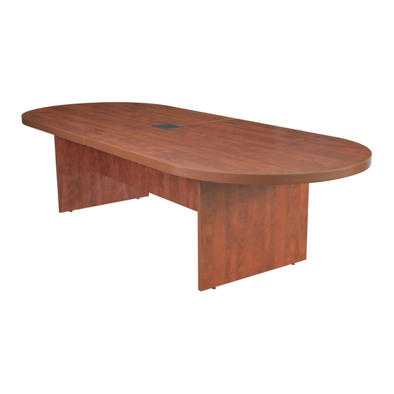
Parts :
H: Top(2) • I: Stringer • J: Leg(2)
H
STEP 1 : Lay one top(H) down cam locks(E) facing up and
insert 2 double cam pins(D) into locks(E) and tighten.
H
IMPORTANT NOTICE:
● Place all wooden parts on a clean and smooth surface such as a rug or carpet to avoid the parts from being scratched.
● Check to be sure that you have all parts and hardware.
● Remove all wrapping materials, including staples & packing straps before you start to assemble.
● Do not tighten all screws/bolts until completely assembled.
● Keep all hardware parts out of reach of children.
LCTRT12047, VCTRT12047 - INSTRUCTIONS
You will need 2 person(s) for this assembly.
C
D
E
I
F
G
J
STEP 2 : Lay second table top(H) down and insert opposite
side of double cam pins(D) into locks(E) and tighten.
H
H
Advertisement

Related Manuals for Regency Legacy LCTRT12047


Summary of Contents for Regency Legacy LCTRT12047
- Page 1 LCTRT12047, VCTRT12047 - INSTRUCTIONS You will need 2 person(s) for this assembly. You will need a Phillips Head Screw Driver and a Rubber Mallet to Assemble. Hardware : A: Flat Bracket(2) • B: Small Screws(48) • C: Cam Pins(10) • D: Double Sided Cam Pins(2) E: Cam Locks(12) •...
- Page 2 LCTRT12047, VCTRT12047 - INSTRUCTIONS You will need 2 person(s) for this assembly. You will need a Phillips Head Screw Driver and a Rubber Mallet to Assemble. STEP 3 : 3 screws on each side of gap) Also insert 6 cam pins(C) and 2 dowel rods(F) to bottom of table top. STEP 4 : Insert 2 Cam Pins(C) and 2 Dowel rods(F) in each STEP 5 : Lay one leg(J) down with cam pins(C) and dowel leg(J).
- Page 3 LCTRT12047, VCTRT12047 - INSTRUCTIONS You will need 2 person(s) for this assembly. You will need a Phillips Head Screw Driver and a Rubber Mallet to Assemble. STEP 6 :Connect second leg(J) to the opposite end of the STEP 7 : Attach 4 corner brackets(G) with 6 screws(B) stringer(I) by inserting cam pins(C) into locks(E) and tighten- each bracket to the 4 corners where the legs(J) meet the stringer(I).