
Related Manuals for Planet ISW-504PS


Summary of Contents for Planet ISW-504PS
- Page 1 User's Manual ISW-504PS / ISW-514PS ISW-514PS15 / ISW-514PSF 5-Port 10/100Mbps with 4-Port PoE Web Smart Industrial Ethernet Switch...
- Page 2 PLANET has made every effort to ensure that this User’s Manual is accurate; PLANET disclaims liability for any inaccuracies or omissions that may have occurred.
- Page 3 Do not dispose of WEEE as unsorted municipal waste and have to collect such WEEE separately. Revision PLANET 5-Port 10/100Mbps with 4-Port PoE Web Smart Industrial Ethernet Switch User's Manual FOR MODELS: ISW-504PS / ISW-514PS / ISW-514PS15 / ISW-514PSF REVISION: 1.0 (JULY.2010) Part No.: EM-ISW-5xxPS Series_v1.0 (2080-AH0240-000)
-
Page 4: Table Of Contents
VERVIEW 3.2 R ............................24 EQUIREMENTS 3.3 M ........................... 24 ANAGEMENT ETHOD 3.3.1 Web Management........................... 24 3.3.2 PLANET Smart Discovery Utility..................... 27 4. WEB CONFIGURATION ....................29 4.1 M ............................. 29 4.2 W ............................. 30 ANEL 4.3 S ..............................31... - Page 5 User’s Manual 4.3.1 System Information ......................... 32 4.3.2 IP Configuration ..........................33 4.3.3 Password Setting ..........................34 4.3.4 Firmware Upgrade .......................... 34 4.3.5 Configuration Setting ........................38 4.3.6 Configuration Backup........................40 4.3.7 Managed IP............................. 41 4.3.8 Fault Relay Alarm ........................... 41 4.3.9 Alert Trap Configuration........................
- Page 6 User’s Manual 6. POWER OVER ETHERNET OVERVIEW..............79 7. THE POE PROVISION PROCESS ................82 7.1 L ............................82 ETECTION 7.2 C ............................82 LASSIFICATION 7.3 S ..............................83 TART 7.4 O ............................. 83 PERATION 7.5 P ......................83 OWER ISCONNECTION CENARIOS 8.
-
Page 7: Introduction
Ethernet, Fast Ethernet workgroups and networks. With 4 PoE interfaces, the ISW-504PS / ISW-514PS series is ideal for small business and workgroups requiring to deploy the PoE for the wireless access points, IP-based surveillance camera or IP phones in any places easily, efficiently and cost effective. -
Page 8: Features
Firmware upgrade through Web interface SNMP Trap for alarm notification of events VLAN and QoS configuration PLANET Smart Discovery utility automatically finds PLANTE devices on the network Switching Complies with IEEE 802.3 10Base-T, IEEE 802.3u 100Base-TX / 100Base-FX Ethernet standard... -
Page 9: Specification
24 or 48V DC, redundant power with polarity reverse protect function Supports EFT protection 6000V DC for power line Supports 6000V DC Ethernet ESD protection -10 to 60 Degree C operation temperature 1.4 Specification Model ISW-504PS ISW-514PS ISW-514PS15 ISW-514PSF Hardware Specification 10/100Base-TX Ports... - Page 10 User’s Manual 10/100Base-TX: Cat. 3, 4, 5, 5e, 6 UTP cable (100meters max.) EIA/TIA-568 100-ohm STP (100meters max.) Multi-mode optic Network Cables fiber 62.5/125μm, Multi-mode optic fiber Single-mode optic 50/125μm 62.5/125μm, fiber 9/125μm (15km Single-mode optic 50/125μm (2km max.). max.). fiber 9/125μm (Vary on SFP Module)
-
Page 11: Product Application
User’s Manual 1.5 Product Application As a department / workgroup PoE Switch Providing up to 4 PoE, in-line power interface, the Industrial PoE Switch can easily build a power central-controlled IP phone system, IP Camera system, AP group for the enterprise. For instance, 4 camera / AP can be easily installed around the corner in the company for surveillance demands or build a wireless roaming environment in the office. -
Page 12: Installation
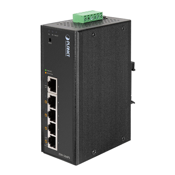
2. INSTALLATION 2.1 Hardware Description The ISW-504PS / ISW-514PS series provide two different running speeds – 10Mbps, 100Mbps in the same Switch and automatically distinguish the speed of incoming connection. This section describes the hardware features of ISW-504PS / ISW-514PS series. For easier management and control of the Switch, familiarize yourself with its display indicators, and ports. -
Page 13: Front Panel
Figure 2-1 shows a front panel of Industrial PoE Switch. Figure 2-1 ISW-504PS and ISW-514PS / ISW-514PS15 and ISW-514PF Switch front panel ■ Reset Button At the left of front panel, the reset button is designed for reboot the Industrial PoE Switch without turn off and on the power, also can reset the Industrial PoE Switch to factory default mode. -
Page 14: Led Indicators
User’s Manual Figure 2-2 Reset button of Industrial PoE Switch Press the RESET button once. The Industrial PoE Switch will reboot automatically. Press the RESET button for 5 seconds. The Industrial PoE Switch will back to the factory default mode; the entire configuration will be erased. 2.1.3 LED Indicators System Color... -
Page 15: Switch Upper Panel
User’s Manual PoE Port Color Function PoE In Use Orange Indicate the port is providing 48V DC in-line power. (1-4 ports) 2.1.4 Switch Upper Panel The Upper Panel of the Industrial PoE Switch indicates a DC inlet power socket and consist one terminal block connector within 6-contacts. -
Page 16: Install The Switch
User’s Manual 2.2 Install the switch This section describes how to install your Managed Industrial Switch and make connections to the Managed Industrial Switch. Please read the following topics and perform the procedures in the order being presented. To install your switch on a desktop or shelf, simply complete the following steps. - Page 17 User’s Manual Step 1: Screw the DIN-Rail on the Industrial PoE Switch. Step 2: Lightly press the button of DIN-Rail into the track. -17 -...
- Page 18 User’s Manual Step 3: Check the DIN-Rail is tightly on the track. Please refer to following procedures to remove the Industrial PoE Switch from the track. Step 5: Lightly press the button of DIN-Rail for remove it from the track. -18 -...
-
Page 19: Wall Mount Plate Mounting
User’s Manual 2.2.3 Wall Mount Plate Mounting To install the Industrial PoE Switch on the wall. Please follow the instructions below. Step 1: Remove the DIN-Rail from the Industrial PoE Switch. Use the screwdriver to loose the screws and remove the DIN-Rail. -
Page 20: Wiring The Fault Alarm Contact
User’s Manual Power 1 Fault Power 2 Figure 2-4: 6-Contacts of Terminal Block Connector 1. The wire gauge for the terminal block should be in the range between 12 ~ 24 AWG. Power Notice: 2. Performing any of the procedures like inserting the wires or tighten the wire-clamp screws. Ensure the power is OFF to prevent to get an electric shock. -
Page 21: Cabling
The 10/100Mbps RJ-45 ports come with Auto-Negotiation capability. Users only need to plug in working network device into one of the 10/100Mbps RJ-45 ports. The ISW-504PS / ISW-514PS series will automatically run in 10Mbps or 100Mbps after the negotiation with the connected device. The ISW-514PS has one 100Base-FX SC Interface (Multi-mode, 50/125μm or 62.5/125μm fiber cable and the available distance is 2km). - Page 22 User’s Manual Figure 2-6 Plug-in the SFP transceiver Before connect the other switches, workstation or Media Converter. Make sure both side of the SFP transceiver are with the same media type or WDM pair, for example: 100Base-FX to 100Base-FX, 100Base-BX20-U to 100Base-BX20-D. Check the fiber-optic cable type match the SFP transceiver model.
-
Page 23: Remove The Module
User’s Manual 2.5.2 Remove the module Make sure there is no network activity by consult or check with the network administrator. Or through the management interface of the switch/converter (if available) to disable the port in advance. Remove the Fiber Optic Cable gently. Turn the handle of the MFB module to horizontal. -
Page 24: Management
User’s Manual 3 MANAGEMENT This chapter describes how to manage the Industrial PoE Switch Topics include: - Overview - Management method - Logging on to the Industrial PoE Switch 3.1 Overview The Industrial PoE Switch provides a user-friendly, Web interface. Using this interface, you can perform various device configuration and management activities, including: System Power over Ethernet... - Page 25 Web interface. Figure 3-1 Web Management over Ethernet When the following login screen appears, please enter Planet’s default Username "admin" and Password “admin” to login the main screen of Industrial PoE Switch. The login screen in Figure 3-2 appears.
- Page 26 User’s Manual Figure 3-2 Web Login screen For security reason, please changes and remembers the new password after this first setup. Only accept command in lowercase letter under WEB interface. -26 -...
-
Page 27: Planet Smart Discovery Utility
User’s Manual 3.3.2 PLANET Smart Discovery Utility For easily list the Industrial PoE Switch in your Ethernet environment, the Planet Smart Discovery Utility from user’s manual CD-ROM is an ideal solution. The following install instructions guiding you for run the Planet Smart Discovery Utility. - Page 28 To click the “Control Packet Force Broadcast” function, it can allow assign new setting value to the Switch under different IP subnet address. “Connect to Device” button, the Web login window screen will appear, just like Figure 3-2. Press “Exit” button to shutdown the Planet Smart Discovery Utility. -28 -...
-
Page 29: Web Configuration
User’s Manual 4. WEB CONFIGURATION The Industrial PoE Switch provides Web interface for PoE smart function configuration and make the Industrial PoE Switch operate more effectively - They can configure through the Web Browser and the network administrator can manage and monitor the Industrial PoE Switch from the local LAN. -
Page 30: Web Panel
User’s Manual in section 4.8. PoE Configuration Provide PoE Management configuration of Switch. Explained in section 4.9. Logout: Provide Logout function of Switch. Table 4-1 Descriptions of the Function items 4.2 Web Panel On the left of the Web management page, the active panel displays the link status of management port and PoE ports. Color Function Indicate the power 1 has... -
Page 31: System
User’s Manual 4.3 System The System function allows viewing System information, IP Configuration, Password Setting and etc. As shown in Figure 4-3 and description on Table 4-3 Figure 4-3 System Screen The page includes the following information: Object Description Display the MAC address, Software Version, Hardware Version, IP address, Subnet System Information Mask and Gateway. -
Page 32: System Information
User’s Manual 4.3.1 System Information The System information will show the system MAC Address, Software Version, Hardware Version, IP Address, Subnet Mask and Gateway. As shown in Figure 4-4 and description on Table 4-4 Figure 4-4 System Information screen The page includes the following fields: Object Description Specifies the Switch MAC address. -
Page 33: Ip Configuration
User’s Manual 4.3.2 IP Configuration This section provides DHCP Client, change the IP Address, Subnet Mask, Gateway and Description. As shown in Figure and description on Table 4-5 Figure 4-5 IP Configuration Screen The page includes the following configurable data: Object Description Choose what the Switch should do following power-up: transmit a DHCP request, or manual... -
Page 34: Password Setting
User’s Manual 4.3.3 Password Setting This section provides password change Configuration of Industrial PoE Switch, please input the old password in “Old Password” space and input the new password in “New Password” space then input the new password again in “Confirm”... - Page 35 User’s Manual Figure 4-7 Firmware Upgrade screen Please wait for two seconds and the page will turn to next firmware upgrade web page. As shown in Figure 4-8. Figure 4-8 Firmware Upgrade screen Please press “Browser” to locate the latest firmware of Switch that deposit in your PC and press “Upgrade” to start the firmware upgrade process.
- Page 36 User’s Manual Figure 4-9 Firmware Upgrade screen(1) Figure 4-10 Firmware Upgrade screen (2) -36 -...
- Page 37 Or the system won’t apply the new firmware. Users have to repeat the firmware upgrade processes again. Do not use Firefox or Windows Vista platform for ISW-504PS / ISW-514PS series firmware upgrade or it might cause the firmware upgrade fail. Because of the short “HTTP respond time” for Firefox and Windows Vista.
-
Page 38: Configuration Setting
User’s Manual 4.3.5 Configuration Setting This function allows backup and restore the current configuration of Industrial PoE Switch, or reset the Industrial PoE Switch to factory default. The description of the three items as follow and as shown in Figure 4-11. - Page 39 User’s Manual If finish the Backup and work successfully, it will show a message that tells you it done. As shown in Figure 4-13. Figure 4-13 Configuration backup successes screen Restore The Industrial PoE Switch will restore to previous backup/saved configuration while the “Restore” button be pressed. And please note that once the Restore button be pressed, Web interface will disconnected for a while.
-
Page 40: Configuration Backup
User’s Manual Figure 4-16 Factory Reset screen 4.3.6 Configuration Backup This function allows downloading the current configuration as a file. The filename extension will be “cfg” file. If already downloads 3 different setting of files as file 1, file 2 and file 3. As showed in Figure 4-17. -
Page 41: Managed Ip
User’s Manual 4.3.7 Managed IP The function allows setting 5 specific IP address to access the Industrial PoE Switch. As shown in Figure 4-18. Figure 4-18 Managed IP Screen 4.3.8 Fault Relay Alarm This Function allows controlling the Power Failure. If the terminal block connector has connected the fault alarm contacts (3 &... -
Page 42: Alert Trap Configuration
User’s Manual 4.3.9 Alert Trap Configuration This function displays the Industrial PoE Switch alert trap configuration; include “Enable” or “Disable” the trap mode and set the alert IP address. As shown in Figure 4-20 and description on Table 4-7. Figure 4-20 Alert Trap Configuration screen Object Description Trap mode... -
Page 43: System Reboot
User’s Manual 4.3.10 System Reboot This section provides reboot the Industrial PoE Switch, after choose this function and the following screen appears in Figure 4-21. Please press “OK” button to take effect and the Industrial PoE Switch will reboot and ask you to re-login web interface with correct user name “admin”... -
Page 44: Port Management
User’s Manual 4.4 Port Management In this chapter, there are three sub-functions can be configure and monitor about network interfaces: Port Configuration Port Status Port Security 4.4.1 Port Configuration This section introduces detail settings of per port of Industrial PoE Switch as shown in Figure 4-24 Table 4-8 describes... -
Page 45: Port Status
User’s Manual • No Limit • 1M • 128K • 2M • 256K • 4M • 512K • 8M The value of outbound traffic limitation in kilobit-per-second (kbps). Egress Shaping Default : No Limit • No Limit • 1M • 128K •... -
Page 46: Port Security
User’s Manual 4.4.3 Port Security The Layer 2 MAC address learning function can be per-port disable for security management purposes. When the port is in security mode, the port will be "locked" without permission of address learning. For Example: 1. Enable the Port 1 Security and the port will record the first receiving packet's source MAC address as a "Security MAC address ". -
Page 47: Vlan
Layer 2 switch. However, all the network devices are still plug into the same switch physically. The ISW-504PS / ISW-514PS series Ethernet Switch supports 802.1Q (tagged-based) and Port-Base VLAN setting in web management page. The default configuration of VLAN setting is “Disable”. - Page 48 User’s Manual carried across Ethernet backbones), and 12 bits of VLAN ID (VID). The 3 bits of user priority are used by 802.1p. The VID is the VLAN identifier and is used by the 802.1Q standard. Because the VID is 12 bits long, 4094 unique VLAN can be identified.
- Page 49 User’s Manual A switch port can have only one PVID, but can have as many VID as the switch has memory in its VLAN table to store them. Because some devices on a network may be tag-unaware, a decision must be made at each port on a tag-aware device before packets are transmitted –...
-
Page 50: Vlan Group
User’s Manual 4.5.1 VLAN Group The VLAN Group page contains fields for managing VLAN mode of the Industrial PoE Switch and setting ports that are part of a VLAN. The port default VLAN ID (PVID) is configured on the VLAN Port Configuration page. All untagged packets arriving to the device are tagged by the ports PVID. - Page 51 User’s Manual Figure 4-28 VLAN Group – Port-Based VLAN screen When Port-Based VLAN mode is selected, the displayed page includes the following configurable data. Description on Table 4-10 Object Description There’re three VLAN mode support – 802.1Q VLAN, Port-Bas VLAN and No VLAN Type VLAN.
- Page 52 User’s Manual 4.5.1.2 IEEE 802.1Q VLAN This function group individual ports into a small “Virtual” network of their own to be independent of the other ports. By setting the VLAN Type with 802.1Q, IEEE 802.1Q tag-based VLAN is enabled. VLAN classification is the first step before VLAN table lookup.
- Page 53 User’s Manual • Disable - Forbidden ports are not included in the VLAN • VLAN Group The VLAN entry index. Select the column to specify the VLAN group for VLAN member ports configure. The Switch supports up to 16 active VLAN groups. •...
-
Page 54: Vlan Per Port Setting
User’s Manual 4.5.2 VLAN Per Port Setting The Industrial PoE Switch inserts or removes a tag of frame if Tag / UnTag function is enabled. The operation is illustrated as follows. As shown in Figure 4-30 and description on Table 4-12. Understand nomenclature of the 802.1Q VLAN aware Switch Tagging and Untagging Every port on an 802.1Q compliant switch can be configured as tagging or untagging. - Page 55 User’s Manual The page includes the following fields: Object Description Indicate the physical interface for which you want to display or configure data. Port Link Type Allow 802.1Q Untagged or Tagged VLAN for selected port. When adding a VLAN to selected port, it tells the switch whether to keep or remove the tag from a frame on egress.
-
Page 56: Vlan Setting Example
User’s Manual 4.5.3 VLAN setting example: 4.5.3.1 Two separate 802.1Q VLAN The diagram shows how the Industrial PoE Switch handle Tagged and Untagged traffic flow for two VLANs. VLAN Group 2 and VLAN Group 3 are separated VLAN. Each VLAN isolate network traffic so only members of the VLAN receive traffic from the same VLAN members. - Page 57 User’s Manual Tagged packet entering VLAN 2 While [PC-2] transmit a tagged packet with VLAN Tag=2 enters Port-2, [PC-1] will received the packet through Port-1. While the packet leaves Port-1, it will be stripped away it tag becoming an untagged packet. Untagged packet entering VLAN 3 While [PC-3] transmit an untagged packet enters Port-3, the switch will tag it with a VLAN Tag=3.
- Page 58 User’s Manual Figure 4-32 Assign VLAN 2 Group members screen Remember to remove the Port 1 – Port 4 from VLAN 1 membership, since the Port 1 – Port 4 had been assigned to VLAN 2 and VLAN 3. It’s import to remove the VLAN members from VLAN 1 configuration. Or the ports would become overlap setting.
- Page 59 User’s Manual Figure 4-33 Port 1-Port 5 VLAN Configuration 4.5.3.2 Two VLANs with overlap area Follow the example of 4.5.3.1. There’re two exist separate VLANs – VLAN 2 and VLAN 3, and the PCs of each VLANs are not able to access each other of different VLANs. But they all need to access with the same server. The screen in Figure 4-34 appear.
- Page 60 User’s Manual Specify Port-5 on the device to connect to the server. Assign Port-5 to both VLAN 2 and VLAN 3 at the VLAN Member configuration page. The screen in Figure 4-35 appears. Figure 4-35 VLAN overlap port setting Define a VLAN 1 as a “Public Area” that overlapping with both VLAN 2 members and VLAN 3 members. -60 -...
- Page 61 User’s Manual Figure 4-36 VLAN 1 – The public area member assigning Setup Port-5 with “PVID=1” at VLAN per Port Configuration page. The screen in Figure 4-37 appears. Figure 4-37 Setup Port-5 with PVID-1 That is, although the Port-4, are also belonging to VLAN 2 members: Port-1 to Port-2 VLAN 3 members: Port-3 to VLAN 1.
- Page 62 User’s Manual 4.5.3.3 Port-based VLAN setting example: VLAN scenario is the file server port for all the workstations Port-5 is different devices that do not need to see each other Port-1 Port-4 Setup steps 1. Port Setting 1.1 Assign VLAN 2 for the second VLAN group with Port-1 Port-5 1.2 Repeat the same steps for Port-2 to Port-7.
-
Page 63: Quality Of Service
User’s Manual 4.6 Quality of Service Quality of Service (QoS) is an advanced traffic prioritization feature that allows you to establish control over network traffic. QoS enables you to assign various grades of network service to different types of traffic, such as multi-media, video, protocol-specific, time critical, and file-backup traffic. -
Page 64: 802.1P Tag Priority Mode
User’s Manual Figure 4-39 Quality of Service screen 4.6.1 802.1p Tag Priority Mode QoS settings allow customization of packet priority in order to facilitate delivery of data traffic that might be affected by latency problems. When 802.1p Tag Priority is applied, the Industrial PoE Switch recognizes 802.1Q VLAN tag packets and extracts the VLAN tagged packets with User Priority value. - Page 65 User’s Manual Figure 4-41 QoS - 802.1p Tag Priority screen The page includes the following fields: • Object • Description The draw menu allows customization of QoS mode for Traffic classifiers. • QoS Mode • 802.1p Tag Priority • IP DSCP •...
-
Page 66: Dscp Qos Mode
User’s Manual 4.6.2 DSCP QoS Mode DiffServ Code Point (DSCP) - is the traffic prioritization bits within an IP header that are encoded by certain applications and/or devices to indicate the level of service required by the packet across a network. 4 bit 4 bit 6 bit... - Page 67 User’s Manual Figure 4-43 DSCP QoS Configuration screen The page includes the following fields: • Object • Description The draw menu allows customization of QoS mode for Traffic classifiers. • QoS Mode • 802.1p Tag Priority • IP DSCP • Port-Base Priority Weighted Round Robin ratio setting of priority queue.
- Page 68 User’s Manual DSCP are defined in RFC-2597 for classifying traffic into different service classes. The Industrial PoE Switch extracts the code point value of the DS field from IPv4 packets and identifies the priority of the incoming IP packets following the definitions listed below: Suggest High Priority IP DSCP Value AF11...
-
Page 69: Port-Based Priority Mode
User’s Manual 4.6.3 Port-Based Priority Mode When Port-Based priority is applied, any packets received from a high priority port will be treated as a high priority packet. Select the QoS mode to Port-Based Priority, the Port ID to queue mapping configuration page appears, as the Figure 4-44 shows. -
Page 70: Storm Control
User’s Manual 4.7 Storm Control The Storm Control function enables each port to drop broadcast packets (Destination MAC Address is “FF-FF-FF-FF-FF-FF) after a continuous received broadcast packets counter count of the defined value of rate threshold. This function is to control the Broadcast Storm and Multicast storm packet on each port. The screen Figure 4-45 appears. -
Page 71: Misc Configuration
Table 4-17 Descriptions of the Storm Control 4.8 Misc Configuration This section provides Misc Configuration of ISW-504PS / ISW-514PS series, it allows configuring Flow Control, MAC Address Aging time, Backpressure, Link down power saving and Congested Port Drop for the Industrial PoE Switch. - Page 72 User’s Manual saving • Disable – Disable link down power saving mode. When the Link down power saving mode is enabled, the system power consumption of this PoE Switch will reduce from 5.6Watts to 4.3watts. • Aging time Enable or Disable MAC table aging time function. An address tag in hashing table will be removed if this function is turned on and its aging timer expires.
-
Page 73: Poe Configuration
User’s Manual 4.9 PoE Configuration Providing up to 4 PoE, in-line power interface, the Industrial PoE Switch can easily build a power central-controlled IP phone system, IP Camera system, AP group for the enterprise. For instance, 4 camera / AP can be easily installed around the corner in the company for surveillance demands or build a wireless roaming environment in the office. - Page 74 User’s Manual This section provides PoE (Power over Ethernet) Configuration and PoE output status of Industrial PoE Switch, screen in Figure 4-47 appears. Figure 4-47 PoE Configuration screen Object Description Allow to configure power limit mode of Web Smart Device. It can choose : Power limit mode Port Priority Deliver PoE power by port priority setting Total Limit.
- Page 75 User’s Manual It shows the PoE device current Amp. Current(mA) It shows the PoE device current watt. Consumption [W] It can limit the port PoE supply watts. Power Limit Per port maximum value must less 15.4w, total ports values must less than the Power Reservation value.
-
Page 76: Logout
User’s Manual 4.10 Logout Press this function; the Web interface will go back to login screen. The screens in Figure 4-48 Figure 4-49 appears. Figure 4-48 Logout dialogues screen Figure 4-49 Web Login screen -76 -... -
Page 77: Switch Operation
User’s Manual 5. SWITCH OPERATION 5.1 Address Table The Switch is implemented with an address table. This address table composed of many entries. Each entry is used to store the address information of some node in network, including MAC address, port no, etc. This information comes from the learning process of Industrial Ethernet Switch. -
Page 78: Auto-Negotiation
User’s Manual The Industrial Switch performs "Store and forward" therefore, no error packets occur. More reliably, it reduces the re-transmission rate. No packet loss will occur. 5.5 Auto-Negotiation The STP ports on the Industrial PoE Switch have built-in "Auto-negotiation". This technology automatically sets the best possible bandwidth when a connection is established with another network device (usually at Power On or Reset). -
Page 79: Power Over Ethernet Overview
User’s Manual 6. POWER OVER ETHERNET OVERVIEW What is PoE? Based on the global standard IEEE 802.3af, PoE is a technology for wired Ethernet, the most widely installed local area network technology adopted today. PoE allows the electrical power necessary for the operation of each end-device to be carried by data cables rather than by separate power cords. - Page 80 User’s Manual Figure 1 - Power Supplied over the Spare Pins The data pairs are used. Since Ethernet pairs are transformer coupled at each end, it is possible to apply DC power to the center tap of the isolation transformer without upsetting the data transfer. In this mode of operation the pair on pins 3 and 6 and the pair on pins 1 and 2 can be of either polarity.
- Page 81 User’s Manual References: IEEE Std 802.3af-2003 (Amendment to IEEE Std 802.3-2002, including IEEE Std 802.3ae-2002), 2003 Page(s):0_1-121 White Paper on Power over Ethernet (IEEE802.3af) http://www.poweroverethernet.com/articles.php?article_id=52 Microsemi /PowerDsine http://www.microsemi.com/PowerDsine/ Linear Tech http://www.linear.com/ -81 -...
-
Page 82: The Poe Provision Process
User’s Manual 7. THE POE PROVISION PROCESS While adding PoE support to networked devices is relatively painless, it should be realized that power cannot simply be transferred over existing CAT-5 cables. Without proper preparation, doing so may result in damage to devices that are not designed to support provision of power over their network interfaces. -
Page 83: Start-Up
User’s Manual Classifying a PD according to its power consumption may assist a PoE system in optimizing its power distribution. Such a system typically suffers from lack of power resources, so that efficient power management based on classification results may reduce total system costs. 7.3 Start-up Once line detection and optional classification stages are completed, the PSE must switch from low voltage to its full voltage capacity (44-57 Volts) over a minimal amount of time (above 15 microseconds). - Page 84 User’s Manual This method is based on the fact that when a valid PD is connected to a port, the AC impedance measured on its terminals is significantly lower than in the case of an open port (disconnected PD). AC Disconnect detection involves the induction of low AC signal in addition to the 48 VDC operating voltage. The returned AC signal amplitude is monitored by the PSE at the port terminals.
-
Page 85: Troubleshooting
Solution: 1. Please check the cable type of the connection from ISW-504PS / ISW-514P series (port 1 to port 4) to the other end. The cable should be an 8-wire UTP, Category 5 or above, EIA568 cable within 100 meters. A cable with only 4-wire, short loop or over 100 meters, all will affect the power supply. -
Page 86: Appendix A Networking Connection
User’s Manual APPENDIX A NETWORKING CONNECTION A.1 DATA OUT PoE Switch RJ-45 Port Pin Assignments (Port 1 to Port-4) PIN NO RJ-45 SIGNAL ASSIGNMENT • Output Transmit Data + • Power + • Output Transmit Data – • Power + •... - Page 87 User’s Manual The standard cable, RJ-45 pin assignment The standard RJ-45 receptacle/connector There are 8 wires on a standard UTP/STP cable and each wire is color-coded. The following shows the pin allocation and color of straight cable and crossover cable connection: Straight Cable SIDE 1 SIDE2...
-
Page 88: Power Over Ethernet Compatibility Test
User’s Manual APPENDIX B B.1 Power over Ethernet Compatibility test PoE Output Note [PLANET POE-151S-12V] + [PLANET ICA-500] 9.6W [PLANET POE-151S-12V] + PLANET ICA310 6.4W Standby [PLANET POE-152S-12V] + [PLANET ICA-500] 7.3W [PLANET POE-151S-12] + CAM-IR338-NT 5.1W LED Off [PLANET POE-151S-12] + CAM-IR338-NT 13.5W~14.3W... - Page 89 、 * Produced by: Manufacturer‘s Name : Planet Technology Corp. Manufacturer‘s Address : 11F, No. 96, Min Chuan Road, Hsin Tien, Taipei, Taiwan, R.O.C. is herewith confirmed to comply with the requirements set out in the Council Directive on the Approximation of the Laws of the Member States relating to Electromagnetic Compatibility Directive on (2004/108/EC).