
Related Manuals for Planet ISW-511 Series


Summary of Contents for Planet ISW-511 Series
- Page 1 4-Port 10/100Mbps +1/2 100FX Fiber Port Industrial Fast Ethernet Switch ISW-511 / ISW-621 Series ISW-511T / ISW-621T Series User's Manual...
- Page 2 PLANET has made every effort to ensure that this User’s Manual is accurate; PLANET disclaims liability for any inaccuracies or omissions that may have occurred.
- Page 3 Do not dispose of WEEE as unsorted municipal waste and have to collect such WEEE separately. Revision PLANET 4-Port 10/100Mbps +1/2 100FX Industrial Fast Ethernet Switch User’s Manual For Models: ISW-511 / ISW-621 / ISW-511T / ISW-621T Series Revision: 1.4 (April, 2015)
-
Page 4: Table Of Contents
Table of Contents 1. Introduction ................6 1.1 Package Contents ..............6 1.2 How to Use This Manual ............6 1.3 Product Features ..............7 1.4 Product Specifications ............8 2. Installation ................14 2.1 Product Description .............14 2.1.1 Switch Front Panel ............15 2.1.2 LED Indicators ............17 2.1.3 Switch Upper Panel ...........17 2.1.4 Wiring the Power Inputs ..........18... - Page 5 4. Switch Operation ..............27 4.1 Address Table ..............27 4.2 Learning ................27 4.3 Forwarding & Filtering ............27 4.4 Store-and-Forward ..............28 4.5 Auto-negotiation ..............28 5. Troubleshooting ................29 APPENDIX A: Networking Connection ..........30 A.1 Switch’s RJ45 Pin Assignments ..........30 A.2 RJ45 cable Pin Assignments ..........31...
-
Page 6: Introduction
1. Introduction 1.1 Package Contents Check the contents of your package for the following parts: z Industrial Fast Ethernet Switch x 1 z User's Manual x 1 z DIN Rail Kit x 1 z Wall Mount Kit x 1 If any of these are missing or damaged, please contact your dealer immediately. -
Page 7: Product Features
1.3 Product Features Physical Port Ports Fiber Optical Interface Model Name Copper Optical Mode Distance ISW-511 Multi-mode 2km ISW-511T 100BASE-FX ISW-511S15 Single- 15km mode ISW-511TS15 ISW-621 Multi-mode 2km ISW-621T 10/100BASE-TX ISW-621S15 Single- 15km mode ISW-621TS15 100BASE-FX Multi / depending ISW-621TF Single on SFP Mode... -
Page 8: Product Specifications
Industrial Case / Installation … IP30 metal case … DIN rail and wall mount design … 12 to 48V DC, redundant power with polarity reverse protect function and connective removable terminal block for master and slave power … -10 to 60 degrees C operating temperature on ISW-511 / ISW- 511S15 / ISW-621 / ISW-621S15 …... - Page 9 Switch Specifications Switch Processing Scheme Store-and-Forward Address Table 2K entries Buffer 1Mbit Back pressure for half duplex, Flow Control IEEE 802.3x pause frame for full duplex Switch Fabric 1Gbps Throughput 0.74Mpps @ 64Bytes (Packet Per Second) Standards Conformance IEEE 802.3 Ethernet, 10BASE-T IEEE 802.3u Fast Ethernet, 100BASE-TX, Standards Compliance 100BASE-FX...
- Page 10 Port 1 x 100BASE-FX 50/125μm fiber 9/125μm fiber Cable 62.5/125μm fiber Fiber Optical Mode multi-mode single-mode Distance 15km Dimensions (W x D x H) 135 x 97 x 32mm Weight 436g 12~48V DC, Redundant power with polarity Power Requirements reverse protection function Power Consumption / 13.7 watts / 46BTU Dissipation...
- Page 11 Operating: -40~75 degrees C Temperature Storage: -40~85 degrees C Operating: 5% to 90%, Storage: 5% to 90% Humidity (non-condensing) Regulation Compliance FCC Part 15 Class A, CE Model ISW-621 ISW-621S15 Hardware Specifications 4 x 10/100BASE-TX, auto-negotiation, auto-MDI/ Ports MDI-X 10BASE-T : 2-pair UTP Cat. 3, 4, 5 cable (100 Copper meters, max.) Cable...
- Page 12 Back pressure for half duplex, Flow Control IEEE 802.3x pause frame for full duplex Switch Fabric 1.2Gbps Throughput 0.89Mpps @ 64Bytes (Packet Per Second) Standards Conformance IEEE 802.3 Ethernet, 10BASE-T IEEE 802.3u Fast Ethernet, 100BASE-TX, Standards Compliance 100BASE-FX IEEE 802.3x full-duplex flow control IEC60068-2-32 (free fall) Stability Testing IEC60068-2-27 (shock)
- Page 13 Dimensions (W x D x H) 135 x 97 x 32mm Weight 442g 12~48V DC, Redundant power with polarity reverse Power Requirement protection function Power Consumption / 16 watts / 54BTU Dissipation Installation DIN rail kit and wall mount ear Switch Specification Switch Processing Store-and-Forward...
-
Page 14: Installation
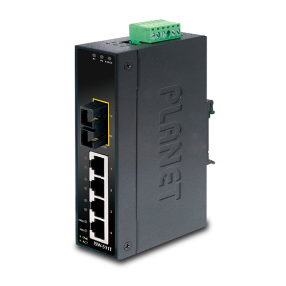
Basic knowledge of networking is assumed. Please read this chapter completely before continuing. 2.1 Product Description PLANET ISW-511 / ISW-621 series and ISW-511T / ISW-621T series are 4-Port 10/100Mbps + 1/2 100FX Fiber Port Industrial Fast Ethernet Switch with non-blocking wire-speed performance and new slim type with IP30 metal case for easy deployment in Heavy Industrial demanding environments. -
Page 15: Switch Front Panel
2.1.1 Switch Front Panel Figures 2-1, 2-2, 2-3 and 2-4 show their front panels. P2 FAULT P2 FAULT LNK/ACT LNK/ACT LNK/ACT 10/100 10/100 ISW-511 ISW-621 LNK/ACT LNK/ACT Figure 2-1 ISW-511 / ISW-511S15 Figure 2-2 ISW-621 / ISW-621S15 Front Panel Front Panel... - Page 16 P2 FAULT P2 FAULT P2 FAULT LNK/ LNK/ACT LNK/ LNK/ACT LNK/ACT 10/100 10/100 10/100 ISW-511T ISW-621TF ISW-621T LNK/ACT LNK/ACT LNK/ACT Figure 2-3 ISW-511T / Figure 2-4 ISW-621T / Figure 2-5 ISW-621TF ISW-511TS15 ISW-621TS15 Front Panel Front Panel Front Panel...
-
Page 17: Led Indicators
2.1.2 LED Indicators Color Function Green Lit: indicates power 1 has power. Green Lit: indicates power 2 has power. Lit: indicates either power 1 or power 2 has no FAULT Green power. Lit: indicates the Fiber port is Fiber Green successfully connecting to the network Optic at 100Mbps. -
Page 18: Wiring The Power Inputs
2.1.4 Wiring the Power Inputs The 6-contact terminal block connector on the top panel of Industrial Fast Ethernet Switch is used for two DC redundant powers input. Please follow the steps below to insert the power wire. 1. Insert positive / negative DC power wires into contacts 1 and 2 for POWER 1, or 5 and 6 for POWER 2. -
Page 19: Wiring The Fault Alarm Contact
The wire gauge for the terminal block should be in the range between 12 and 24 AWG. Note 2.1.5 Wiring the Fault Alarm Contact The fault alarm contacts are in the middle of the terminal block connector as the picture shows below. Inserting the wires, the Industrial Fast Ethernet Switch will detect the fault status of the power failure, or port link failure (available for managed model) and then forms an open circuit. -
Page 20: Mounting Installation
Manual uses IGS-801 (PLANET 8-Port Industrial Gigabit Switch) as the example. However, the steps for PLANET Industrial Note Switch and Industrial Media Converter are similar. 2.2.1 Install DIN-Rail Mounting The DIN-Rail is screwed on the Industrial Gigabit Ethernet Switch when out of factory. - Page 21 Step 2: Lightly insert the bottom of the switch into the track. Step 3: Check whether the DIN-rail is tightly on the track. Step 4: Please refer to the following procedures to remove the Industrial Fast Ethernet Switch from the track. Step 5: To remove the wall mount plate, reverse the steps above.
-
Page 22: Wall Mount Plate Mounting
2.2.2 Wall Mount Plate Mounting To install the Industrial Fast Ethernet Switch on the wall, please follow the instructions described below. Step 1: To remove the DIN-Rail from the Industrial Fast Ethernet Switch; loosen the screws to remove the DIN-rail. Step 2: Place the wall mount plate on the rear panel of the Industrial Fast Ethernet Switch. - Page 24 Weather Station Desert IP Camera IP Camera ISW-511TS15 ISW-511TS15 15km 15km IP Camera IP Camera Fiber Switch 15km Data Center 15km ISW-511TS15 IP Camera 15km ISW-511TS15 ISW-511TS15 ISW-511T Steel Factory Winter season of Country 100Base-FX Fiber-optic 100Base-TX UTP Weather Station Desert IP Camera IP Camera...
- Page 25 Weather Station Desert IP Camera IP Camera IP Camera 20km (Single mode) IP Camera ISW-621TF ISW-621TF 20km Fiber (Single mode) Switch 60km (Multi-mode) Data Center (Single mode) ISW-621TF IP Camera IP Camera 2km (Multi-mode) 2km (Multi-mode) ISW-621TF ISW-621TF ISW-621TF Steel Factory Winter season of Country 100Base-FX Fiber-optic 100Base-TX UTP...
- Page 26 Installation Steps Step 1: Unpack the Industrial Fast Ethernet Switch. Step 2: Check whether the DIN-rail is screwed on the Industrial Fast Ethernet Switch. (Please refer to DIN-rail mounting section for DIN-rail installation. If you want to wallmount the Industrial Fast Ethernet Switch, then please refer to the Wall- mount Plate Mounting section for wallmount plate installation.
-
Page 27: Switch Operation
4. Switch Operation 4.1 Address Table The Industrial Fast Ethernet Switch is implemented with an address table. This address table is composed of many entries. Each entry is used to store the address information of some node in the network, including MAC address, port no., etc. -
Page 28: Store-And-Forward
4.4 Store-and-Forward Store-and-Forward is one type of packet-forwarding techniques. Store-and-Forward Industrial Switch stores incoming frames in an internal buffer and checks any error from the frames before transmission. No error packets occurrence, it is the best choice when a network needs efficiency and stability. The Industrial Fast Ethernet Switch scans the destination address from the packet-header, searches the routing table provided for the incoming port and forwards the packet, only if required. -
Page 29: Troubleshooting
5. Troubleshooting This chapter contains information to help you solve issues. If the Industrial Fast Ethernet Switch is not functioning properly, make sure the Industrial Fast Ethernet Switch was set up according to instructions in this manual. The Link LED is not lit Solution: Check the cable connection of the Industrial Fast Ethernet Switch. -
Page 30: Appendix A: Networking Connection
APPENDIX A: Networking Connection A.1 Switch’s RJ45 Pin Assignments 10/100Mbps, 10/100BASE-TX RJ45 Connector pin assignment MDI-X Contact Media Dependent Media Dependent Interface Interface -Cross Tx + (transmit) Rx + (receive) Tx - (transmit) Rx - (receive) Rx + (receive) Tx + (transmit) 4, 5 Not used Rx - (receive) -
Page 31: Rj45 Cable Pin Assignments
A.2 RJ45 cable Pin Assignments The standard RJ45 receptacle/connector There are 8 wires on a standard UTP/STP cable and each wire is color- coded. The following shows the pin allocation and color of straight- through cable and crossover cable connection: Straight Cable SIDE 1 SIDE 2... - Page 32 ISW-621 / ISW-621S15 / ISW-621T / ISW-621TS15 / ISW-621TF * Produced by: Manufacturer‘s Name : Planet Technology Corp. Manufacturer‘s Address : 10F., No.96, Minquan Rd., Xindian Dist., New Taipei City 231, Taiwan (R.O.C.) is herewith confirmed to comply with the requirements set out in the Council Directive on the Approximation of the Laws of the Member States relating to Electromagnetic Compatibility Directive on (2004/108/EC).